
Related Manuals for Wohler AMP1-S8DA


Summary of Contents for Wohler AMP1-S8DA
- Page 2 Wohler Technologies, Inc. reserves the right to change or improve our products at any time and without notice. In no event will Wohler Technologies, Inc. be liable for direct, indirect, special, incidental, or consequential damages resulting from any defect in the hardware, software, or its documentation, even if advised of the possibility of such damages.
- Page 7 The preface lists the new features and functionality for this release.
- Page 8 AMP2-S8MDA AMP2-S8MDA-3G Moreover, we are replacing some similar products as well that may also include other changes. AMP1-S8DA (PN 8101-0030) AMP1-S8DA (PN 8101-0110) AMP2-S8DA (PN 8103-0020) AMP2-S8DA (PN 8102-0060) In this release, all terminations are no longer on the rear panel; they are now controlled by the software.
- Page 11 This chapter describes the front panel controls and the rear panel connectors in detail. It also describes how to use the front panel user interface for data display and system configuration. Configuration procedures are covered in detail in Chapter 3 on page...
- Page 12 Unpack the AMPx-S8 Series monitor and inspect for any apparent physical damage that may have occurred in transit. If the unit has been damaged, contact Wohler customer support for assistance. (Wohler’s contact information is on page ii of this document.) In addition to the monitor, the package should contain: •...
- Page 13 Protect the power cord from being walked on or pinched, particularly at plug’s source on the equipment and at the socket. Use only the attachments/accessories specified by the manufacturer. Unplug the equipment during lightning storms or when unused for long periods of time. Use of a cart is neither recommended nor approved by Wohler.
- Page 14 environment. This equipment generates, uses, and can radiate radio frequency energy and, if not installed and used in accordance with the instruction manual, may cause harmful interference to radio communications. Operation of this equipment in a residential area is likely to cause harmful interference in which case the user will be required to correct the interference at his own expense.
- Page 15 The ambient temperature inside the mounting enclosure should not exceed 40° Celsius (104° Fahrenheit). Adjacent devices can be rack mounted (or stacked) in proximity to the unit if this temperature is not exceeded. Otherwise, allow a 1RU (1.75”/44.45mm) space above and below the unit for air circulation.
- Page 16 Be careful to apply proper input termination settings and avoid mismatched cable types and other similar causes of undesired reflections in digital signal systems. If severe enough, such reflections can result in corruption of the digital data stream. As with any audio equipment, maximum immunity from electrical interference requires the use of shielded cable;...
- Page 17 The AMPx-S8 Series monitors are factory-configured so that all settings are non-volatile. When power to the unit is cycled (off/on), the unit will restore itself so that each setting such as channel selection(s), input type, and so on, are automatically restored to the unit’s previous factory setting.
- Page 19 This chapter describes how to install the AMPx-S8 Series monitor into a standard 19”-rack and how to connect the audio cables.
- Page 20 Refer to the images in Figure 2–1 Figure 2–2 on the next page. In addition, on the AMP1s, the top LED segment of each bar graph serves as the speaker assign LED for the respective channel. • Speakers: The AMP2s features two mid-range speakers (left and right) and one woofer speaker.
- Page 22 • Level Meter Brightness (Potentiometers, Left and Right): Use a small slot screwdriver to adjust the brightness of the bar graph meters using these two recessed trim pot controls. The left control adjusts the brightness of the left four LED bar graphs and the right control adjusts the brightness of the right four bar graphs.
- Page 23 then they will display as short dashes. Each dash (-) indicates a position for displaying the channel pairs available for monitoring from left to right: 1/2, 3/4, 5/6 and 7/8. The unit updates the whenever it detects a signal change. See Figure 2–3 and below for an example.
- Page 24 Like an “Escape” key: Attaches the right Selects the next Cancels and returns to speaker to the next higher-numbered the previous menu higher-numbered pair. option channel. Like an “Enter” key: Attaches the right Accepts changes, or speaker to the next Selects the next lower- drills deeper into the lower-numbered...
- Page 25 • Analog In (DB-25-F): This connector accepts balanced, low impedance, line level analog signals. See Figure 2–4 below for pin- out information. • Power: Attach a standard IEC-320 power cord between this connector and AC mains power. • AES/PCM In (1 through 4, BNC-F): These connectors accept unbalanced (75 ) PCM (AES/EBU) formatted signals.
- Page 27 • 3G/HD/SD-SDI In (1 and 2, BNC-F): These inputs accept SDI video signals for the 3G models. The DA model does not feature SDI capability. • Metered Analog (DB-25): This connector outputs the analog signal that is displayed on the front panel level meters. The pin-out information for this DB-25 is identical to that of the connector.
- Page 28 determine which audio pairs are de-embedded on these 75 , unbalanced, AES outputs. No other monitoring function affects these outputs. The pinout of this connector is the same as that for a standard VGA cable. VGA cables may be used to break out the HD-15 connectors into separate BNCs.
- Page 29 • Selected Downmix/Analog Out (Left and Right, XLR-M): These connectors are balanced analog outputs of the speaker assign (or downmix) source as selected for the left and right speaker channels. See the pin-out diagram in Figure 2–10 on page • AES Bal In/Loop Out (DB-25): This connector contains both inputs and looped outputs.
- Page 30 • RS-232 A (DB-9): This connector is used for downloading programming, setup, and diagnostic information into and out of the main board. • RS-232 B (DB-9): Not Used • RS-232 C (DB-9) (not available on the DA models): This connector is used for downloading programming, setup, and diagnostic information into and out of the 3G card.
- Page 31 OPT 2 (10-Position Rotary Switch): This recessed 10-position rotary • switch allows for standard operation and software upgrades. Refer Table 2–5 for the position values. 0 thru 7 Operational Mode (Default=1) 8 thru 9 Software Upgrade • SDI Option (10-Position Rotary Switch): This recessed 10-position rotary switch that is reserved for future use and should be left at the factory position of 1.
- Page 32 Custom Settings for Alternate Scales Not Used For software Upgrades Only Choosing position 2 (0 dBu = -20 dBFS) means an analog input level of 0 dBu will light up the LED segment associated with the digital -20 dBFS value on the bar graph meter and also transition from green to amber at that segment.
- Page 33 Continue on to Channel Selection and Mixing on page To monitor an AES signal, do one or both of the following: • Connect an unbalanced AES signal to the rear panel (BNC), and/or • Connect a balanced AES signal to the rear panel (DB-25).
- Page 34 Continue on to Channel Selection and Mixing immediately below. The level meters will operate automatically, displaying volume levels for each channel carrying an input signal. To produce audio through the internal speakers, press each of the buttons ( on page 20) until each channel is output through the speaker of your choice.
- Page 35 This chapter is the “how to” chapter. All topics listed below are sorted alphabetically for easy reference. For information about presets refer to Chapter Presets on page...
- Page 36 The Analog Output Preference determines how the connectors and the connector output the metered signals when either the DM1, DM2, or DM3 downmix options are selected. Refer to Rear Panel Connectors on page The default setting is , which outputs the speaker assign with individual channel scaling (gain settings) intact as determined by the selected downmix.
- Page 37 Press either the arrow followed by the button to change the setting, or press the button to leave it as is. Press the button again to return to normal operation. Press any of the eight speaker assign buttons to activate the mixing (summing) feature.
- Page 38 This mode allows you to select one and only one signal for each speaker independently of the other speaker and is most useful when you are monitoring mono sources. To select channels individually for each speaker: Press the buttons to enable single channel selection. Press the buttons to cycle through the channel selections for the left speaker.
- Page 39 This mode is most useful when multiple signals need to be mixed together and monitored at the same time. DM1-3 are designed for 5.1 surround sound signals, and assume a channel arrangement of (Channels 1-6 respectively): • Left Front, Right Front, •...
- Page 40 • DM2: You can use this downmix to create a two speaker assignments that can be decoded to multi-channel program by the use of an external surround decoder. Contribution of the surround speaker Assign is set by the surround level entry in the .
- Page 41 • DM3: This downmix is the same as DM1 except that the surround level is fixed at –3 dB. DM3 is equivalent to the Japanese ARIB Set 3 downmix formula. See Figure 3–9 below. • 4+4: In this downmix Channels 1 through 4 are summed to the left speaker and Channels 5 through 8 are summed to the right speaker.
- Page 42 Pressing the button allows you to step through three mute states and an unmuted state. When the system is in one of the mute states, all other information normally shown in the LCD such as the is disabled. In addition, all other buttons are disabled until you unmute the system.
- Page 43 With typical stereo program material, the moving block display is normal. If the signals to the speakers are completely independent, they will have a correlation result of 0, and the block will be stationary in the center of the screen. See Figure 3–10 below for an example.
- Page 44 Group 1 Group 2 Group 3 Group 4 Group 1 Group 2 Group 1 Group 3 Group 1 Group 4 Group 2 Group 3 Group 2 Group 4 Group 3 Group 4 Now press the button more slowly to toggle between selections.
- Page 45 Press either the buttons to select the delay in milliseconds from 10 to 170 for units equipped with a 919300 SDI De-embedder, or from 10 to 340 for units equipped with a 9193989 SDI De-embedder. Press the button to make your selection and return to the Press the button to return to normal operation.
- Page 46 You can configure the AMPx-S8 Series monitor to start up from a powered-off state, and automatically begin monitoring a particular input. Press the buttons. Press the button until the LCD screens as shown Figure 3–13 below. Press the button to display the list.
- Page 47 Each of the AES and bitstream inputs on the AMPx-S8 may be terminated or unterminated independently of each other. A given input should be terminated when the AMPx-S8 is the last receiving device in the signal path or is the only receiving device in the signal path.
- Page 48 Press the or the buttons until the desired input is shown on the screen. Press the key to change the termination setting for that input. Repeat Steps 4 and 5 until all the inputs have been set according to your needs. To exit the menu, press the arrow buttons until appears in the LCD, as shown in...
- Page 49 This chapter describes how to create, recall, modify, and erase presets. It also discusses using mode for fast system configuration.
- Page 50 The AMP1-E8 is an incredibly flexible tool for monitoring multiple audio streams. You can configure the entire system to function exactly the way you want it to for your specific application. You can store a complete system configuration into a preset. After saving one or more presets, you can quickly scroll through them with the press of a single button.
- Page 51 When this mode is enabled, you can no longer directly select the inputs by the input type (e.g., AES 1, SDI 2, analog, and so on). The inputs are accessed only indirectly through the presets in this mode. To access the inputs by input type, you must first disable mode.
- Page 52 Press If Preset 1 is currently empty, the system will prompt you to save and name the current unit configuration to Preset 1. Name the preset by using the arrow buttons to scroll through the available list of characters. Press to accept each character.
- Page 53 Name the preset by using the arrow buttons to scroll through the available list of characters. Press accept the character; repeat the process until all the characters have been entered. When all the characters have been entered, scroll until appears in the window, and press is located between the lowercase letters and before the numbers.
- Page 55 This chapter explains the options in the menu. Figure 5–1 on page provides a structural overview.
- Page 56 Normal Enter/Esc Setup: Startup ++ Choose Preset Num Norm al Operation Preset1: O n Site Last Used Enter Analog 0 through 9 Fn + Setup AES 1 AES 2 A Vld Det Setup M enu Enter Enter/Esc SDI 1 /Esc RCallPSet + Ena/Disa SDI 2...
- Page 57 Enable mode by pressing and holding the button and then pressing the button. This mode is used to change unit features. You can step through the menu selections and parameters using buttons. Press the button to save your selections. To cancel the option and exit the menu, press the button.
- Page 58 To exit , press the button. , and options will not be available if a preset has not been previously saved to the unit. See Saving a Preset on page 47 for how to save a preset of the current unit configuration. To change the , select then press the...
- Page 59 Press the buttons to scroll through the presets. In the example above (Figure 5–2), Preset 1 is called . If a particular preset is not assigned, it will be indicated as , as shown in Figure 5–3 below. Press the button with the desired preset displayed to recall that preset.
- Page 60 To cancel the procedure at any time during this process, press the button and the preset will not be saved and the unit will return to normal operation. Press either the buttons to choose any preset labelled Press the button to display a prompt for a new preset name as shown in Figure 5–5.
- Page 61 Naming will automatically end after you select eight characters, or when you press the button when appears on the display. See Figure 5–6 above. selection comes before the numerals, and follows the lower case alphabet. The character order is the order of ASCII characters. After naming the preset, the current state of the system is saved under that name and preset number, and the system returns to normal operation.
- Page 62 Pressing the button keeps the old name for the new preset and returns the unit to normal operation. This concludes the procedure for overwriting an existing preset with the same name. Pressing the button displays a prompt for a new preset name as shown in Figure 5–9 below.
- Page 63 For more information about presets Refer to Chapter Setup Menu on page To enable or disable mode: Press Use the arrow buttons until appears in the LCD window and press This selection will not appear if all the presets are empty.
- Page 64 Pressing the button will erase that preset. Pressing the button will not erase that preset. In either case, control returns to the menu to choose another preset to erase. Press the button to exit Setup Mode and return to This menu item is not available if this unit has no de-embedder card. This feature allows you to change the amount of delay added to the de- embedded audio signals from the SDI inputs.
- Page 65 entry within the determines the input used by the unit at power up. When set to , the unit will power up the same way that the unit was before power was interrupted. If instead you want to have the unit start up every time with the same input selected, repeatedly press the buttons until the desired input is shown in the LCD.
- Page 66 The unit will now mute an input pair if it detects the presence of a non- PCM stream (such as a Dolby or DTS bitstream) on that pair. The unit detects bitstreams with two methods: Preamble detection Not-Audio AES Channel status flag is asserted In terms of Method A, encoded bitstreams contain key data sequences that identify the type of encoding used.
- Page 67 For units with SDI de-embedder cards installed, there may or may not be a menu item available, entitled Phase Bts, which stands for phase bits. If this menu item is not available, then the presence or lack of proper phase bits is ignored and the product decodes audio properly regardless of whether other attached equipment is setting the bits correctly.
- Page 69 This chapter details the features of each of the monitors in the series and provides the technical specifications. It also outlines the distinctions between models.
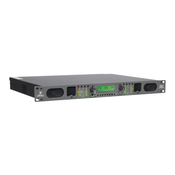
- Page 70 The AMPx-S8 Series audio monitors provide a complete, exceptionally high-quality 3G/HD/SD-SDI, PCM and analog stereo audio monitoring solution. A significant feature is the ability to monitor up to eight channels of a 3G-SDI, HD-SDI and/or SD-SDI bitstream, two sets of four AES/EBU signal pairs (balanced and unbalanced) or eight analog channels.
- Page 71 Power Consumption 72 W max AC Mains Input 100 to 240 VAC, 50 to 60 Hz Analog Input Impedance balanced, minimum AES Input Configuration balanced, 75 unbalanced Analog Input Overload +24 dBu balanced Analog Reference +8, +6, +4, or 0 dBu Digital Reference -20, -18, or -9 dBFS Meter Dynamics (AES Scale)
- Page 72 • AES (D-Sub 25, 4 BNC) Inputs • 3G/HD/SD-SDI (2 BNC) • Analog (D-Sub 25) • Metered Analog (DB-25) • 3G/HD/SD-SDI Re-Clocked (BNC) • AES Unbalanced Out from SDI (HD-15) • (Optional) Balanced AES Out from SDI Input Outputs (DB-25) •...
- Page 73 Control Panel Front with Summing Channel & Matrix Analog...
- Page 74 Control Panel Front with Summing Channel & Matrix Analog...
- Page 75 Control Panel Front with Summing Channel & Matrix Analog...
- Page 76 Control Panel Front with Summing Channel & Matrix Analog...
Need help?
Do you have a question about the AMP1-S8DA and is the answer not in the manual?
Questions and answers