Table of Contents
Advertisement
Quick Links
Advertisement
Table of Contents

Subscribe to Our Youtube Channel
Related Manuals for Parweld XTP 103


Summary of Contents for Parweld XTP 103
- Page 1 XTP 103 OPERATOR MANUAL ISSUE 3...
- Page 2 Thank you and congratulations on choosing Parweld. This Owner’s Manual is designed to help you get the most out of your Parweld products. Please take time to read the Safety precautions. They will help you protect yourself against potential hazards in the workplace. With proper maintenance this equipment should provide years of reliable service.
-
Page 3: Table Of Contents
Contents Page 1.0 Safety Precautions 2.0 Product description 3.0 Technical Specifications 4.0 Description of controls 5.0 Installation 5.1 Unpacking the Machine 5.2 Location 5.3 Input and grounding connection 5.4 Torch Installation 5.5 Work return lead connection 6.0 Operation 6.1 Consumable parts 6.2 switching on the machine 6.3 Setting the Air pressure 6.4 Getting ready to Cut... -
Page 4: Safety Precautions
Protect yourself and others from flying sparks and hot metal. contact with any metal object. Be alert that welding sparks and hot materials from welding can easily go through small cracks and openings to adjacent areas. Watch for fire, and keep a fire extinguisher nearby. Be aware that www.parweld.co.uk... -
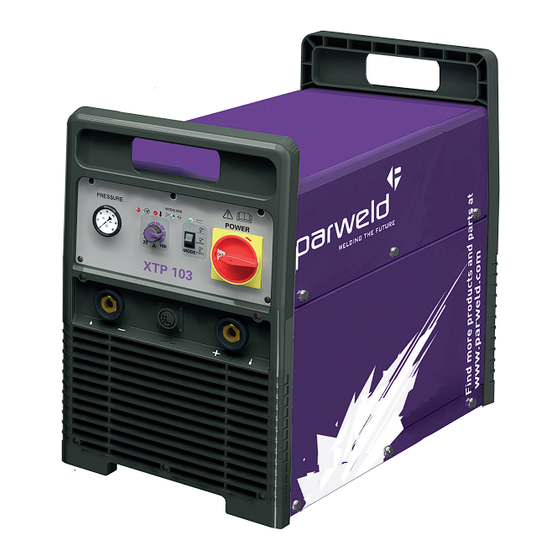
Page 5: Product Description
Turn face away from valve outlet when opening cylinder valve. Use the right equipment, correct procedures, and sufficient number of persons to lift and move cylinders. www.parweld.co.uk... -
Page 6: Description Of Controls
5) Fault light This indicates a fault or over temperature condition with the machine refer to the fault finding section for further information 6) AC input power on 7) Input pressure indicator 8) Output power control for adjustment of the power output of the machine between 20 and 100Amps. www.parweld.co.uk... -
Page 7: Torch Installation
The life of the electrode is dependant upon the cut amperage and the number of starting operations performed. The higher start frequency and cutting power will give the shortest electrode life. Check the electrode condition every 30 minutes of cutting. www.parweld.co.uk... -
Page 8: Cut Quality
If the cutting arc is interrupted, the cutting process must be restarted. To shut off the torch simply release the trigger switch. When the switch is released a 15 second post-flow will occur. The torch may be restarted by pressing the trigger at any time. www.parweld.co.uk... - Page 9 Cutting tip or electrode re-install the tip and illuminates not installed correctly electrode. Restart when trigger the power source pressed, and Have it checked by Short circuit in side the the air flow is a qualified engineer torch or cable intromittent www.parweld.co.uk...
-
Page 10: Accessories
Carriage PWPF155 Torch Head c/w FH563 Diffuser PC103 Contact Cutting Nozzle PWTP110 Handle with Trigger PC131 Contact Cutting Nozzle Long Life FH297 Insulator Washer PC101 Outside Nozzle PC102 Heavy Duty Nozzle PD101-14 Cutting Tip 1.4mm PD101-17 Cutting Tip 1.7mm www.parweld.co.uk... -
Page 11: Torch Spares
Parweld XT4000 Rating: 60A @ 80% Can be use for detail cutting on the XTP103 upto 60A in non HF mode the machine will detect if this torch is fitted. Technical Data Consumables Stock Code Description Voltage Class Standard Length... -
Page 12: Cnc Interface Setup
13 Yellow contact closure when arc 14 Yellow transfers . 120VAC/1A maximum at the machine interface relay or switching device Ground Ground Voltage divider Output When cutting arc signal 6(+) 7(-) 6 Red divided max 18V at 20:1 7 Black www.parweld.co.uk... - Page 13 (supplied by the customer). Ground Ground 13 (yellow & green) Voltage divider Output Divided arc signal of 20:1, 6 (+) 6 (orange) 21.1:1, 30:1, 40:1, 50:1 5 (-) 5 (black) (provides a maximum of 18 V). www.parweld.co.uk...
- Page 14 The factory presets the voltage divider to 20:1. To change the voltage divider to a different setting: 1. Turn OFF the power supply and disconnect the power cord. 2. Remove the power supply cover. 3. Locate the voltage divider DIP switches on the left side of the power supply top tray 20:1 30:1 www.parweld.co.uk...
- Page 15 40:1 50:1 www.parweld.co.uk...
- Page 16 3. Locate the voltage divider DIP switches on the PCB. Scale Selection 20:1 21.1:1 30:1 40:1 50:1 Switch Dial Number 20.1 21.1:1 30:1 40:1 50:1 1 2 3 4 1 2 3 4 1 2 3 4 1 2 3 4 1 2 3 4 www.parweld.co.uk...
- Page 17 www.parweld.co.uk...
-
Page 18: Ec Declaration Of Conformity
@ParweldLtd ParweldTV parweld_uk 10.0 EC Declaration of Conformity Hereby we declare that the machines as stated below Type: XTP 103 Conform to the EC Directives: Low Voltage Directive 2014/35/EEC EMC Directive 2014/35/EEC Harmonised European standard: EN/IEC 60974-1 This is to certify that the tested sample is in conformity with all provisions of the above detailed EU directives and product standards. -
Page 19: Weee Statement
WEE compliance outside the UK please contact your supplier/Importer Parweld is registered with a compliance scheme Official registration number is WEE/FD0255QV When your equipment reaches the end of its service life you should return it to Parweld where it will be reconditioned or processed for recycling. - Page 20 Parweld Limited Bewdley Business Park Long Bank Bewdley Worcestershire England DY12 2TZ tel. +44 1299 266800 fax. +44 1299 266900 www.parweld.co.uk info@parweld.co.uk...
Need help?
Do you have a question about the XTP 103 and is the answer not in the manual?
Questions and answers