Table of Contents
Advertisement
Quick Links
Advertisement
Table of Contents

Related Manuals for Barco FS40 MKII


Summary of Contents for Barco FS40 MKII
- Page 1 FS40 MKII / FL40 MKII User guide ENABLING BRIGHT OUTCOMES...
- Page 2 Product revision Software Revision: 2.1 Barco NV Beneluxpark 21, 8500 Kortrijk, Belgium www.barco.com/en/support www.barco.com Registered office: Barco NV President Kennedypark 35, 8500 Kortrijk, Belgium www.barco.com/en/support www.barco.com...
- Page 3 Barco. Changes Barco provides this manual 'as is' without warranty of any kind, either expressed or implied, including but not limited to the implied warranties or merchantability and fitness for a particular purpose. Barco may make improvements and/or changes to the product(s) and/or the program(s) described in this publication at any time without notice.
- Page 4 Patent protection Please refer to www.barco.com/about-barco/legal/patents. Disclaimer on GUI images used in this manual The GUI images in this manual are example illustrations and should be treated as such. While the name of the projector displayed in the illustrations may be different from the projector model you are currently using, the...
-
Page 5: Table Of Contents
3.8.6 Enable / Disable Remote Control........................30 3.8.7 Wired RC connection..............................31 Projector Address ...................................31 3.9.1 Controlling the projector ............................32 3.10 Connector panel ....................................32 4 Getting the projector started ...............................35 Projector source and control connections.........................36 R5913251 /07 FS40 MKII / FL40 MKII... - Page 6 Edit the RealColor presets.............................61 6.8.3 Output resolution 4K..............................62 6.8.4 Smear reduction ................................63 6.8.5 Brilliant color ..................................63 6.8.6 Displaying HDR content– Perceptual Quantizer (PQ) ................64 6.8.7 HDR Status..................................64 6.8.8 Night vision ..................................65 7 Installation menu....................................67 R5913251 /07 FS40 MKII / FL40 MKII...
- Page 7 AutoStereo (3D) Setup............................101 8 GUI – Profiles ......................................103 Profiles introduction ..................................104 Saving the current projector settings in a profile ......................105 Assigning a created projector profile to a preset......................106 R5913251 /07 FS40 MKII / FL40 MKII...
- Page 8 14 Calibration routines..................................159 14.1 Voltage calibration ..................................160 14.2 Color calibration.................................... 160 14.3 Advanced settings – Tilt sensor calibration........................162 15 User maintenance — Cleaning the projector ......................165 15.1 Projector lenses .................................... 166 R5913251 /07 FS40 MKII / FL40 MKII...
- Page 9 Latency ......................................188 DMD display device..................................188 Image display ....................................188 Image positioning..................................190 D Advanced blend ....................................191 Advanced blend, file creation..............................192 Example files ....................................193 User interface....................................195 Index ..........................................199 R5913251 /07 FS40 MKII / FL40 MKII...
- Page 10 R5913251 /07 FS40 MKII / FL40 MKII...
-
Page 11: Safety
Ensure that you understand and follow all safety guidelines, safety instructions and warnings mentioned in this chapter before installing the FL40 projector. Clarification of the term “FL40” used in this document When referring in this document to the term “FL40” means that the content is applicable for following Barco products: •... -
Page 12: General Considerations
HIGH BRIGHTNESS PROJECTORS) in performing a task, and of measures to minimize the potential risk to themselves or other persons. Only Barco authorized SERVICE PERSONNEL, knowledgeable of such risks, are allowed to perform service functions inside the product enclosure. The term USER and OPERATOR refers to any person other than SERVICE PERSONNEL. - Page 13 To prevent fire hazard • Barco projection products are designed and manufactured to meet the most stringent safety regulations. This projector radiates heat on its external surfaces and from ventilation ducts during normal operation, which is both normal and safe. Exposing flammable or combustible materials into close proximity of this projector could result in the spontaneous ignition of that material, resulting in a fire.
- Page 14 Never use water on an electrical fire. • Always have service performed on this projector by authorized Barco service personnel. Always insist on genuine Barco replacement parts. Never use non-Barco replacement parts as they may degrade the safety of this projector.
-
Page 15: Safety Symbols Fl40 / Fs40
CANADA: This Class A digital apparatus complies with Canadian ICES-003, / Cet appareil numerique de Ia classe est conforme à Ia norme NMB-003 du Canada. FL40 RG2 Label RG2 IEC EN 62471-5 R5913251 /07 FS40 MKII / FL40 MKII... -
Page 16: Location Of Labels
CANADA: This Class A digital apparatus complies with Canadian ICES-003, / Cet appareil numerique de Ia classe est conforme à Ia norme NMB-003 du Canada. Image 1–1 Location of RG2 and EMC label. R5913251 /07 FS40 MKII / FL40 MKII... -
Page 17: Important Notice
Important notice R5913251 /07 FS40 MKII / FL40 MKII... -
Page 18: Mechanical Noise During Startup
This mechanical noise is originating from the calibration process of the dimming disk during startup and is completely normal. It might also be noticeable when dimming the LED power below 50% output. R5913251 /07 FS40 MKII / FL40 MKII... -
Page 19: Getting To Know The Projector
Power on / Standby button backlight indications ................21 LCD Panel ...........................21 Local keypad..........................24 Shortcut buttons ...........................25 Basic remote control unit .......................26 Platinum remote control unit ......................27 Projector Address .........................31 3.10 Connector panel ...........................32 R5913251 /07 FS40 MKII / FL40 MKII... -
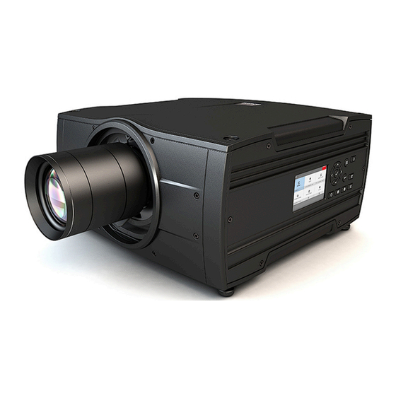
Page 20: Location Of The Main Exterior Components
Image 3–2 Main exterior components matrix Component Component Item Number Item Number IR Receiver top Projector feet (x4) IR Receiver front LCD Panel Lens Key Pad Lens release handle Back Panel / Connectors R5913251 /07 FS40 MKII / FL40 MKII... -
Page 21: Service And Maintenance
General The FL40 / FS 40 projectors does not have any user serviceable parts. All service tasks must only be carried out by the manufacturer, or a Barco authorized service personnel or Barco technicians. 3.3 Power on / Standby button backlight... -
Page 22: Lcd Touch Panel
Notifications: The error and/or warning messages that are currently active. If no messages are active, this list will be empty. • Preview: A preview pane of the projected image. If no image is being projected, a test image is displayed instead. Image 3–3 Dashboard page R5913251 /07 FS40 MKII / FL40 MKII... - Page 23 This function shows the output of the currently active source on the LCD panel. The source content should be a picture without warp and blend applied. The picture will be limited by the LCD resolution, 800x480pixels. R5913251 /07 FS40 MKII / FL40 MKII...
-
Page 24: Osd Menu Mode
The Standby key is equipped with white, blue and red backlight depending on the status of the projector. See table in “Power on / Standby button backlight indications”, page 21 for info regarding this. Image 3–7 R5913251 /07 FS40 MKII / FL40 MKII... -
Page 25: Shortcut Buttons
When the test pattern or input shortcut button is pressed, a pop up menu will show up on the LCD screen. Make a selection by the arrow keys, and confirm. Image 3–8 Test pattern pop up menu R5913251 /07 FS40 MKII / FL40 MKII... -
Page 26: Basic Remote Control Unit
About the basic remote In order to make sure you can control your projector remotely, Barco has provided a basic remote control unit in case the Pulse RCU is not available to you. While this remote control has a more limited amount of available features, it will be able to help you out with basic controls. -
Page 27: Platinum Remote Control Unit
(2). Image 3–11 Insert the two AA size batteries, making sure the polarities match the + and - marks inside the battery compartment. Tip: Use alkaline batteries for optimum range and lifetime. R5913251 /07 FS40 MKII / FL40 MKII... -
Page 28: Remote Control, Protocol Setup
The NEC protocol have to be used for Barco projectors based on the Pulse platform: Loki, Balder, F40. F70, F80, F90, HDX 4K, UDX, UDM and more.. • The RC5 protocol have to be use all other Barco projectors: HDX W, HDF W, HDQ 2K, ... (legacy products) How to set Remove the battery cover. -
Page 29: Functionality Overview
Image 3–14 Remark with RC5 protocol Not all buttons of the Pulse RCU are one-to-one compatible with the legacy Barco RCU. Button pairs SHUTTER open/close and POWER on/off emit the same code (per pair) when in RC5 mode, because the legacy RCU’s only had 1 button for Shutter and 1 button for Standby. -
Page 30: Pulse Rcu, Function Of The On/Off Button
After powering up, the colors will always revert back to full RGB. 3.8.6 Enable / Disable Remote Control About This function is for disabling the IR sensors for the remote control. Either front or rear, or both. Select the menu path Settings/Communication/IR control R5913251 /07 FS40 MKII / FL40 MKII... -
Page 31: Wired Rc Connection
It is not possible to program the remote control in wired mode. (Directly connected, no sense in programming). 3.9 Projector Address Projector address Address installed in the projector to be individually controlled. Broadcast address Projector will always execute the command coming from a RCU programmed with that broadcast address. R5913251 /07 FS40 MKII / FL40 MKII... -
Page 32: Controlling The Projector
NOTE Disconnect the projector power cable before connecting or removing the trigger cable Jack connector for wired For Projector Control remote USB 2.0 type A, 4 pin For Software upgrade Standard RJ45 connector For Projector Control R5913251 /07 FS40 MKII / FL40 MKII... - Page 33 HDCP compliant for sources up 165 Mhz HDMI Standard HDMI 2.0 For Projector Input HDBaseT Standard RJ45 8P8C For Projector Input Connector R5913251 /07 FS40 MKII / FL40 MKII...
- Page 34 Getting to know the projector. R5913251 /07 FS40 MKII / FL40 MKII...
-
Page 35: Getting The Projector Started
Getting the projector started Projector source and control connections ..................36 Power up the projector ........................39 Power down the projector......................39 Power mode transitions.........................40 Power modes ..........................41 Customize projector settings ......................42 User interface..........................42 R5913251 /07 FS40 MKII / FL40 MKII... -
Page 36: Projector Source And Control Connections
Standard Display port Signal characteristics DP 1.2 Functionality Mandatory Max. cable length 2 m (24 AWG) - RBR; 2 m (24 AWG) – HBR1, HBR2 Supported Link Rate RBR, HBR1, HBR2 Scan format Progressive R5913251 /07 FS40 MKII / FL40 MKII... -
Page 37: Specifications Hdmi 2.0
HDBaseT 1.0 Specification, June 2010 Connector Standard RJ-45, 8P8C Signal characteristics HDBaseT Max. cable length (1080p/48b/60Hz) 100 m (Cat5e/6), Pixel Clock <=225HHz, Video Datarate <=5.3Gbps 70 m (Cat5e/6), Pixel Clock >225HHz, Video Datarate >5.3Gbps R5913251 /07 FS40 MKII / FL40 MKII... -
Page 38: Control Interfaces
RS-232 connector 1 female DB9 connector (RS232-in) for projector control and debug 4.1.3.2 LAN/Ethernet Specifications Parameter Value Ethernet connector 1 RJ45 Connector for projector control (not content) Protocols DHCP, TCP/IP, UDP/P Speed 10/100 Mbit/1000Mbit R5913251 /07 FS40 MKII / FL40 MKII... -
Page 39: Power Up The Projector
Wait 2 minutes before disconnecting the power cord. (If disconnecting is required). WARNING: There is a risk of reducing the expected lifetime of the projectors DMD device if the power cord is removed too early, due to the device’s shutdown sequence. R5913251 /07 FS40 MKII / FL40 MKII... -
Page 40: Power Mode Transitions
Press the Power On/Off button on the projector, or the Power On button on the remote control. The projector will power ON. The Power On/Off button will BLINK BLUE during the transition from READY to ON. Once the projector is on, the Power On/Off button will be lit BLUE. R5913251 /07 FS40 MKII / FL40 MKII... -
Page 41: Going From On To Ready
Projector is booted up and the light source is on Ready Projector is booted up but the light source is off ECO Standby Light source is switched off and projector electronics are powered down R5913251 /07 FS40 MKII / FL40 MKII... -
Page 42: Customize Projector Settings
Service Code in the Service Menu or contact your support representative for more information. Define values Menu settings are displayed using checkboxes, barscale sliders, and selection boxes, depending on the type of menu. R5913251 /07 FS40 MKII / FL40 MKII... - Page 43 Changes to values are implemented dynamically. Menu memory The OSD menu remembers the last selected sub–item as long as the projector is running. The menu memory is reset when restarting the projector from standby. R5913251 /07 FS40 MKII / FL40 MKII...
- Page 44 Getting the projector started R5913251 /07 FS40 MKII / FL40 MKII...
-
Page 45: Source Menu
By navigate through the Source menu, it will be visible also on the OSD. By using the shortcut key, the menu occurs only on the LCD display. Image 5–1 R5913251 /07 FS40 MKII / FL40 MKII... -
Page 46: Connector Selection
When entering the menu for each input connector, you can change the following: • Color Space • Signal Range • EDID How to configure a connector Press Menu to activate the menus and select Source. R5913251 /07 FS40 MKII / FL40 MKII... - Page 47 The Source menu is displayed with the actual available sources filled out. Image 5–4 Source menu Scroll down to the bottom of the list of available sources and select Connector Settings. Image 5–5 The available input connectors are displayed. Select the desired connector. R5913251 /07 FS40 MKII / FL40 MKII...
-
Page 48: Using Dual Inputs
To enable this mode, select the source that fits in the Menu/Source Dual input modes There are four ways to connect dual input. • Dual Displayport Columns • Dual Displayport Sequential • Dual DVI Columns • Dual DVI Sequential R5913251 /07 FS40 MKII / FL40 MKII... -
Page 49: No Source Image
Press Menu to activate the menus and select Source. Image 5–10 Main menu, Source Press OK. The Select Source menu is displayed with the actual available sources filled out. Scroll down the list of available sources and press No source image. R5913251 /07 FS40 MKII / FL40 MKII... - Page 50 When custom background images have been uploaded using an external tool, they will be listed after the predefined images. Image 5–13 Example of the No source image menu with two custom background images. R5913251 /07 FS40 MKII / FL40 MKII...
-
Page 51: Image Menu
The operation of the menus can be done with both the remote control or the arrows on the keypad. It is also possible to switch between the different adjustments by using the up and down arrows, instead of exit one menu and then enter the next one. Image 6–1 R5913251 /07 FS40 MKII / FL40 MKII... - Page 52 When pressing enter on the value slider, this icon will show up on the OSD (depending which setting that is enabled, contrast showed here). When in this mode, use the up and down arrow keys to navigate between the different settings. Image 6–3 OSD menu R5913251 /07 FS40 MKII / FL40 MKII...
-
Page 53: Contrast
The brightness function is used to adjust the black level in the input picture. It adds or subtracts an offset, or bias in to the red, green and blue signals. Available range: –1.00 to 1.00 Default value: 0.00 Image 6–5 Brightness OSD menu R5913251 /07 FS40 MKII / FL40 MKII... -
Page 54: Saturation
In a natural picture, high sharpness can be perceived as noise, as all details in the picture will be amplified. Available range —2 to 8. Default value: 0 Image 6–7 Sharpness OSD menu R5913251 /07 FS40 MKII / FL40 MKII... -
Page 55: Gamma Adjustment
Use the arrow keys to select the most suitable gamma type. Select the gamma slider and tune the gamma value. Note: The Gamma slider in the Gamma menu will be disabled when DICOM, SIM or SRGB values is selected. R5913251 /07 FS40 MKII / FL40 MKII... -
Page 56: Gamma Types
270, select DICOM 250 from the drop down menu). Higher numeric value represent a brighter environment. Note: The Gamma slider in the Gamma menu will be disabled when DICOM, SIM or SRGB values is selected. R5913251 /07 FS40 MKII / FL40 MKII... -
Page 57: Digital Zoom Shift
See the illustrations below. The red lines in the figures represent the DMD outline. Enter the menu showed above and toggle the Digital zoom switch. Select the slider according to the instructions in the menu and move it to the desired zoom level. R5913251 /07 FS40 MKII / FL40 MKII... -
Page 58: Digital Shift
The numbers on the right side of the menu represent the movement (shift) of the picture in pixels referred to the “no shift” position. Positive numbers are shift right/down, and negative numbers are shift left/up. This function can also be used in combination with the Digital zoom function. R5913251 /07 FS40 MKII / FL40 MKII... -
Page 59: Advanced Image Adjustments
The selection of the presets will vary, depending on the projector type, and the color wheel installed. How to choose one of the P7 presets In the main menu, select Image → Advanced → P7 Realcolor. R5913251 /07 FS40 MKII / FL40 MKII... - Page 60 Note: When choosing one of the presets, All other options in the P7 menu are disabled. How to set custom P7 values In the main menu, select Image → Advanced → P7 Realcolor. Image 6–22 The P7 menu is displayed. R5913251 /07 FS40 MKII / FL40 MKII...
-
Page 61: Edit The Realcolor Presets
The values are stored for the preset, until the “Reset” button is enabled, or when a factory reset is performed. There is also a possibility to store the values in the custom presets.. Press the “Copy preset to custom” button to save. R5913251 /07 FS40 MKII / FL40 MKII... -
Page 62: Output Resolution 4K
With this function, the projector output resolution can be changed between 4K UHD resolution and WQXGA resolution. Refer to the chapter “Projector source and control connections” regarding use of input sources in 4K mode. R5913251 /07 FS40 MKII / FL40 MKII... -
Page 63: Smear Reduction
Optimizes the color rendering, by adjusting the light intensity. This has the effect of changing the color intensity, and by that also the perceived light intensity. Enter the menu, and select the option that give the best result R5913251 /07 FS40 MKII / FL40 MKII... -
Page 64: Displaying Hdr Content- Perceptual Quantizer (Pq)
When an active source is HDR, an icon is visible in the status menu. The HDR icon will also be visible in the “Source signal popup” icon in the lower right corner on the screen. R5913251 /07 FS40 MKII / FL40 MKII... -
Page 65: Night Vision
How to swap channels Select the Menu/ Image / Advanced / Night Vision. menu Toggle the Swap channel function on / off by pressing the OK button on the remote control or the keypad. Image 6–31 R5913251 /07 FS40 MKII / FL40 MKII... - Page 66 Image menu R5913251 /07 FS40 MKII / FL40 MKII...
-
Page 67: Installation Menu
Installation menu Position ............................68 Lens ............................70 Scaling modes..........................73 Warping ............................75 Blending ............................86 CLO feature ..........................93 IR / Night vision functionality......................97 Illumination ..........................99 3D setup / IG pixel shift .........................99 Menu overview Image 7–1 R5913251 /07 FS40 MKII / FL40 MKII... -
Page 68: Position
How to set the correct orientation In the main menu, select Installation → Position → Orientation. Image 7–3 Installation menu, orientation The Orientation menu is displayed. Image 7–4 Example of the orientation menu R5913251 /07 FS40 MKII / FL40 MKII... -
Page 69: Projector Tilt Indication
If you notice the tilt sensor isn’t working correctly (e.g. when compared to a level), you can calibrate the sensor in the settings menu. For more info, see “Advanced settings – Tilt sensor calibration”, page 162. R5913251 /07 FS40 MKII / FL40 MKII... -
Page 70: Lens
The projector allows for horizontal and vertical shift in both directions. Always place the projector perpendicular to the screen, and use the lens shift to align the picture. Use the Remote control or the keypad on the Projector to adjust the lens shift mechanism. R5913251 /07 FS40 MKII / FL40 MKII... -
Page 71: Shift To Center
Due to restrictions in light output for the EN 68 lens, the mid position for this lens will not be the mechanical mid position, but the mid position of the area where max light output is allowed. R5913251 /07 FS40 MKII / FL40 MKII... -
Page 72: Iris
Use the arrow keys to adjust Iris until preferred rendering is obtained. The numeric value in the menu indicates the degree of opening of the iris. Value = 0, full opening. (No iris activated). Increased numeric value indicates decreasing in the iris opening. (Iris activated). R5913251 /07 FS40 MKII / FL40 MKII... -
Page 73: Scaling Modes
Input signal (Source): 4 : 3 DMD Capacity: 1,6 : 1 (2560 x 1600 pixels) Screen: 2,35 : 1 (Cinemascope) Image 7–11 This mode is an exact rendering of the source signal, pixel by pixel R5913251 /07 FS40 MKII / FL40 MKII... - Page 74 / distorted compared with the source signal. Input signal (Source): 4 : 3 DMD Capacity: 1,6 : 1 (2560 x 1600pixels) Screen: 2,35 : 1 (Cinemascope) Image 7–14 How to enter. Enter the Menu/Installation/Scaling menu. R5913251 /07 FS40 MKII / FL40 MKII...
-
Page 75: Warping
The image will then typically occur as shown inImage 7–16. While an image can be transformed in various ways, pure warping doesn’t affect the colors. R5913251 /07 FS40 MKII / FL40 MKII... -
Page 76: Warping - On/Off
By toggling between on and off the warping functionality can be enabled or disabled. How to toggle In the main menu, select Installation → Warp. Image 7–17 Installation menu, warp The Warp menu is displayed. R5913251 /07 FS40 MKII / FL40 MKII... -
Page 77: Warping - Screen Size
Image 7–21 Warp outline example How to adjust the image? In the main menu, select Installation/Warp/Screensize. R5913251 /07 FS40 MKII / FL40 MKII... -
Page 78: Warp - 4 Corners Adjustment
To have a successful Warp correction, the size of the screen must be entered. See “Warping – Screen size”, page 77 Some examples of pictures when the projector axis is not perpendicular to the screen.: R5913251 /07 FS40 MKII / FL40 MKII... - Page 79 If the picture still has a trapezoid shape, warp is not enabled. Select the Installation / Warp menu, and press enter. The slider moves to the right, and the warp status changes to “On”. Image 7–26 R5913251 /07 FS40 MKII / FL40 MKII...
-
Page 80: Warping - Bow
When the bow menu is selected, a grid will occur in the screen picture in order to visualize the adjustments performed. To enable Bow correction, make sure the Bow slider is set to On. The slider is enabled when set to the right and when it is highlighted blue. R5913251 /07 FS40 MKII / FL40 MKII... - Page 81 When corrected with the values in the image above, the picture will occur as shown below. Repeat this step for all sides of the picture that has to be corrected. Image 7–32 Symmetric bow corection R5913251 /07 FS40 MKII / FL40 MKII...
- Page 82 When corrected with values in the illustrations above, the picture will occur as shown below. Observe that the upper side of the picture now has an asymmetric correction. Image 7–35 Asymmetric bow correction R5913251 /07 FS40 MKII / FL40 MKII...
-
Page 83: Warping - Warp Files
How to activate an uploaded Warp grid? In the main menu, select Installation → Warp. Image 7–37 Installation menu, Warp In the Warp menu, select Warp files. R5913251 /07 FS40 MKII / FL40 MKII... -
Page 84: Warping - Latency Control In A Multi Projector Setup
The total time from the first pixel is coming in on an input source, until the first light representing that pixel is visible on the screen. This includes the transport delay. The value is normally given in milliseconds. R5913251 /07 FS40 MKII / FL40 MKII... - Page 85 For each projector in the setup, select Installation → Warp in the main menu. Image 7–42 Installation menu, Warp In the Warp menu, select Transport Delay. Image 7–43 Warp menu, Transport delay The Transport delay menu is displayed. R5913251 /07 FS40 MKII / FL40 MKII...
-
Page 86: Blending
The offset adjustments are used to cut the image on each side. Normally used to hide parts of the picture that shall not be shown on the screen. An example can be: If the source is a pc, you may want to hide the menu bar at the bottom of the screen. R5913251 /07 FS40 MKII / FL40 MKII... -
Page 87: Set Up The System
OSD. (The number entered represent the blend width expressed in number of pixels). Use the enter key to move the cursor to the next position that has to be masked. R5913251 /07 FS40 MKII / FL40 MKII... -
Page 88: Basic Blend Setup Procedure
Repeat step 4 and 5 to adjust the rest of the blending zones. Exit the menu by using the exit button on the remote control. For horizontal blending, use the left/right arrow keys to adjust. For vertical blending, use the up/down arrow keys to adjust. R5913251 /07 FS40 MKII / FL40 MKII... -
Page 89: Black Level Setup Procedure
Select the menu Installation/Blend and mask/Black level. Enable the ”Black level” and “Show lines” buttons. A line that indicates the blend zones will be visible on the screen when “Show lines” is enabled. R5913251 /07 FS40 MKII / FL40 MKII... -
Page 90: Color Level Adjustment Procedure
So if the projected image of the projectors overlap, there will be 3 R5913251 /07 FS40 MKII / FL40 MKII... -
Page 91: Black Level Files
For more information on uploading/downloading Black Level files using the Prospector, refer to the Prospector user manual. For more information on uploading/downloading Black Level files using curl or other tools that supports HTTP upload, refer to the Pulse API Reference Guide. R5913251 /07 FS40 MKII / FL40 MKII... -
Page 92: Blend Files
For more information on uploading/downloading Blend files using curl or other tools that supports HTTP upload, refer to the Pulse API Reference Guide. How to activate an uploaded Blend configuration file? In the main menu, select Installation / Blend and mask / Blend files R5913251 /07 FS40 MKII / FL40 MKII... -
Page 93: Advanced Blend
7.6.1 Introduction Introduction The CLO (Constant Light Output) is a Barco Pulse software feature for maintaining a stable light output from the projector over time, by automatically adjusting the light source. The CLO feature utilizes a light sensor placed internally in the projectors light path. -
Page 94: Using The Clo Features
Explanation: The light source power is at its maximum and can no longer maintain the desired light output • L8000d Illumination cli light measuring failed Explanation: The CLO failed while trying to measure the light on the light sensor, either when enabling the CLO or during CLO operation R5913251 /07 FS40 MKII / FL40 MKII... -
Page 95: Example For Using The Clo Feature For Maintaining Brightness Over Time
The same prerequisites apply for this feature regarding the degradation of the light source and the initial set- point chosen for the light source power. The CLO scale can be set and / or monitored using the property: • illumination.clo.scale R5913251 /07 FS40 MKII / FL40 MKII... -
Page 96: Example: Clo Scale With One Projector
From a user perspective no interaction has been made with the projector, so a change to the hasstabilized signal in this case would not make sense. The functionality presented in a Given-When-Then format. R5913251 /07 FS40 MKII / FL40 MKII... -
Page 97: Ewma
7.6.7 Setpoint Setpoint This feature enables the user to set the desired value directly. As no max value is given Barco recommends using the CLO scale if different output power settings are needed when using the CLO. The setpoint can be set and/or monitored using the property: •... - Page 98 LED’s, Vizsim Bright must be set manually.“Brilliant color”, page 63 If not then set to Vizsim Bright, the picture will be distorted. Disable this functions in IR mode The Vizsim Bright mode will not cause this distortion. R5913251 /07 FS40 MKII / FL40 MKII...
-
Page 99: Illumination
Enter the menu, and use the sliders to adjust. Image 7–63 7.9 3D setup / IG pixel shift About All sub-menus, except from the IG Pixel shift, are described in other topics in this manual, where they more naturally belong. R5913251 /07 FS40 MKII / FL40 MKII... -
Page 100: Ig Pixel Shift
Select by pressing enter. Status menu When IG pixelshift is enabled, it will be visible in the Status Menu. (Scroll down a bit to see it), and also in the LCD Information display. R5913251 /07 FS40 MKII / FL40 MKII... -
Page 101: Ig Pixelshift Night Vision
DVI1/DP1 has a lower latency than the DVI2/DP2. Image 7–66 Image 7–67 7.9.3 AutoStereo (3D) Setup Enabling 3D mode See chapter “3D”, page 135 for 3D mode setup R5913251 /07 FS40 MKII / FL40 MKII... - Page 102 Installation menu R5913251 /07 FS40 MKII / FL40 MKII...
-
Page 103: Gui - Profiles
GUI – Profiles Profiles introduction ........................104 Saving the current projector settings in a profile ................105 Assigning a created projector profile to a preset ................106 Deleting a projector profile......................108 R5913251 /07 FS40 MKII / FL40 MKII... -
Page 104: Profiles Introduction
Swap eyes on / off • Swap frame pair on / off • Dark time and sync delay values Realcolor • Brilliant Color mode (if available) • P7 desired values • P7 measured values R5913251 /07 FS40 MKII / FL40 MKII... -
Page 105: Saving The Current Projector Settings In A Profile
In the main menu, select Profiles → Edit. Image 8–2 Profiles menu, edit The Profile edit menu is displayed. only valid if recalled with same lens Only if external cooler is installed Only for applicable models R5913251 /07 FS40 MKII / FL40 MKII... -
Page 106: Assigning A Created Projector Profile To A Preset
8.3 Assigning a created projector profile to a preset This procedure assumes you have created at least one projector profile. . How to assign a projector profile to a preset In the main menu, select Profiles → Edit. R5913251 /07 FS40 MKII / FL40 MKII... - Page 107 Image 8–7 Example of a projector profile with available preset slots Use the arrow keys to select a preset slot and confirm with the OK key. The selected preset slot is now shown next to the profile name. R5913251 /07 FS40 MKII / FL40 MKII...
-
Page 108: Deleting A Projector Profile
In the main menu, select Profiles → Edit. Image 8–9 Profiles menu, edit The edit menu is displayed. Image 8–10 Profile edit menu Select the undesired projector profile and confirm to expand it. R5913251 /07 FS40 MKII / FL40 MKII... - Page 109 GUI – Profiles Image 8–11 Example of a projector profile with available preset slots Use the arrow keys to select Delete and confirm. confirm the delete action. R5913251 /07 FS40 MKII / FL40 MKII...
- Page 110 GUI – Profiles R5913251 /07 FS40 MKII / FL40 MKII...
-
Page 111: System Settings Menu
Date and time..........................119 Power saving settings ......................... 121 Lens features ..........................124 Maintenance ..........................125 Lens calibration .......................... 125 Reset............................126 Controlling the backlight of the LCD Display.................. 128 Menu overview Image 9–1 R5913251 /07 FS40 MKII / FL40 MKII... -
Page 112: Communication
'0'. Any command coming from an RCU programmed with that common address will be executed. How to the broadcast address In the main menu, select Settings → Communication → Remote control. R5913251 /07 FS40 MKII / FL40 MKII... -
Page 113: Projector Address
Next to an individual projector address, each projector has also a broadcast address for group control. How to change In the main menu, select Settings → Communication → IR control. Image 9–5 Communication menu, Remote Control The Remote control menu is displayed. R5913251 /07 FS40 MKII / FL40 MKII... -
Page 114: Ir Sensors
You will only be able to use the remote control while its connected with the wired connector. How to disable In the main menu, select Settings → Communication → Remote control. Image 9–7 Communication menu, Remote Control The IR control menu is displayed. R5913251 /07 FS40 MKII / FL40 MKII... -
Page 115: Host Name - Custom Projector Name Setup
You can change this name to make it easier to spot in a network with multiple devices or projectors How to set a different Host name In the main menu, select Settings → Communication → Host name. Image 9–9 Communication menu, Host name The Host name menu is displayed. R5913251 /07 FS40 MKII / FL40 MKII... -
Page 116: Trigger
The trigger outputs can be individually set to active low or active high by entering the menu Settings / Communication / Triggers Image 9–11 F40 series trigger menu The time of trigger output is defined via an API code. Contact Barco support for detailed info. 9.2 User interface 9.2.1 Language Setting the menu language The menu language can be changed to a suitable language. -
Page 117: Themes
Enter the menu and select the preferred units by the arrow keys on the remote control. Temperature units: Celsius (C) and Fahrenheit (F). Distance units: Meter (M), Centimeters (C), Feet (FT) and Inches (IN) R5913251 /07 FS40 MKII / FL40 MKII... -
Page 118: Backlight / Stealth Mode
Stealth mode On: Stealth mode is enabled. When rebooting or upgrading SW the Stealth mode will be off until the projector reaches Ready. This allows the user to get feedback on e.g. the progress of the SW update R5913251 /07 FS40 MKII / FL40 MKII... -
Page 119: Date And Time
Slide the Day, Month and Year slider up or down until the desired date is obtained. Alternatively, use the up, down and OK buttons on the RCU or control panel until the desired date is obtained. R5913251 /07 FS40 MKII / FL40 MKII... -
Page 120: Date And Time Setup - Automatically
In the main menu, select Settings → Date and time. Image 9–18 The Date and time menu is displayed. Enable the Automatic slider. Image 9–19 Gray slider: automatic is off Blue slider: automatic is on Select Server and click OK. R5913251 /07 FS40 MKII / FL40 MKII... -
Page 121: Power Saving Settings
9.4 Power saving settings About the power saving features In the aspect of continuous improvement, Barco has added several power saving features to the projector, which will extend the lifetime of your projector and light source in particular. From Pulse software 2.3.x onward, the following power saving features are available:... - Page 122 Image 9–22 Settings menu, Power To enable or disable Auto dimming, proceed as follows: In the Power menu, click Auto dim. Image 9–23 Power menu, Auto dimming The Auto dimming menu is displayed. R5913251 /07 FS40 MKII / FL40 MKII...
- Page 123 When enabled, select the timeout period after which the light source will be turned off. To enable or disable the Auto standby feature, proceed as follows: In the Power menu, click Auto standby. R5913251 /07 FS40 MKII / FL40 MKII...
-
Page 124: Lens Features
Enter the menu shown below, and disable the desired functions by toggling the desired buttons. The menu below shows all lens options in enabled position. Image 9–29 R5913251 /07 FS40 MKII / FL40 MKII... -
Page 125: Maintenance
This function will calibrate the position of the iris and the horizontal and vertical lens shift. The purpose is to have an accurate feedback to the system Calibration Enter the menu Settings / Maintenance / Lens calibration. Select the feature that shall be calibrated, and press enter on the remote control R5913251 /07 FS40 MKII / FL40 MKII... -
Page 126: Reset
Disabled, no files selected ImageBlend Blend/Mask size disabled, all value to zero Black Level Black Level Files Disabled, no files selected Blend Files ImageRealColor P7 Realcolor all set to native ImageStereo Sync delay 0 µs R5913251 /07 FS40 MKII / FL40 MKII... - Page 127 Navigate to the checkbox next to the settings that need to be reset and press OK. Multiple selections are possible. Select RESET and press OK to reset all selected settings. Domains with * will also delete any uploaded files for that domain. R5913251 /07 FS40 MKII / FL40 MKII...
-
Page 128: Controlling The Backlight Of The Lcd Display
Image 9–34 Settings menu, backlight The Backlight menu will be displayed. Image 9–35 Example of the backlight menu Choose the desired setting for the backlights. Select one of the predetermined options, or a custom value. R5913251 /07 FS40 MKII / FL40 MKII... -
Page 129: Scheduler
Scheduler 10.1 About scheduler ......................... 130 10.2 Open the scheduler ........................130 10.3 Adding new command......................... 130 10.4 Edit or delete ..........................132 10.5 Clear the scheduler........................133 R5913251 /07 FS40 MKII / FL40 MKII... -
Page 130: About Scheduler
Tip: Make sure the Enabled slider is set to the right and lit blue. If not, the Scheduler will not be active. 10.3 Adding new command How to add a new command In the Scheduler menu, select Add Command. The Add Command page is displayed. R5913251 /07 FS40 MKII / FL40 MKII... - Page 131 “GUI – Profiles”, page 103 If Profile is selected, the currently available projector Profiles will be listed in the menu. Image 10–5 Example of the Add Command window with the available profiles listed R5913251 /07 FS40 MKII / FL40 MKII...
-
Page 132: Edit Or Delete
Image 10–7 Example of the Scheduler menu, with Power On being added. 10.4 Edit or delete How to edit or delete a command In the Scheduler menu, select and confirm an existing command. The Edit Command window will be prompted. R5913251 /07 FS40 MKII / FL40 MKII... -
Page 133: Clear The Scheduler
Confirm the action by clicking Confirm. Note: If you clicked the Clear All button by accident, click Cancel instead to cancel and return to the Scheduler menu. All actions in the Scheduler will be deleted. R5913251 /07 FS40 MKII / FL40 MKII... - Page 134 Scheduler R5913251 /07 FS40 MKII / FL40 MKII...
-
Page 135: 135
Use two channel input (two cables), one for each eye. Update frequency limited to 60 Hz for each channel. Dual Sequential input source (DVI or Displayport) must be used. No external sync signal required. R5913251 /07 FS40 MKII / FL40 MKII... -
Page 136: Setup 3D Mode
Why change the 3D setup? While Barco can provide a 3D emitter and active shutter glasses as options to this projector, you are also free to use a 3D emitter and active shutter glasses of your own choice. Since glasses and emitter can have various specifications compared to the ones Barco can provide, the 3D setup menu allows you to configure the output image to the specifications of your glasses and emitter. - Page 137 • Sync Delay: You can increase or decrease the sync delay. The scale goes from –10 000 µs to +10 000 µs with a step of 100 µs. R5913251 /07 FS40 MKII / FL40 MKII...
- Page 138 R5913251 /07 FS40 MKII / FL40 MKII...
-
Page 139: Lenses
12.5 Preparing the FLDX lens (0.38:1) UST ..................148 12.6 Mounting the FLDX lens (0.38:1) UST lens with a lens support............151 12.7 Mounting a safety cable to the FLDX lens (0.38:1) UST lens ............154 R5913251 /07 FS40 MKII / FL40 MKII... -
Page 140: Available Lenses
The keypad button will illuminate red when the shutter is activated. Press the shutter button again, or shutter Open on the remote, to deactivate the shutter and resume normal operation. The keypad button will illuminate white when the shutter is deactivated. R5913251 /07 FS40 MKII / FL40 MKII... - Page 141 Verify that the lens is firmly in place before removing your hand from the lens. Image 12–2 In case the projector is mounted above people, it is mandatory to have a lens safety cable installed, see “Installing the lens safety cable”, page 144 R5913251 /07 FS40 MKII / FL40 MKII...
-
Page 142: Locking The Lens Position
Disable the lens shift function by entering the menu Home / System Settings / Service / Lens features Select the function to disable by the arrow keys, and disable the function by pressing the OK button. R5913251 /07 FS40 MKII / FL40 MKII... - Page 143 Image 12–7 Tighten the screws indicated below. Tighten the screws indicated by the red circles for locking the vertical movement Tighten the screws indicated by the blue circles for locking the horizontal movement R5913251 /07 FS40 MKII / FL40 MKII...
-
Page 144: Installing The Lens Safety Cable
Only four pieces are needed to assemble the safety cable to a lens. When the safety cable is used on another lens, you should not remove the cable clips. Instead, use four new ones. There are enough cable clips in the kit to secure up to five different lenses. R5913251 /07 FS40 MKII / FL40 MKII... - Page 145 Slide the rest of the cable around the lens counterclockwise. Click the cable into every clip it passes in this loop. Note: Make sure the cable passes between the lens and the cable bundle. Slide the cable through the loop end at the beginning of the cable to create a lasso.. R5913251 /07 FS40 MKII / FL40 MKII...
- Page 146 How to mount the cable to a short barrel lens Paste two cable clips on both sides of the lens as illustrated (reference 1). Orient the open side of the clips towards the outside of the lens. R5913251 /07 FS40 MKII / FL40 MKII...
- Page 147 Lead the cable end with the shackle around rigging frame bar or truss bar Snap the shackle to the straight part of the cable. Secure the shackle by screwing the safety ring of the shackle over the open end. R5913251 /07 FS40 MKII / FL40 MKII...
-
Page 148: Preparing The Fldx Lens (0.38:1) Ust
Place the lens on a table. Turn out the 6 screws (1). Use an Allen key with a long shaft so that you do not damage the screw head. These screws will not be reused. Note: Always use the correct tool (delivered with the kit) to avoid damage to the screw heads ! Image 12–20 R5913251 /07 FS40 MKII / FL40 MKII... - Page 149 E.g. for an FS40 projector, you want to project to the left, then turn the motor housing until the left marking on the motor housing corresponds with the reference marking on the lens housing. R5913251 /07 FS40 MKII / FL40 MKII...
- Page 150 The lens is ready to be mounted on the projector. How your image is displayed Projection to the side for any projector: Image 12–25 Side view Top view Up projection for any projector: Image 12–26 R5913251 /07 FS40 MKII / FL40 MKII...
-
Page 151: Mounting The Fldx Lens (0.38:1) Ust Lens With A Lens Support
Turn the projector back on its feet. Slide the lens locking system to the left. Insert the lens. Make sure the electric contact points (C) on the lens match the contact points on the lens holder. R5913251 /07 FS40 MKII / FL40 MKII... - Page 152 Lenses Image 12–28 Open locking system Image 12–29 Mounting lens R5913251 /07 FS40 MKII / FL40 MKII...
- Page 153 Image 12–31 Mount the 2nd plate Mount the 3th plate on the 2nd plate. Use the lower mounting holes in the 2nd plate. Drive in both screws but do not fasten yet. R5913251 /07 FS40 MKII / FL40 MKII...
-
Page 154: Mounting A Safety Cable To The Fldx Lens (0.38:1) Ust Lens
When mounting the UST lens in a projector without using the mounting support (not recommended), it is mandatory to use the safety cable set provided by Barco instead. Failing to use either the correct type of safety cable or the mounting support may damage the lens and/or projector, and can also cause serious injury to persons. - Page 155 Place the shackle through the free loop end of the safety cable. Mount the lens in the projector. Secure the safety cable around the truss and secure the shackle by turning the safety ring of the shackle over the open end. R5913251 /07 FS40 MKII / FL40 MKII...
- Page 156 Lenses R5913251 /07 FS40 MKII / FL40 MKII...
-
Page 157: Upgrade Projector Firmware
Upgrade projector firmware 13.1 Upgrade procedure........................158 R5913251 /07 FS40 MKII / FL40 MKII... -
Page 158: Upgrade Procedure
The LCD display will show the progression and status of the upgrade during the process. Update • Go to www.barco.com and select your product. All available firmware downloads are filed under the Technical Downloads tab. • Download the firmware. Extract and save the file to a USB stick with FAT file system. Use the eject function on your PC to safely remove the device from the computer. -
Page 159: Calibration Routines
About color calibration When a service or replacement of an optical component has been performed, a color calibration must be performed. The purpose with this calibration is to maintain the projectors whitepoint and color space. R5913251 /07 FS40 MKII / FL40 MKII... -
Page 160: Voltage Calibration
In Prospector, enable the calibration mode switch, reference 4 in Image 14–2. In Prospector, activate the white test pattern by check off the radio button, reference 5 in Image 14–2. Enable the Test pattern switch, reference 6 in Image 14–2. R5913251 /07 FS40 MKII / FL40 MKII... - Page 161 Insert this value in the red luminance cell, reference 9. Image 14–4 Repeat the steps 8 and 9 for the Green and Blue colors. Click the Update Sensor Value buttom at the top of the Prospector window. R5913251 /07 FS40 MKII / FL40 MKII...
-
Page 162: Advanced Settings - Tilt Sensor Calibration
In the main menu, navigate to Settings → Maintenance → Advanced, while you are logged in. Image 14–5 Maintenance menu, Advanced Enter the service code. In the Service menu, select Tilt sensor calibration. Image 14–6 Advanced menu, Tilt sensor calibration Confirm your action. R5913251 /07 FS40 MKII / FL40 MKII... - Page 163 Calibration routines Image 14–7 Example of the Advanced menu with the Tilt sensor menu The tilt sensor will be set to zero in the current position of the projector. R5913251 /07 FS40 MKII / FL40 MKII...
- Page 164 Calibration routines R5913251 /07 FS40 MKII / FL40 MKII...
-
Page 165: User Maintenance - Cleaning The Projector
User maintenance — Cleaning the projector 15.1 Projector lenses.......................... 166 15.2 Projector cabinet ........................166 15.3 Filters ............................166 R5913251 /07 FS40 MKII / FL40 MKII... -
Page 166: Projector Lenses
This equipment is intended to operate in a “normal” environment, without any exposure to extreme amounts of dust or moisture. and by that also shipped without any kind filters for the air intake. There are filters for extreme environments available, contact your dealer for more info. R5913251 /07 FS40 MKII / FL40 MKII... -
Page 167: Technical Specifications
Technical specifications 16.1 FL40-4K MKII ..........................168 16.2 FL40-WU MKII ........................... 169 16.3 FS40-4K MKII ..........................170 16.4 FS40-WU MKII ........................... 172 R5913251 /07 FS40 MKII / FL40 MKII... -
Page 168: Fl40-4K Mkii
DVI: Including and up to 2560x1600@60Hz 8 bit RGB and 3840x2400@50Hz 8 bit RGB DisplayPort: Including and up to 2560x1600@120Hz 12 bit RGB and 3840x2400@60Hz 8 bit RGB Software tools Projector Toolset Control IR, RS232, RJ45 R5913251 /07 FS40 MKII / FL40 MKII... -
Page 169: Fl40-Wu Mkii
Motorized lens shift (with position memory on all lenses) Color correction P7 RealColorTM CLO (constant light output) Light source RGB LED Light source lifetime Up to 50,000 hours Sealed DLP™ core Orientation 360° rotation, no restrictions Active stereoscopic 3D R5913251 /07 FS40 MKII / FL40 MKII... -
Page 170: Fs40-4K Mkii
Standard accessories Power cord, wireless remote control Certifications CE, FCC Class A and cNus Warranty Limited 5 years parts and labor, extendable 16.3 FS40-4K MKII Brightness 2,870 Typical ANSI Lumens Contrast ratio 1800-6000:1 R5913251 /07 FS40 MKII / FL40 MKII... - Page 171 DisplayPort: Including and up to 2560x1600@120Hz 12 bit RGB and 3840x2400@60Hz 8 bit RGB Software tools Projector Toolset Control IR, RS232, RJ45 Network connection IR, RS232, RJ45 Power requirements 100-240V / 50-60Hz Power consumption 500 W typical, 570 W maximum R5913251 /07 FS40 MKII / FL40 MKII...
-
Page 172: Fs40-Wu Mkii
Light source lifetime Up to 50,000 hours Sealed DLP™ core Orientation 360° rotation, no restrictions Active stereoscopic 3D Image processing Embedded warp & blend engine Keystone correction Inputs 2x DP1.2 2x dual link DVI-I R5913251 /07 FS40 MKII / FL40 MKII... - Page 173 450 x 457 x 244 mm / 17,7 x 18,0 x 9,6 in Weight 21,5 kg / 47,4 lbs Standard accessories Power cord, wireless remote control Certifications CE, FCC Class A and cNus Warranty Limited 5 years parts and labor, extendable R5913251 /07 FS40 MKII / FL40 MKII...
- Page 174 Technical specifications R5913251 /07 FS40 MKII / FL40 MKII...
-
Page 175: A Regulatory Information
Regulatory information R5913251 /07 FS40 MKII / FL40 MKII... -
Page 176: Product Compliance
2011, CU TR 004/2011) and the Electromagnetic Compatibility of Technical Products (EMC Technical regulation, CU TR 020/2011) and Restriction of use of Hazardous Substances in radio and electronic devices (RoHS Technical regulation, CU TR 037/2016). R5913251 /07 FS40 MKII / FL40 MKII... -
Page 177: Turkey Rohs Compliance
Electronic Products” (Also called RoHS of Chinese Mainland), the table below lists the names and contents of toxic and/or hazardous substances that Barco’s product may contain. The RoHS of Chinese Mainland is included in the MCV standard of the Ministry of Information Industry of China, in the section “Limit Requirements of toxic substances in Electronic Information Products”. -
Page 178: Taiwan Rohs Compliance
Chinese Mainland, marked with the Environmental Friendly Use Period (EFUP) logo. The number inside the EFUP logo that Barco uses (please refer to the photo) is based on the “General guidelines of environment-friendly use period of electronic information products”... -
Page 179: Contact Information
傳真 (Fax):02-7715 0298 電話 (Tel):02-7715 0299 E-mail:service.taiwan@barco.com Importers contact information To find your local importer, contact Barco directly or one of Barco's regional offices via the contact information given on Barco's web site, www.barco.com. Contact information Norway factory Barco Fredrikstad as... -
Page 180: Production Address
For more information about recycling of this product, please contact your local city office or your municipal waste disposal service. For details, please visit the Barco website at: https://www.barco. com/about/sustainability/waste-of-electronic-equipment-customers... -
Page 181: Disposal Of Batteries
Regulatory information Consult your dealer or relevant public authority regarding drop-off points for collection of WEEE. For details, please visit the Barco website at: http://www.barco.com/en/ AboutBarco/weee. A.9 Disposal of batteries Disposal of batteries in the product This product contains batteries covered by the Directive 2006/66/EC which must be collected and disposed of separately from municipal waste. - Page 182 Regulatory information R5913251 /07 FS40 MKII / FL40 MKII...
-
Page 183: B Color Component Mapping
Color component mapping Introduction ..........................184 How infrared is displayed ......................184 Default setup..........................184 Cloned image with full RGB input ....................185 Cloned inputs with only green content for IR ................. 186 R5913251 /07 FS40 MKII / FL40 MKII... -
Page 184: Introduction
IR channel has full black/white content if displayed on a regular monitor. This is not a clone or spitted image even if the content in the example below indicates the same image on both inputs. Display port 1 (VL) Color mapping Image B–1 R5913251 /07 FS40 MKII / FL40 MKII... -
Page 185: Cloned Image With Full Rgb Input
IR channel and fully saturate the DMD with this component. Display port 1 (VL) Color mapping Image B–3 Displayport 2 (IR) Image B–4 To achieve this result, use the following settings: R5913251 /07 FS40 MKII / FL40 MKII... -
Page 186: Cloned Inputs With Only Green Content For Ir
Display port 1 (VL) Color mapping Image B–5 Display port 2 (IR) Image B–6 Property Value image.connector.displayport1.colorcomponent.red GREEN_IN image.connector.displayport1.colorcomponent.green image.connector.displayport1.colorcomponent.blue image.connector.displayport2.colorcomponent.red GREEN_IN image.connector.displayport2.colorcomponent.green GREEN_IN image.connector.displayport2.colorcomponent.blue GREEN_IN R5913251 /07 FS40 MKII / FL40 MKII... -
Page 187: C Image Settings And Adjustments For Optimal Latency
Image settings and adjustments for optimal latency Introduction ..........................188 Latency............................188 DMD display device ........................188 Image display ..........................188 Image positioning ........................190 R5913251 /07 FS40 MKII / FL40 MKII... -
Page 188: Introduction
DMD display device Barco projectors uses a DMD device from Texas Instruments to display the image. A DMD device displays the intensity of a pixel by time multiplexing the time it is on over the frame time. If one pixel is 50% grey, it is on for 50% of the time for that frame. - Page 189 Therefore, the black pixels at the bottom of the image directly adds to latency since the image cannot be display until all the extra black pixels have been transmitted to the DMD. R5913251 /07 FS40 MKII / FL40 MKII...
-
Page 190: Image Positioning
DMD with black lines before the actual content. Note that for a 60Hz system, latency will never go below 16.66667ms because the DMD is displaying the image synchronously with the refresh of the incoming image. R5913251 /07 FS40 MKII / FL40 MKII... -
Page 191: D Advanced Blend
Advanced blend Advanced blend, file creation....................... 192 Example files..........................193 User interface..........................195 R5913251 /07 FS40 MKII / FL40 MKII... -
Page 192: Advanced Blend, File Creation
About The file format is JSON based and consists of a top-level object that has a surfaces member, containing an array of surfaces objects. Files containing this format are marked with the extension .babl (for Barco Advanced BLend). File parameters... -
Page 193: Example Files
[0.25, 0.2], [0.4, 0.2], [0.6, 0.2], [0.8, 0.2], [0.30, 0.4], [0.8, 0.3], [0.30, 0.6], [0.8, 0.6], [0.20, 0.8], [0.4, 0.8], [0.6, 0.8], [0.8, 0.8] "colors": [ [1.0, 1.0, 1.0], [0.50, 0.50, 0.50], [0.0, 0.0, 0.0], [0.98, 0.98, 0.98] "type":"babl", "version":"1.0" R5913251 /07 FS40 MKII / FL40 MKII... - Page 194 [0.94, 0.37], [0.53, 0.38], [0.94, 0.55], [0.53, 0.54], [0.99, 0.71], [0.79, 0.67], [0.73, 0.67], [0.53, 0.71] "colors": [ [0.0, 0.0 ,0.0], [0.95, 0.95, 0.95], [1.0, 1.0, 1.0], [0.05, 0.05, 0.05] } ], "type":"babl", "version":"1.0" R5913251 /07 FS40 MKII / FL40 MKII...
-
Page 195: User Interface
Load: Switch between active projects. Note: Make sure to save changes before switching to a new project • Load from disk: Load saved project • Invert: Inverts the current project • Save: Saves current project R5913251 /07 FS40 MKII / FL40 MKII... - Page 196 Grid: Enable the grid in the Advanced blend tool • Snap to grid: Snap a point to the intersections of the grid in the Advanced blend tool • Grid size: Choose the grid size R5913251 /07 FS40 MKII / FL40 MKII...
- Page 197 Shape outline color:Change the color of the shape • Zoom:Zoom the grid in and out • X,Y: Position of the selected corner point • A: Change the grey level of the selected point R5913251 /07 FS40 MKII / FL40 MKII...
- Page 198 Advanced blend R5913251 /07 FS40 MKII / FL40 MKII...
-
Page 199: Index
EWMA 97 LCD Display 128 Features 93–94 Backlight settings 118 Introduction 93 Basic blend 86 Notifications 94 Basic blend setup 88 Scale 95 Basic remote control unit 26 Setpoint 97 Battery Signal stability 96 R5913251 /07 FS40 MKII / FL40 MKII... - Page 200 54 Disposal Information 180 Image display DMD display device Image settings and adjustments for optimal Image settings and adjustments for optimal latency 188 latency 188 Image menu 51 DVI-I inputs Image positioning R5913251 /07 FS40 MKII / FL40 MKII...
- Page 201 Product Info 180 Location Production address 180 Light sensor 93 Profile Location of labels 16 Delete 108 Location of the main exterior components. 20 New 105 Lock the lens 142 Profiles Edit 106 R5913251 /07 FS40 MKII / FL40 MKII...
- Page 202 Safety Symbols FL40 15 Calibration 162 Saturation 54 Tilt sesnor Scaling modes 73 Position 69 Scheduler 129 Touch panel 22 About 130 Trigger 116 Add command 130 Turkey RoHS compliance 177 Clear 133 R5913251 /07 FS40 MKII / FL40 MKII...
- Page 203 Voltage calibration 160 Wake On LAN (WOL) 41 Wake-On-LAN 41 Warp 75 Warp – 4 Corners adjustment 78 WEEE 180–181 Wired RC connection 31 WOL 41 Zoom adjust 70 Zoom / Focus 70 R5913251 /07 FS40 MKII / FL40 MKII...
- Page 204 Index R5913251 /07 FS40 MKII / FL40 MKII...
- Page 206 R5913251 /07 | 2023-07-04 www.barco.com...
Need help?
Do you have a question about the FS40 MKII and is the answer not in the manual?
Questions and answers