Table of Contents
Advertisement
Available languages
Available languages
Quick Links
Installation Guide
Included Installation Instructions
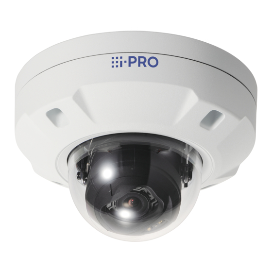
Network Camera
WV-X25700-V2L
Model No.
WV-X25600-V2L
WV-X25500-V3L
WV-X25300-V3L
About the user manuals
Product documentation is composed of the following documents.
• Installation Guide (this document): Provides information about "Precautions",
"Precautions for installation" and the installation method.
• Web Guide (Refer to the the link on the following product information website):
Includes installation videos, basic functions, and basic operation methods for this device.
• User manual (Refer to the link on the following product information website):
This section describes the software operating instructions common to each model.
https://i-pro.com/products_and_solutions/en/surveillance/documentation-database
"<Control No.: C****>" used in these documents should be used to search for
information on our technical information website
(https://i-pro.com/products_and_solutions/en/surveillance/learning-and-support/
knowledge-base/technical-information) and will guide you to the right information.
• Before attempting to connect or operate this product, please read these instructions
carefully and save Important Safety Instructions leaflet for future use.
• microSDXC/ microSDHC/ microSD memory card is described as microSD memory card.
• The external appearance and other parts shown in this manual may differ from the actual product within the
scope that will not interfere with normal use due to improvement of the product.
Tokyo, Japan
https://www.i-pro.com/
© i-PRO Co., Ltd. 2023
For professional use only
1
Outdoor use
WV-X25700-V2L
Authorised Representative in EU:
i-PRO EMEA B.V.
Laarderhoogtweg 25, 1101 EB
Amsterdam, Netherlands
i-PRO EMEA B.V. UK Branch
1010 Cambourne Business Park,
Cambridgeshire CB23 6DP
N1223-0
PGQP3705ZA
Advertisement
Table of Contents

Related Manuals for i-PRO WV-X25700-V2L


Summary of Contents for i-PRO WV-X25700-V2L
- Page 1 Authorised Representative in EU: i-PRO EMEA B.V. Laarderhoogtweg 25, 1101 EB Amsterdam, Netherlands Tokyo, Japan i-PRO EMEA B.V. UK Branch https://www.i-pro.com/ 1010 Cambourne Business Park, Cambridgeshire CB23 6DP N1223-0 © i-PRO Co., Ltd. 2023...
- Page 2 This equipment generates, uses, and can Trade name : i-PRO radiate radio frequency energy and, if not installed Model No. : WV-X25700-V2L, WV-X25600-V2L and used in accordance with the instruction man- WV-X25500-V3L, WV-X25300-V3L ual, may cause harmful interference to radio com- Responsible Party : munications.
- Page 3 In order to prevent harm to people and damage to property, it explains what must be observed without fail. The safety statements common to all i-PRO network camera models are posted on the website linked from the twodimensional barcode on the right. Please be sure to confirm it.
-
Page 4: Precautions For Installation
Precautions for installation i-PRO Co., Ltd. assumes no responsibility for injuries or property damage resulting from failures arising out of improper installation or operation inconsistent with this documentation. „ In order to prevent injury, the product must be securely mounted to an installation surface according to Installation Guide. -
Page 5: Specifications
(excluding the attachment for the conduit) Mass: Approx. 1.1 kg {2.43 lbs} (excluding the attachment for the conduit) Main body: Finish: Aluminum die cast, i-PRO white Outer fixing screws: Stainless steel (Corrosion-resistant treatment) Dome cover: PC resin, Clear (with ClearSight coating) Others: Tamper-resistant enclosure* *1 Refer to our technical information website <Control No.: C0106>... -
Page 6: Standard Accessories
Standard accessories Important Safety Instructions ......1 pc. Bit ×1(Hex wrench, Grommet ×2 screw size 6.35 mm Attachment plate ×1 {1/4 inches} T20) (of them, 1 for spare) Fixing screw for attachment plate (M4 x 8 mm {5/16 inches}) ×5 Attachment for the conduit x1 (of them, 1 for spare) Rain wash coating label ×1... - Page 7 Installation Procedure See Web Guide Parts and functions Dome cover Enclosure Base cover Side cable access hole Conduit connection part (The female thread for conduit is compliant with ANSI NPSM (parallel pipe threads) 3/4 or ISO 228-1 (parallel pipe threads) G3/4.) Attachment for the conduit...
- Page 8 SD ON/OFF button : Lights off ① ② A click sound is heard. • User manual [Indicator] All LEDs forced to turn off • User manual “Format” • It is recommended to use a microSD memory card for i-PRO devices.
- Page 9 Step 1 Preparations „ Remove the enclosure (common) Bit (accessory) Installed auxiliary wire „ Remove the cable for easy kitting (common) Cable for easy kitting Do not use for actual installation.
- Page 10 „ When wiring on the side or using the attachment for conduit „ When using a RJ45 Ethernet cable (WV-QCA500A: option) RJ45 Ethernet cable (WV-QCA500A) ① ②...
- Page 11 „ When using an I/O cable (WV-QCA501A:option) Inside Outside...
- Page 12 Step 2 „ When installing with the base bracket (WV-QJB501-W) M4 (4 pcs.) (locally procured) Minimum pull-out strength: 196 N {44 lbf} (per 1 pc.) M4 × 8 mm {5/16 inches} (4 pcs.) (accessory of WV-QJB501-W) Recommended tightening torque: 0.78 N·m {0.58 lbf·ft} „...
- Page 13 Step 2 (continued) „ When fixing the camera on the installation surface after determining the camera direction 93 mm {3-21/32 inches} 116.5 mm {4-19/32 inches} 46 mm {1-13/16 inches} ø25.4 mm {ø1 inch} 23.8 mm {15/16 inches} 83.5 mm {3-9/32 inches} ø4 mm {5/32 inches} ×6 FRONT...
- Page 14 „ When adjusting the camera direction after installing the camera 46 mm {1-13/16 inches} ø73 mm {2-7/8 inches} 83.5 mm {3-9/32 inches} ø4 mm {5/32 inches} ×4 FRONT M4 (4 pcs.) (locally procured) Minimum pull-out strength: 196 N {44 lbf} (per 1 pc.) Note: •...
- Page 15 Step 3 RJ45 cap (accessory) Inside Grommet (accessory) Center Outside Reuse ø5 mm to ø8.5 mm {ø3/16 inches to ø11/32 inches} RJ45 Ethernet (PoE+) category 5e or better, straight, 4 pairs (8 pins) <100 m {328 feet} Outside Inside 150 mm {5-29/32 inches}...
- Page 16 Step 4 RJ45 Ethernet (PoE+) category 5e or better, straight, 4 pairs (8 pins) <100 m {328 feet} I/O cable WV-QCA501A (option) < 1 m {3.28 feet} (Mic) Audio in < 10 m {32.8 feet} (Line) (white) Audio out < 10 m {32.8 feet} (black) 4P alarm cable GND (black)
- Page 17 Step 4 (continued) „ Connect the RJ45 Ethernet cable to the camera. Step 3 Inside Outside...
- Page 18 Step 5 „ Check the installation direction of the camera. Ceiling FRONT Wall...
- Page 19 * The following are descriptions (continued) Step 5 of how to install the camera on a ceiling as an example. Ground wire (locally procured) M3×6 mm {1/4 inches} Recommended tightening torque: 0.69 N·m {0.51 lbf·ft} OPEN • Technical information website “Countermeasure for Lightning Surge”...
- Page 20 * The following are descriptions of how Step 5 (continued) to install the camera on a ceiling as an example. 0.78 N·m {0.58 lbf·ft} Outside Inside...
- Page 21 →Power On (12 V DC/PoE+) Step 6 If there is a protection film on the lens, remove it. Ceiling WIDE+AF TELE+AF 0.59 N·m {0.44 lbf·ft} Projection of the base cover (2 places) Wire hook ① ② ③ ③ Installed auxiliary wire 0.78 N·m {0.58 lbf·ft} When using an I/O cable...
- Page 22 Wall 0.59 N·m {0.44 lbf·ft} IR LED TELE+AF WIDE+AF • User manual “Image rotation → 180°” IR LED ③ Installed auxiliary wire 0.78 N·m {0.58 lbf·ft} ① ② Wire hook ③ Projection of the base cover (2 places) When using an I/O cable...
- Page 23 Step 7 • User manual “Focus adjustment” • Technical information website “IP Setting Software” <Control No.: C0123> “i-PRO Configuration Tool (iCT)” <Control No.: C0133> “Extra optical zoom” <Control No.: C0124> “Camera images that appear to overlap” <Control No.: C0128>...
-
Page 24: Guide D'installation
Cette section décrit les instructions d’utilisation du logiciel communes à chaque modèle. https://i-pro.com/products_and_solutions/en/surveillance/documentation-database “<Contrôle No. : C****>” utilisé dans ces documents devrait être employé pour rechercher l’information sur notre site Web d’informations techniques (https://i-pro. com/products_and_solutions/en/surveillance/learning-and-support/knowledge-base/ technical-information) et vous guidera vers la bonne information. - Page 25 Cet équipement génère, utilise Appellation commerciale: i-PRO et peut émettre une énergie de fréquences radio Nº de modèle: WV-X25700-V2L, WV-X25600-V2L et, s’il n’est pas installé et utilisé conformément WV-X25500-V3L, WV-X25300-V3L aux instructions, peut causer des interférences Partie responsable: nuisibles aux communications radio.
-
Page 26: Mesures De Précaution
Afin d’éviter les blessures corporelles et les dégâts à la propriété, elles expliquent ce qui doit être impérativement respecté. Les déclarations de sécurité communes à tous les modèles de caméra réseau i-PRO sont publiées sur le site Web accessible à partir du code-barres à deux dimensions à... - Page 27 „ Arrêter immédiatement l’utilisation quand quelque chose est erroné avec ce produit. Quand de la fumée se dégage du produit, qu’une odeur de fumée se dégage du produit ou que les surfaces extérieures du produit ont été abimées, le fait de continuer à utiliser le produit aura comme conséquence un incendie ou de faire une chute se traduisant par des blessures ou des dégâts à...
-
Page 28: Précautions D'installation
Précautions d’installation i-PRO Co., Ltd. n’assume aucune responsabilité en cas de dommages corporels ou matériels résultant de pannes dues à une installation incorrecte ou à une utilisation contraire à ce qui est indiqué dans cette documentation. „ Pour éviter que quelqu’un se blesse, ce produit doit être fixé solidement sur une surface d’installation conformément au Guide d’installation. - Page 29 „ Étiquette d’indication de classification d’équipement et de source d’énergie électrique Se référer à l’étiquette d’instructions collée en-dessous de cette unité quant aux informations de classifi- cation de l’équipement, de source d’alimentation et autres informations. „ VCCIについて この装置は、 クラスA機器です。 この装置を住宅環境で使用すると電波妨害を引き起こすことがあります。 この場合には使用者が適切な対策を講ずるよう要求されることがあります。...
-
Page 30: Caractéristiques Techniques
Masse: Environ 1,1 kg {2,43 lbs} (sans la fixation pour le conduit) Finition: Corps principal: Moulage d’aluminium, i-PRO blanche Vis de fixation d’installation externe: Acier inoxydable (traitement de résistance à la corrosion) Couvercle en dôme: Résine PC, transparent (avec revêtement de... -
Page 31: Accessoires Standard
Accessoires standard Important Safety Instructions ......1 él. Foret ×1 Œillet ×2 (Clé à six pans, taille de vis (parmi eux, 1 comme pièce Plaque de fixation ×1 6,35 mm {1/4 pouces} T20) de rechange) Vis de fixation de plaque de fixation (M4x8 mm {5/16 pouces}) ×5 Étiquette de revêtement... - Page 32 Procédure d’installation Voir le Guide Web Pièces et fonctions Couvercle en dôme Coffret extérieur Couvercle de base Ouverture latérale d’accès de câble Pièce de connexion de conduit (Le filetage femelle pour le conduit est conforme à la norme ANSI NPSM (filetages de tuyauterie parallèle) de 3/4 ou ISO 228-1 (filetages de tuyauterie parallèle) G3/4.)
- Page 33 Bouton SD ON/OFF : S’éteint ① ② Un clic se fait entendre. • Manuel d’instructions [Indicateurs] Arrêt forcé de toutes les LED • Manuel d’instructions “Formater” • Il est recommandé d’utiliser une carte de mémoire microSD pour les appareils i-PRO.
- Page 34 Étape 1 Préparatifs „ Retirer le coffret extérieur (commun) Foret (accessoire) Fil auxiliaire installé „ Retirer le câble pour un assemblage final facile (commun) Câble pour un assemblage final facile Ne pas l’utiliser pour une installation réelle.
- Page 35 „ Lors du câblage sur le côté ou de l’utilisation de la fixation pour le conduit „ Lors de l’utilisation d’un câble Ethernet RJ45 (WV-QCA500A: option) Câble Ethernet RJ45 (WV-QCA500A) ① ②...
- Page 36 „ Lors de l’utilisation d’un câble E/S (WV-QCA501A: option) À l’intérieur Extérieur...
- Page 37 Étape 2 „ Lors de l’installation avec une platine de fixation de base (WV-QJB501-W) M4 (4 él.) (à se procurer localement) Capacité de dégagement minimum exigée: 196 N {44 lbf} (par 1 él.) (M4 × 8 mm {5/16 pouces} (4 él.) (accessoire du WV-QJB501-W) Couple de serrage recommandé: 0,78 N·m {0,58 lbf·ft} „...
- Page 38 Étape 2 (suite) „ Lors de la fixation de la caméra vidéo sur la surface d’installation après avoir déterminé la direction de la caméra 116,5 mm 93 mm {3-21/32 pouces} {4-19/32 pouces} 46 mm {1-13/16 pouces} ø25,4 mm {ø1 pouce} 23,8 mm {15/16 pouces} 83,5 mm...
- Page 39 „ Lors du réglage de la direction de la caméra après son installation 46 mm {1-13/16 pouces} ø73 mm {2-7/8 pouces} 83,5 mm {3-9/32 pouces} ø4 mm {5/32 pouces} ×4 AVANT M4 (4 él.) (à se procurer localement) Capacité de dégagement minimum exigée: 196 N {44 lbf} (par 1 él.) Remarque: •...
- Page 40 Étape 3 Capuchon RJ45 (accessoire) Œillet (accessoire) À l’intérieur Centre Extérieur Réutilisation ø5mm à 8,5 mm {ø3/16 pouces à ø11/32 pouces} Ethernet RJ45 (PoE+) catégorie 5e ou supérieure, fils rectilignes, 4 paires (8 broches) < 100 m {328 feet} Extérieur À...
- Page 41 Étape 4 Ethernet RJ45 (PoE+), catégorie 5e ou supérieure, fils rectilignes, 4 paires (8 broches) < 100 m {328 feet} Câble E/S WV-QCA501A (option) < 1 m {3,28 feet} (Mic) Entrée audio < 10 m {32,8 feet} (Ligne) (blanc) Sortie audio <...
- Page 42 Étape 4 (suite) „ Connectez le câble Ethernet RJ45 à la caméra vidéo. Étape 3 À l’intérieur Extérieur...
- Page 43 Étape 5 „ Vérifiez la direction d’installation de la caméra vidéo. Plafond AVANT Murale HAUT...
- Page 44 Étape 5 (suite) * L’exemple suivant décrit comment installer la caméra vidéo au plafond. Fil de terre (à se procurer localement) M3×6 mm {1/4 pouces} Couple de serrage recommandé: 0,69 N·m {0,51 lbf·ft}) OPEN • Site Web d’informations techniques “Countermeasure for Lightning Surge” <Contrôle No.: C0121>...
- Page 45 Étape 5 (suite) * L’exemple suivant décrit comment installer la caméra vidéo au plafond. 0,78 N·m {0,58 lbf·ft} Extérieur À l’intérieur...
- Page 46 → Mise sous tension (12 V c.c./PoE+) Étape 6 S’il y a un film de protection sur l’objectif, le retirer. Plafond WIDE+AF TELE+AF 0,59 N·m {0,44 lbf·ft} Projection du couvercle de base (2 endroits) Crochet de câble ① ② ③ ③...
- Page 47 Murale 0,59 N·m Diode électro- {0,44 lbf·ft} luminescente à lumière infrarouge TELE+AF WIDE+AF • Manuel d’utilisation Diode “Rotation d’image → 180°” électrolu- minescente à lumière infrarouge ③ Fil auxiliaire installé 0,78 N·m {0,58 lbf·ft} ① ② Crochet de câble ③ Projection du couvercle de base (2 endroits) Lors de l’utilisation d’un câble E/S...
- Page 48 Étape 7 • Manuel d’utilisation “Réglage de zoom” • Site Web des informations techniques “IP Setting Software” <Contrôle No.: C0123> “i-PRO Configuration Tool(iCT)” <Contrôle No.: C0133> “Extra optical zoom” <Contrôle No.: C0124> “Camera images that appear to overlap” <Contrôle No.: C0128>...
- Page 49 Modelle gelten. https://i-pro.com/products_and_solutions/en/surveillance/documentation-database Die in diesen Dokumenten verwendete “<Kontroll-Nr.: C****>” kann zur Suche auf unserer Website für technische Informationen (https://i-pro.com/products_and_ solutions/en/surveillance/learning-and-support/knowledge-base/technical-information) verwendet werden und leitet Sie zu den richtigen Informationen weiter. • Bitte lesen Sie diese Bedienungsanleitung vor dem Anschließen und der Inbetriebnahme dieses Produkts aufmerksam durch und speichern Sie das Merkblatt “Important Safety Instructions”...
- Page 50 Entsorgung von Altgeräten und Batterien Nur für die Europäische Union und Länder mit Recyclingsystemen Dieses Symbol, auf den Produkten, der Verpackung und/oder den Begleitdokumenten, bedeutet, dass gebrauchte elektrische und elektronische Produkte sowie Batterien nicht in den allgemeinen Hausmüll gegeben werden dürfen. Bitte führen Sie alte Produkte und verbrauchte Batterien zur Behandlung, Aufarbeitung bzw.
- Page 51 Um Personen- und Sachschäden zu vermeiden, wird darin erklärt, was unbedingt zu beachten ist. Die Sicherheitshinweise, die für alle Netzwerkka- meramodelle von i-PRO gelten, finden Sie auf der Website, die über den zweidimensionalen Barcode auf der rechten Seite verlinkt ist. Bitte achten Sie darauf, sie zu konsultieren.
-
Page 52: Vorsichtsmaßnahmen Zur Installation
Vorsichtsmaßnahmen zur Installation i-PRO Co., Ltd. übernimmt keine Verantwortung für Verletzungen oder Sachschäden, die aus der Installation oder Bedienung resultieren, die nicht wie in dieser Dokumentation beschrieben ausgeführt werden. „ Das Produkt muss entsprechend dem Installationshandbuch sicher an einer Installationsfläche befestigt werden, um eine Verletzung zu vermeiden. -
Page 53: Technische Daten
ø154 mm x 105 mm (H) Dome-Radius 42 mm (ohne Befestigung für das Kabelrohr) Masse: Ca. 1,1 kg (ohne Befestigung für das Kabelrohr) Lackierung: Gehäuse: Aluminium-Druckguss, i-PRO Weiß Äußere Befestigungsschrauben: Edelstahl (Korrosionsbeständige Behandlung) Glockenabdeckung: PC-Harz, Clear (mit ClearSight-Beschichtung) Sonstiges: Manipulationssicheres Gehäuse* *1 Weitere Informationen über die Stromversorgung und Leistungsaufnahme finden Sie auf unserer... - Page 54 Standardzubehör Important Safety Instructions ......1 St. Einsatz ×1 (Sechskantschlüssel, Halteplatte ×1 Weite 6,35 mm T20) Tülle ×2 (einschl. 1 Reserve) Befestigungsschraube für Halteplatte (M4 × 8 mm) ×5 Regenwasserabweisendes Befestigung für das Kabelrohr x1 (einschl. 1 Reserve) Etikett ×1 Kabel für einfache Schablone ×1 RJ45-Kappe ×1...
-
Page 55: Teile Und Funktionen
Installationsverfahren Siehe Web-Anleitung Teile und Funktionen Glockenabdeckung Gehäuse Sockelabdeckung Seitliche Kabeldurchführung Kabelrohranschlussbereich (Das Innengewinde für das Kabelrohr entspricht ANSI NPSM (Parallelgewinde) 3/4 oder ISO 228-1 (Parallelgewinde) G3/4.) Befestigung für das Kabelrohr... - Page 56 INITIAL SET-Taste TELE+AF-Taste WIDE+AF-Taste : Leuchtet : Blinkt SD ON/OFF-Taste : Erlischt ① ② Es ertönt ein Klickgeräusch. • User manual [Indicator] Alle LEDs werden zwangsweise ausgeschaltet • User manual “Format” • Für die i-PRO-Geräte wird die Verwendung einer microSD-Speicherkarte empfohlen.
- Page 57 Schritt 1 Vorbereitungen „ Entfernen Sie das Gehäuse (Gemeinsam) Einsatz (Zubehör) Haltedraht „ Das Kabel für einfache Installation entfernen (Gemeinsam) Kabel für einfache Installation Verwenden Sie es nicht für die aktuelle Installation.
- Page 58 „ Bei Verkabelung an der Seite oder bei Verwendung des Befestigung für das Kabelrohr „ Bei Verwendung eines RJ45-Ethernetkabels (WV-QCA500A: Option) RJ45-Ethernetkabel (WV-QCA500A) ① ②...
- Page 59 „ Bei Verwendung eines E/A-Kabels (WV-QCA501A: Option) Innen Außen...
- Page 60 Schritt 2 „ Bei Installation mit der Sockelhalterung (WV-QJB501-W) M4 (4 St.) (vor Ort zu beschaffen) Mindestausreißfestigkeit: 196 N (pro 1 St.) M4 × 8 mm (4 St.) (Zubehör der WV-QJB501-W) Empfohlenes Anzugsmoment: 0,78 N·m „ Bei Installation mit einer Zweifach-Gangbox/ Anschlussdose M4 (4 St.) (vor Ort zu beschaffen) Mindestausreißfestigkeit:...
- Page 61 Schritt 2 (Fortsetzung) „ Bei Befestigung der Kamera an der Installationsfläche nach der Bestimmung der Richtung der Kamera 93 mm 116,5 mm 46 mm ø25,4 mm 23,8 mm 83,5 mm ø4 mm×6 VORNE M4 (4 St.) (vor Ort zu beschaffen) Mindestausreißfestigkeit: 196 N (pro 1 St.) M4 (6 St.) (vor Ort zu beschaffen)
- Page 62 „ Bei Einstellung der Richtung der Kamera nach der Installation der Kamera 46 mm ø73 mm 83,5 mm ø4 mm×4 VORNE M4 (4 St.) (vor Ort zu beschaffen) Mindestausreißfestigkeit: 196 N (pro 1 St.) Anmerkung: • Die Kamera kann in jeder Richtung installiert werden. VORNE VORNE...
- Page 63 Schritt 3 RJ45-Kappe (Zubehör) Innen Tülle (Zubehör) Mitte Außen Wiederverwenden ø5 mm - ø8,5 mm RJ45 Ethernet (PoE+) Kategorie 5e oder besser, geradlinig, 4 Leiterpaare (8 Pins) <100 m Außen Innen 150 mm...
- Page 64 Schritt 4 RJ45-Ethernetkabel (PoE+), Kategorie 5e oder besser, geradlinig, 4 Leiterpaare (8 Pins) < 100 m E/A-Kabel WV-QCA501A (Option) < 1 m (Mikro) Audio Ein < 10 m (Leitung) (Weiß) Audio Aus < 10 m (Schwarz) 4-poliges Alarmkabel GND (Schwarz) EXT I/O (Zubehör der WV-QCA501A) ALARM IN3 (Grau)
- Page 65 Schritt 4 (Fortsetzung) „ Schließen Sie das RJ45-Ethernetkabel an der Kamera an. Schritt 3 Innen Außen...
- Page 66 Schritt 5 „ Überprüfen Sie die Installationsrichtung der Kamera. Decke VORNE Wand OBEN...
- Page 67 * Im Folgenden wird beschrieben, Schritt 5 (Fortsetzung) wie die Kamera beispielsweise an einer Decke installiert wird. Erdungsleitung (vor Ort zu beschaffen) M3×6 mm Empfohlenes Anzugsmoment: 0,69 N·m OPEN • Website für technische Informationen “Countermeasure for Lightning Surge” <Kontroll-Nr.: C0121>...
- Page 68 * Im Folgenden wird beschrieben, Schritt 5 (Fortsetzung) wie die Kamera beispielsweise an einer Decke installiert wird. 0,78 N·m Außen Innen...
- Page 69 → Strom Ein (12 V Gleichstrom/PoE+) Schritt 6 Wenn sich eine Schutzfolie auf dem Objektiv befindet, entfernen Sie diese. Decke WIDE+AF TELE+AF 0,59 N·m Vorsprung des Sockelabdeckung (2 Stellen) Drahthaken ① ② ③ ③ Haltedraht 0,78 N·m Bei Verwendung eines E/A-Kabels...
- Page 70 Wand 0,59 N·m IR LED TELE+AF WIDE+AF • User manual “Image rotation → 180°” IR LED ③ Haltedraht 0,78 N·m ① ② Drahthaken ③ Vorsprung des Sockelabdeckung (2 Stellen) Bei Verwendung eines E/A-Kabels...
- Page 71 Schritt 7 • User manual “Focus adjustment” • Website für technische Informationen “IP Setting Software” <Kontroll-Nr.: C0123> oder “i-PRO Configuration Tool(iCT)” <Kontroll-Nr.: C0133> “Extra optical zoom” <Kontroll-Nr.: C0124> “Camera images that appear to overlap” <Kontroll-Nr.: C0128>...
- Page 72 “<Control No.: C****>” usato in questi documenti dovrebbe essere utilizzato per la ricerca di informazioni sul nostro sito web di informazioni tecniche (https://i-pro.com/ products_and_solutions/en/surveillance/learning-and-support/knowledge-base/ technical-information) e condurrà alla corretta informazione. • Prima di provare a collegare o utilizzare questo prodotto, leggere attentamente queste istruzioni e conservare l’opuscolo “Important Safety Instructions”...
- Page 73 Smaltimento di vecchie apparecchiature e batterie usate Solo per Unione Europea e Nazioni con sistemi di raccolta e smaltimento Questi simboli sui prodotti, sull’imballaggio e/o sulle documentazioni o manuali accompagnanti i prodotti indicano che i prodotti elettrici, elettronici e le batterie usate non devono essere smaltiti come rifiuti urbani ma deve essere effettuata una raccolta separata.
- Page 74 Spiegano quali disposizioni osservare obbligatoriamente per evitare lesioni alle persone e danni materiali. Le dichiarazioni sulla sicurezza comuni a tutti i modelli di telecamera di rete i-PRO sono pubblicate sul sito web accessibile dal codice a barre bidimensionale sulla destra. Non esitare a consultarle.
-
Page 75: Precauzioni Per L'installazione
Precauzioni per l’installazione i-PRO Co., Ltd. non potrà essere considerata responsabile per danni patrimoniali e/o non patrimoniali a cose e/o persone derivanti da installazione o funzionamento eseguiti in modo non conforme al presente documento. „ Al fine di prevenire ferite, questo prodotto deve essere montato saldamente su una superficie di installazione in conformità... -
Page 76: Dati Tecnici
Raggio della cupola 42 mm (Esclusa l’attacco per la tubazione) Peso: Circa 1,1 kg (Esclusa l’attacco per la tubazione) Finitura: Corpo principale: Alluminio pressofuso, i-PRO bianco Viti di fissaggio esterne: Acciaio inossidabile (trattamento anticorrosione) Coperchio a cupola: Resina PC, trasparente (con rivestimento ClearSight) Altro: Involucro a prova di manomissione* *1 Far riferimento al nostro sito web di informazioni tecniche <Control No.: C0106>... -
Page 77: Accessori Standard
Accessori standard Important Safety Instructions ......1 pz. Punta ×1 (chiave esagonale, dimensione Passacavo ×2 Piastra di fissaggio x1 della vite 6,35 mm T20) (di cui 1 di scorta) Vite di fissaggio per piastra di fissaggio (M4 × 8 mm) Etichetta del rivestimento Attacco per la tubazione x1 ×5 (di cui 1 di scorta) antipioggia ×1... - Page 78 Procedura di installazione Vedere Guida web Parti e funzioni Coperchio a cupola Involucro Coperchio della base Foro di accesso dei cavi laterale Parte di collegamento della tubazione (La filettatura femmina per tubazioni è conforme a ANSI NPSM (filettatura per tubi cilindric) 3/4 o ISO 228-1 (filettatura per tubi cilindric) G3/4.) Attacco per la tubazione...
- Page 79 : Lampeggia Tasto SD ON/OFF : Spento ① ② Si sente un clic. • User manual [Indicator] Spegnimento forzato di tutti i LED • User manual “Format” • Si consiglia di utilizzare una scheda di memoria microSD per dispositivi i-PRO.
- Page 80 Passaggio 1 Preparativi „ Rimuovere l’involucro (comune) Punta (accessorio) Cavo ausiliario installato „ Rimuovere il cavo per montaggio facile (comune) Cavo per montaggio facile Non utilizzare per l’installazione effettiva.
- Page 81 „ Quando si esegue il cablaggio laterale o si utilizza l’attacco per la tubazione „ Quando si utilizza un cavo Ethernet RJ45 (WV-QCA501A: optional) Cavo Ethernet RJ45 (WV-QCA500A) ① ②...
- Page 82 „ Quando si utilizza un cavo I/O (WV-QCA501A: optional) Interno Esterno...
- Page 83 Passaggio 2 „ In caso di installazione con la staffa base (WV-QJB501-W) M4 (4 pz.) (da procurarsi localmente) Resistenza alla trazione minima: 196 N (per 1 pz.) M4 × 8 mm (4 pz.) (accessorio della WV-QJB501-W) Coppia di torsione dell’avvitamento consigliata: 0,78 N·m „...
- Page 84 Passaggio 2 (continuazione) „ Quando si fissa la telecamera sulla superficie di installazione dopo aver determinato la direzione della telecamera 93 mm 116,5 mm 46 mm ø25,4 mm 23,8 mm 83,5 mm ø4 mm ×6 FRONTE M4 (4 pz.) (da procurarsi localmente) Resistenza alla trazione minima: 196 N (per 1 pz.) M4 (6 pz.) (da procurarsi localmente)
- Page 85 „ Quando si regola la direzione della telecamera dopo aver installato la telecamera 46 mm ø73 mm 83,5 mm ø4 mm ×4 FRONTE M4 (4 pz.) (da procurarsi localmente) Resistenza alla trazione minima: 196 N (per 1 pz.) Nota: • La telecamera può essere installata in qualsiasi direzione. FRONTE FRONTE...
- Page 86 Passaggio 3 Cappuccio RJ45 (accessorio) Interno Passacavo (accessorio) Centro Esterno Riutilizzo ø5 mm - ø8,5 mm Ethernet RJ45 (PoE+) Categoria 5e o superiore, dritto, 4 i doppini (8 pin) < 100 m Esterno Interno 150 mm...
- Page 87 Passaggio 4 Ethernet RJ45 (PoE+) categoria 5e o superiore, dritto, 4 i doppini (8 pin) < 100 m Cavo I/O WV-QCA501A (optional) < 1 m (Microfono) Ingresso audio < 10 m (Linea) (bianco) Uscita audio < 10 m (nero) Cavo dell’allarme a 4 pin GND (nero) EXT I/O (accessorio della WV-QCA501A)
- Page 88 Passaggio 4 (continuazione) „ Collegare il cavo Ethernet RJ45 alla telecamera. Passaggio 3 Interno Esterno...
-
Page 89: Parte Superiore
Passaggio 5 „ Controllare la direzione di installazione della telecamera. Soffitto FRONTE Parete PARTE SUPERIORE... - Page 90 * Di seguito sono riportate le Passaggio 5 (continuazione) descrizioni esemplificative che illustrano come installare la telecamera sul soffitto. Filo di massa (da procurarsi localmente) M3×6 mm Coppia di torsione dell’avvitamento consigliata: 0,69 N·m OPEN • Sito web di informazioni tecniche “Countermeasure for Lightning Surge”...
- Page 91 * Di seguito sono riportate le Passaggio 5 (continuazione) descrizioni esemplificative che illustrano come installare la telecamera sul soffitto. 0,78 N·m Esterno Interno...
- Page 92 → Accensione (12 V CC/PoE+) Passaggio 6 Se è presente una pellicola di protezione sull’obiettivo, rimuoverla. Soffitto WIDE+AF TELE+AF 0,59 N·m Sporgenza del coperchio della base (2 punti) Aggancio del cavo ① ② ③ ③ Cavo ausiliario installato 0,78 N·m Quando si utilizza un cavo I/O...
- Page 93 Parete 0,59 N·m IR LED TELE+AF WIDE+AF • User manual “Image rotation → 180°” IR LED ③ Cavo ausiliario installato 0,78 N·m ① ② Aggancio del cavo ③ Sporgenza del coperchio della base (2 punti) Quando si utilizza un cavo I/O...
- Page 94 Passaggio 7 • User manual “Focus adjustment” • Sito web di informazioni tecniche “IP Setting Software” <Control No.: C0123> “i-PRO Configuration Tool(iCT)” <Control No.: C0133> “Extra optical zoom” <Control No.: C0124> “Camera images that appear to overlap” <Control No.: C0128>...
-
Page 95: Guía De Instalación
El “<N.° de control: C****>” usado en estos documentos debe utilizarse para buscar información en nuestro sitio web de información técnica (https://i-pro.com/products_ and_solutions/en/surveillance/learning-and-support/knowledge-base/technical- information) y le guiará a la información correcta. • Antes de conectar o poner en funcionamiento este aparato, lea atentamente estas instrucciones y conserve el folleto “Important Safety Instructions”... - Page 96 Eliminación de Aparatos Viejos y de Pilas y Baterías Solamente para la Unión Europea y países con sistemas de reciclado Estos símbolos en los productos, su embalaje o en los documentos que los acompañen significan que los productos eléctricos y electrónicos y pilas y baterías usadas no deben mezclarse con los residuos domésticos.
- Page 97 Para evitar daños a las personas y a la propiedad, se explica lo que es imprescindible tener en cuenta. Las declaraciones de seguridad comunes a todos los modelos de cámaras de red i-PRO se publican en el sitio web vinculado desde el código de barras bidimensional de la derecha. Asegúrese de confirmarlo todo.
-
Page 98: Precauciones Para La Instalación
Precauciones para la instalación i-PRO Co., Ltd. no se hace responsable de lesiones o daños a la propiedad que resulten de fallos derivados de una incorrecta instalación o funcionamiento que no se ajuste con esta documentación. „ Con el fin de evitar lesiones, el producto debe ser instalado de forma segura en una superficie de instalación de acuerdo con la Guía de instalación. -
Page 99: Especificaciones
Radio del domo 42 mm (excluyendo la fijación para el conducto) Masa: Aprox. 1,1 kg (excluyendo la fijación para el conducto) Cuerpo principal: Acabado: Aluminio presofundido, blanco i-PRO Tornillos de fijación exteriores: Acero inoxidable (tratamiento resistente a la corrosión) Cubierta del domo:... -
Page 100: Accesorios Estándar
Accesorios estándar Important Safety Instructions ......1 pieza Broca ×1 (llave hexagonal, tamaño de Aislador ×2 Placa de fijación ×1 tornillo de 6,35 mm T20) (1 de ellas de repuesto) Tornillo de fijación para la placa de fijación (M4 × 8 mm) Etiqueta de revestimiento Fijación para el conducto x1 ×5 (1 de ellas de repuesto) - Page 101 Procedimiento de instalación Consulte la Guía web Partes y funciones Cubierta del domo Alojamiento Cubierta de la base Orificio de acceso de cables lateral Pieza de conexión del conducto (la rosca hembra para los conductos cumple las normas ANSI NPSM (para roscas de tubo paralelas) de 3/4 o ISO 228-1 (para roscas de tubo paralelas) de G3/4).
- Page 102 : Parpadea Botón SD ON/OFF : Se apaga ① ② Se oye un clic. • User manual [Indicator] Apagado forzoso de todos los LED • User manual “Format” • Se recomienda usar una tarjeta de memoria microSD para dispositivos i-PRO.
- Page 103 Paso 1 Preparativos „ Retire el alojamiento (común) Broca (accesorio) Cable auxiliar instalado „ Extraiga el cable para un fácil equipamiento (común) Cable para un fácil equipamiento No lo utilice para la instalación real.
- Page 104 „ Al realizar el cableado lateral o utilizar el fijación para el conducto „ Al usar un cable de Ethernet RJ45 (WV-QCA500A: opcional) Cable de Ethernet RJ45 (WV-QCA500A) ① ②...
- Page 105 „ Al usar un cable de E/S (WV-QCA501A: opcional) Dentro Exterior...
- Page 106 Paso 2 „ Al instalar con el ménsula de la base (WV-QJB501-W) M4 (4 piezas) (de venta en los establecimientos del ramo) Resistencia mínima al tiro hacia fuera: 196 N (por 1 pieza) M4 × 8 mm (4 piezas) (accesorio de WV-QJB501-W) Torsión de apriete recomendada: 0,78 N·m „...
- Page 107 Paso 2 (continuación) „ Al fijar la cámara en la superficie de instalación después de determinar la dirección de la cámara 93 mm 116,5 mm 46 mm 25,4 mmø 23,8 mm 83,5 mm 4 mmø ×6 FRENTE M4 (4 piezas) (de venta en los establecimientos del ramo) Resistencia mínima al tiro hacia fuera: 196 N (por 1 pieza)
- Page 108 „ Al ajustar la dirección de la cámara después de instalar la cámara 46 mm 73 mmø 83,5 mm 4 mmø ×4 FRENTE M4 (4 piezas) (de venta en los establecimientos del ramo) Resistencia mínima al tiro hacia fuera: Nota: 196 N (por 1 pieza) •...
- Page 109 Paso 3 Tapa RJ45 (accesorio) Dentro Aislador (accesorio) Central Exterior Reutilizar 5 mmø - 8,5 mmø Ethernet RJ45 (PoE+) categoría 5e o mejor, recto, 4 pares (8 clavijas) <100 m Exterior Dentro 150 mm...
- Page 110 Paso 4 Ethernet RJ45 (PoE+) categoría 5e o mejor, recto, 4 pares (8 clavijas) < 100 m Cable de E/S WV-QCA501A (opcional) < 1 m (micrófono) Entrada de audio < 10 m (línea) (blanco) Salida de audio < 10 m (negro) Cable de alarma de 4 contactos GND (negro)
- Page 111 Paso 4 (continuación) „ Conecte el cable de Ethernet RJ45 a la cámara. Paso 3 Dentro Exterior...
-
Page 112: Parte Superior
Paso 5 „ Compruebe la dirección de instalación de la cámara. Techo FRENTE Pared PARTE SUPERIOR... - Page 113 * A continuación se describe cómo Paso 5 (continuación) instalar la cámara en un techo a modo de ejemplo. Cable de tierra (de venta en los establecimientos del ramo) M3×6 mm Torsión de apriete recomendada: 0,69 N·m OPEN • Sitio web de información técnica “Countermeasure for Lightning Surge”...
- Page 114 * A continuación se describe cómo Paso 5 (continuación) instalar la cámara en un techo a modo de ejemplo. 0,78 N·m Exterior Dentro...
- Page 115 → Encendido (12 V CC/PoE+) Paso 6 Si hay película protectora en el objetivo, retírela. Techo WIDE+AF TELE+AF 0,59 N·m Saliente de la cubierta de la base (2 lugares) Gancho del cable ① ② ③ ③ Cable auxiliar instalado 0,78 N·m Al usar un cable de E/S...
- Page 116 Pared 0,59 N·m LED IR TELE+AF WIDE+AF • User manual “Image rotation → 180°” LED IR ③ Cable auxiliar instalado 0,78 N·m ① ② Gancho del cable ③ Saliente de la cubierta de la base (2 lugares) Al usar un cable de E/S...
- Page 117 Paso 7 • User manual “Focus adjustment” • Sitio web de información técnica “IP Setting Software” <N.º de control: C0123> “i-PRO Configuration Tool(iCT)” <N.º de control: C0133> “Extra optical zoom” <N.º de control: C0124> “Camera images that appear to overlap”...
-
Page 118: Руководство По Монтажу
с информацией о продукте): В этом разделе приведены инструкции по эксплуатации, общие для всех моделей. https://i-pro.com/products_and_solutions/en/surveillance/documentation-database “<Контрольный №: C****>”, используемый в этих документах, следует использовать для поиска информации на нашем веб-сайте технической информации (https://i-pro.com/ products_and_solutions/en/surveillance/learning-and-support/knowledge-base/technical- information) и нахождения нужной информации. • Прежде чем приступить к подсоединению или управлению настоящим изделием, следует... -
Page 119: Информация Об Изделии
6. полібромдефенілові ефіри (PBDE) – не перевищує 0,1 % ваги речовини або в концентрації до 1000 частин на мільйон. Информация об изделии Страна-производитель Сделано в Китае Название производителя i-PRO Co., Ltd. Местонахождение производителя 2-15-1 Конан, Минато-ку, Токио 108-6014 Япония Год/месяц производства Первая буква серийного номера изделия указывает две последние цифры года: пример) 2001: A, 2002: B, …... -
Page 120: Меры Предосторожности
Во избежание нанесения вреда людям и материального ущерба объясняются требования, которые необходимо неукоснительно соблюдать. Положения тех- ники безопасности, общие для всех моделей сетевых камер i-PRO, размещены на веб-сайте, ссылку на который содержит двухмерный штрих-код справа. Пожалуйста, не забудьте просмотреть его. -
Page 121: Меры Предосторожности При Монтаже
Меры предосторожности при монтаже i-PRO Co., Ltd. не несет ответственности за травмы и материальный ущерб, причиненные вследствие неправильной установки или эксплуатации не в соответствии с данной документацией. „ Чтобы предотвратить травмы, изделие должно быть надежно установлено на поверхности установки согласно руководству по монтажу. - Page 122 Купольный радиус 42 mm (за исключением крепления для трубки) Масса: Прибл. 1,1 kg (за исключением крепления для трубки) Отделка: Корпус камеры: Литой под давлением алюминий, i-PRO белый Наружные крепежные винты: Нержавеющая сталь (антикоррозионная обработка) Крышка купола: Смола ПК, Прозрачный (с покрытием ClearSight) Проч.: Износостойкий...
- Page 123 Стандартные аксессуары Important Safety Instructions ..........1 шт. Наконечник ×1 (шестигранный ключ, раз- Крепежная планка ×1 мер винта 6,35 mm T20) Втулка ×2 (1 из них запасной) Крепежный винт для крепежной планки (M4 × 8 mm) ×5 Этикетка водоотталкивающего Крепление для трубки x1 (1 из...
-
Page 124: Процесс Установки
Процесс установки См. веб-руководство Части и функции Крышка купола Корпус Крышка основания Отверстие доступа параллельного кабеля Деталь для подключения кабелепровода (Внутренняя резьба кабеле- провода соответствует ANSI NPSM (цилиндрической трубной резьбе) 3/4 или ISO 228-1 (цилиндрической трубной резьбе) G3/4.) Крепление для трубки... - Page 125 Кнопка INITIAL SET Кнопка TELE+AF Кнопка WIDE+AF : Горит : Мигает Кнопка SD ON/OFF : Гаснет ① ② Слышен звук щелчка. • User manual [Indicator] Все светодиоды принудительно выключаются • User manual “Format” • Для устройств i-PRO рекомендуется использовать карту памяти microSD.
- Page 126 Шаг 1 Подготовка „ Удалите корпус (общий) Наконечник (аксессуар) Установленный дополнительный провод „ Извлеките кабель для удобной комплектации (общий) Кабель для удобной комплектации Не используйте для фактической установки.
- Page 127 „ При монтаже проводки сбоку или использовании кронштейна для кабелепровода „ При использовании кабеля Ethernet RJ45 (WV-QCA500A: опция) Кабель Ethernet RJ45 (WV-QCA500A) ① ②...
- Page 128 „ При использовании кабеля ввода-вывода (WV-QCA501A: опция) Внутри Внешняя сторона...
- Page 129 Шаг 2 „ При установке с кронштейна для основания (WV-QJB501-W) M4 (4 шт.) (приобретаем. на месте) Миним. прочность на выдергивание: 196 N (на 1 шт.) M4 × 8 mm (4 шт.) (аксессуар WV-QJB501-W) Рекомендуемый крутящий момент при затяжке винтов: 0,78 N·m „...
- Page 130 Шаг 2 (продолжение) „ При фиксации камеры на монтажной поверхности после определения направления камеры 93 mm 116,5 mm 46 mm ø25,4 mm 23,8 mm 83,5 mm ø4 mm ×6 СПЕРЕДИ M4 (4 шт.) (приобретаем. на месте) Миним. прочность на выдергивание: 196 N (на...
- Page 131 „ При регулировки направления камеры после ее монтажа 46 mm ø73 mm 83,5 mm ø4 mm ×4 СПЕРЕДИ M4 (4 шт.) (приобретаем. на месте) Миним. прочность на выдергивание: 196 N (на 1 шт.) Замечание: • Камеру можно монтировать в любом направлении. СПЕРЕДИ...
- Page 132 Шаг 3 Колпачок RJ45 (аксессуар) Внутри Втулка (аксессуар) Центр Внешняя сторона Повторное использование ø5 mm - ø8,5 mm RJ45 Ethernet (PoE+) категории 5e и лучше, прямой, 4 пары (8 контактов) < 100 m Внешняя сторона Внутри 150 mm...
- Page 133 Шаг 4 RJ45 Ethernet (PoE+) категории 5e и лучше, прямой, 4 пары (8 контактов) < 100 m Кабель входа/выхода WV-QCA501A (опция) < 1 m (Микрофон) Аудиовход < 10 m (Линия) (белая) Аудиовыход < 10 m (черный) 4-контактный кабель сигнала тревоги GND (черный) EXT I/O (аксессуар...
- Page 134 Шаг 4 (продолжение) „ Подсоедините кабель Ethernet RJ45 к камере. Шаг 3 Внутри Внешняя сторона...
- Page 135 Шаг 5 „ Проверьте направление монтажа камеры. Потолок СПЕРЕДИ Стена ВВЕРХ...
- Page 136 * Ниже в качестве примера Шаг 5 (продолжение) приведено описание порядка потолочного монтажа камеры. Выполните заземление (приобретаем. на месте) M3×6 mm Рекомендуемый крутящий момент при затяжке винтов: 0,69 N·m OPEN • Веб-сайт технической информации “Countermeasure for Lightning Surge” <Контрольный №: C0121>...
- Page 137 * Ниже в качестве примера Шаг 5 (продолжение) приведено описание порядка потолочного монтажа камеры. 0,78 N·m Внешняя сторона Внутри...
- Page 138 →Включить Питание (Пост.т. 12 V/PoE+) Шаг 6 Если на объективе имеется защитная пленка, снимите ее. Потолок WIDE+AF TELE+AF 0,59 N·m Выступ нижней крышки (в 2 местах) Крюк для провода ① ② ③ ③ Установленный дополнительный провод 0,78 N·m При использовании кабеля ввода/вывода...
- Page 139 Стена 0,59 N·m ИК светодиод TELE+AF WIDE+AF • User manual “Image rotation → 180°” ИК светодиод ③ Установленный допол- нительный провод 0,78 N·m ① ② Крюк для провода ③ Выступ нижней крышки (в 2 местах) При использовании кабеля ввода/вывода...
- Page 140 Шаг 7 • User manual “Focus adjustment” • Веб-сайт технической информации “IP Setting Software” <Контрольный №: C0123> или “i-PRO Configuration Tool(iCT)” <Контрольный №: C0133> “Extra optical zoom” <Контрольный №: C0124> “Camera images that appear to overlap” <Контрольный №: C0128>...
Need help?
Do you have a question about the WV-X25700-V2L and is the answer not in the manual?
Questions and answers