Page 1
Important Information
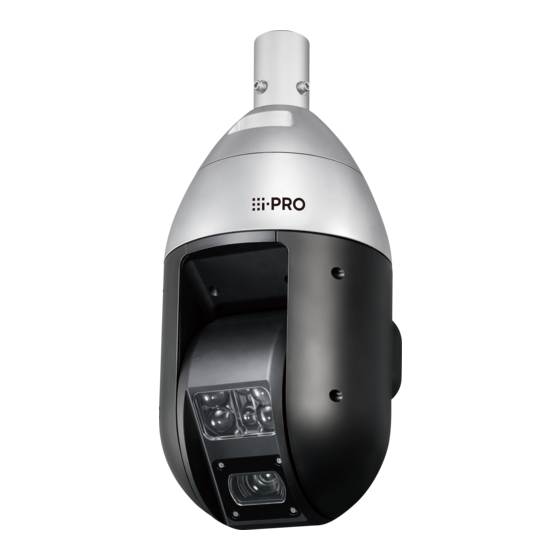
 Network Camera WV-X6533LN, WV-S6532LN Model No. WV-X6533LNS, WV-S6532LNS (Heavy salt damage resistance) (Heavy salt damage resistance) WV-X6533LN * For information about the installation tasks, refer to the provided Installation Guide. For information about how to perform the settings and how to operate the camera, refer to the Operating Instructions on the following our support website.
Contents Limitation of liability ........................3 Disclaimer of warranty ........................3 Preface ............................4 About notations ..........................4 Main functions ..........................4 About the user manuals ........................ 6 System requirements for a PC ...................... 6 Trademarks and registered trademarks..................7 Open Source Software ........................
IMPROVEMENTS OF THIS PUBLICATION AND/OR THE CORRESPONDING PRODUCT (S). Disclaimer of warranty IN NO EVENT SHALL i-PRO Co., Ltd. BE LIABLE TO ANY PARTY OR ANY PERSON, EXCEPT FOR REPLACEMENT OR REASONABLE MAINTENANCE OF THE PRODUCT, FOR THE CASES, INCLUDING BUT NOT LIMITED TO BELOW:...
The following notations are used when describing the functions limited for specified models. The functions without the notations are supported by all models. X6533 The functions with this notation are available when using the model WV-X6533LN, WV-X6533LNS. The functions with this notation are available when using the model WV-S6532LN, WV-S6532LNS. S6532...
Page 5
*1 When using a 24V AC power supply or the tested PoE injector. The irradiation distance is 150m {Approx. 500 ft} when PoE+ device is used. For the latest information about the tested PoE injector, refer to our support website (https://i-pro.com/global/en/surveillance/training_support/ support/technical_information <Control No.: C0116>).
Reader or Acrobat Reader (It is necessary to view the PDF file.) *1 In order to view camera images with Internet Explorer, we recommend using the hardware decode function. For details, refer to our support website (https://i-pro.com/global/en/surveillance/training_support/support/technical_information <Control No.: C0313>).
IMPORTANT: • For information on the operation verification of the supported operating systems and web browsers, refer to our support website at https://i-pro.com/global/en/surveillance/training_ support/support/technical_information <Control No.: C0104, C0122>. • When using a PC that does not meet the above requirements, displaying of images may become slower or the web browser may become inoperable.
Copyright Except for open source software licensed under GPL/LGPL and so on, distributing, copying, disas- sembling, reverse compiling and reverse engineering of the software provided with this product are all expressly prohibited. In addition, exporting any software provided with this product violating export laws is prohibited.
Precautions Do not insert any foreign objects. Do not install this product on a place that Fire or electrical shock may be caused if water is greatly influenced by wind. or any foreign objects, such as metal objects, Installation on a place where the wind speed is enter inside the unit.
Page 10
Do not install this product in locations subject to vibration. Loosening of mounting screws or bolts may cause a fall of the product resulting in injury or accidents. : Caution, infrared radiation : Direct current symbol : Alternating current symbol This illustration represents WV-X6533LN...
Page 11
[Precautions for use] When an error is detected, this product will restart automatically. When the product is accessible from the Internet This product will be inoperable for around 2 minutes after the restart just as when the To prevent unauthorized access, note the fol- power is turned on.
Page 12
About the CMOS image sensor • If dirt cannot be wiped off with a damp • When continuously shooting a bright light cloth, use a neutral detergent for kitchen utensils, and sufficiently rinse off the deter- source such as a spotlight, the color filter of the CMOS image sensor may become gent.
Page 13
Product disposal/transfer Refer to our support website (https://i-pro.com/global/en/surveillance/ Data saved on this product or a storage device training_support/support/technical_ used with this product may lead to personal information <Control No.: C0125>) for slip information leakage. When it is necessary to ring information.
Precautions for installation i-PRO Co., Ltd. assumes no responsibility for injuries or property damage resulting from failures arising out of improper installation or operation inconsistent with this documentation. For information about the installation tasks, refer to the provided Installation Guide.
Page 15
• Locations near coasts directly subjected to installed and operated in an environment where sea breezes, <WV-X6533LN / WV-S6532LN only> the temperature is below –30 °C {–22 °F}. In or locations subject to corrosive gases such a case, wait approximately 2 hours or such as from hot springs, volcanic regions, more until the camera is warmed up.
Page 16
(Always consider the installation place carefully. connect the metal pipe with grounding). • Refer to our support website (https://i-pro.com/global/en/surveillance/ Radio disturbance training_support/support/technical_ Noise may appear in video or audio near a information <Control No.: C0109>) for strong electric field from a TV or radio antenna, image examples and measures to take.
Parts and functions 【Whole unit】 This illustration represents WV-X6533LN Cable cover (accessory) Safety wire IR LED Light Camera arm unit SD slot cover Front panel* Camera unit 【SD slot cover portion】 INITIAL SET switch LINK indicator (OFF⇔ON) ACT indicator SD ERROR indicator...
Page 18
④ 8P alarm ③ cable (accessory) This illustration represents WV-X6533LN ①RJ45 (female) Network cable Connect an Ethernet cable (category 5e or better, straight) to the network connector. IMPORTANT: • Use all 4 pairs (8 pins) of the Ethernet cable. • The maximum length of the Ethernet cable (locally procured) is 100 m {Approx. 328 ft}.
Page 19
②Power supply terminal (24 V AC) / 24 V AC power supply connector kit (accessory) Caution: • A READILY ACCESSIBLE DISCONNECT DEVICE SHALL BE INCORPORATED TO THE EQUIPMENT POWERED BY 24 V AC POWER SUPPLY. • ONLY CONNECT 24 V AC CLASS 2 POWER SUPPLY (UL 1310/CSA 223) or LIMITED POWER SOURCE (IEC/EN/UL/CSA 60950-1).
Page 20
Note: • The audio output can be switched to the monitor output. Refer to the Operating Instructions on our support website for descriptions of how to switch the output. • The video output is set to NTSC in the default settings of the camera. If you want to change the video output setting to PAL, refer to the Operating Instructions on our support website.
Page 21
Connection example Before starting the installation, check the entire system configuration. When connecting with a PC directly <Required cable> Ethernet cable (category 5e or better, cross) Powered speaker Ethernet cable (category 5e or better, cross) ➡ 24 V AC power supply Plug-in power type microphone...
Page 22
Connecting to a network using a PoE+ hub /device when the temperature is –30 °C {–22 °F} or less When the temperature is –30 °C {–22 °F} or less, use a 24 V AC power supply or a tested PoE injector.
Page 23
■ Indicators and Switch ②LINK indicator ①INITIAL SET switch ③ACT indicator (OFF⇔ON) ④SD ERROR indicator SD slot ①INITIAL SET switch Use the INITIAL SET switch to reset the settings of the camera to the default. IMPORTANT: • When the camera is initialized, the settings including the network settings will be initialized. Before initializing the settings, it is recommended to write down the settings in advance.
Page 24
Step 6 Step 7 If the [Run] button next to [IP Setting Software] Confirm that the administrator registration win- is clicked, information such as the MAC address dow is displayed. and the IP address, etc. of the camera are dis- played in the [IP Setting Software] screen.
Note: Refer to the Operating Instructions on our support website for further information about the SD memory card settings. Refer to our support website (https://i-pro.com/global/en/surveillance/training_support/support/ technical_information <Control No.: C0107>) for latest information about the compatible SD memory cards.
Page 26
【2】 Insert an SD memory card. Step 1 Open the SD slot cover SD slot cover fixing screws Loosen 2 SD slot cover fixing screws (M4) at the rear part of the camera unit using a Phillips screwdriver, and open the SD slot cover. Step 2 SD slot cover Insert an SD memory card...
Page 27
■ Remove an SD memory card • Even when removing an SD memory card, turn off the power of the camera. • When it is difficult to turn off the power of the camera, always put this camera in the “Insert/ Remove SD memory card”...
Troubleshooting Before asking for repairs, check the symptoms with the following table. Contact your dealer if a problem cannot be solved even after checking and trying the solution in the table or a problem is not described below. Reference Symptom Cause/solution pages When using a PoE+ device for power supply...
Page 29
Or install the software to format the SD memory card on the PC. Refer to our support website (https://i-pro.com/global/en/surveillance/training_support/ support/technical_information <Control No.: C0105>) for further information about the supported software. • Isn’t the inserted SD memory card faulty? Replace the card with a normal one.
Page 30
Reference Symptom Cause/solution pages The power cable insu- • The power cable and connectors are worn out. lation is damaged. This may result in electric shock or a fire. Unplug the power cable from the power source imme- The power cable, diately, and refer to qualified service personnel.
Page 31
Reference Symptom Cause/solution pages • The camera is still in the “Insert/Remove SD memory “Now Maintenance card” mode. Mode” is still being 25, 26 Click the [Exit] button of [Insert/Remove SD memory displayed in the card]. screen. • Operating on PoE. Use a PoE+ hub / device that is compliant with “Power supply is IEEE802.3at standard.
Up to 40 m/s {approx. 89 mph} Dimensions: Maximum ø249 mm × 465 mm (H) {ø9-13/16 inches × 18-5/16 inches (H)} WV-X6533LN / WV-S6532LN Mass: Approx. 8.2 kg {18.10 lbs} (Including attachment pipe: Approx. 200 g {0.44 lbs} and cable cover) WV-X6533LNS / WV-S6532LNS Approx.
Page 33
*1 Refer to our support website (https://i-pro.com/global/en/surveillance/training_support/support/ technical_information <Control No.: C0106>) for further information about Power source and Power consumption information. *2 When using with the IR LED light constantly lit, the upper limit of the operating temperature range is +45°C {+113 °F}.
Page 34
Camera title on screen: On/ Off Up to 20 characters (alphanumeric characters, marks) Video Motion Detection (VMD): On/ Off 4 areas available Lens • WV-X6533LN / WV-S6532LN / WV-X6533LNS WV-S6532LNS Zoom ratio: 40x Optical zoom 22x Optical zoom 60x with HD Extra Optical Zoom *...
*1 Make sure to use a mounting bracket with heavy salt damage resistance when installing WV-X6533LNS / WV-S6532LNS (Heavy salt damage resistance models). *2 WV-X6533LN / WV-S6532LN only *3 After assembling WV-Q188 or WV-Q189 with WV-Q122A, attach them to the pole or corner of the wall of the building.
Need help?
Do you have a question about the WV-X6533LN and is the answer not in the manual?
Questions and answers