
Related Manuals for Ahlborn ALMEMO 4390-2


Summary of Contents for Ahlborn ALMEMO 4390-2
-
Page 1: Contents Table 1. Operating Controls
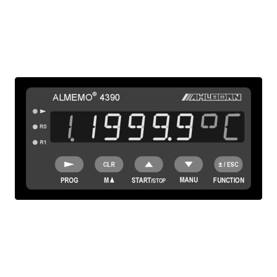
____________________________ Operating instructions English Precision panel meter ALMEMO ® 4390-2 V1.1 23.09.2009 www.ahlborn.com... - Page 2 1. Operating controls 1. OPERATING CONTROLS Front view (1) LED display (a) Measuring point, port (b) Measured value, parameter (c) Units, function (2) Signal lights ► Start measuring Relay R0 active Relay R1 active (3) Operating keys Programming PROG Meas. point selection M ▲...
-
Page 3: Table Of Contents
Contents table 2. CONTENTS TABLE 1. OPERATING CONTROLS................2 3. GENERAL....................6 3.1 Warranty....................6 3.2 Standard delivery................6 3.3 Waste disposal..................7 4. SAFETY PRECAUTIONS................7 4.1 Special notes on use................7 5. INTRODUCTION..................8 5.1 Functions.....................8 5.1.1 Sensor programming..............9 5.1.2 Measuring operation..............10 5.1.3 Process control .................11 6. - Page 4 2. Contents table 10.2.6 Cold junction compensation.............29 10.2.7 Atmospheric pressure compensation ........30 10.2.8 Temperature compensation.............30 10.3 Averaging..................31 10.3.1 Smoothing meas. val. by means of a sliding average ....31 10.3.2 Averaging mode...............32 10.3.3 Averaging over manually set individual meas. operations..32 10.3.4 Averaging over time..............33 10.3.5 Averaging over the cycle............33 10.3.6 Volume flow measurement............34 10.4 Measuring point scans and data output........36...
- Page 5 Contents table 13.1.1 Data cables................51 13.1.2 Analog modules................51 13.2 V6 interface elements..............52 13.2.1 Relays..................52 13.2.2 Analog outputs.................53 13.2.3 Relay trigger analog modules...........53 14. TROUBLE-SHOOTING................54 15. DECLARATION OF CONFORMITY............55 16. APPENDIX....................56 16.1 Technical data ................56 16.2 Product overview ................56 17. Stichwortverzeichnis................57 17.1 Your contact partner...............58 ALMEMO ®...
-
Page 6: General
3. General 3. GENERAL Congratulations on your purchase of this new and innovative ALMEMO ® mea- suring instrument. Thanks to the patented ALMEMO ® connector the device configures itself automatically; its operation should be fairly straightforward. The device can, however, be used with a wide range of sensors and peri- pherals and offers many different special functions. -
Page 7: Waste Disposal
Waste disposal 3.3 Waste disposal This symbol means that the product is subject to the European Union’s segregated waste disposal regulations. This applies both to the product itself and to any accessories marked with the same symbol. Disposal of any such item as unsorted dome- stic waste is strictly forbidden. -
Page 8: Introduction
5. Introduction 5. INTRODUCTION Panel meter ALMEMO ® 4390-2 is a new member in our family of unique mea- suring devices - all equipped with Ahlborn's patented ALMEMO ® connector system. The intelligent ALMEMO ® connector offers decisive advantages when connecting sensors and peripherals because all parameters are stored in an EEPROM located on the connector itself;... -
Page 9: Sensor Programming
Functions 5.1.1 Sensor programming The measuring channels are programmed, completely and automatically, via the ALMEMO connectors on the sensors. However, the user can easily sup- ® plement or modify this programming via the keypad or via the interface. Measuring ranges Appropriate measuring ranges are available for all sensors with a non-linear characteristic, e.g. -
Page 10: Measuring Operation
5. Introduction Limit values and alarm Per measuring channel two limit values can be set (1 maximum and 1 mini- mum). In the event of one of these limit values being exceeded an alarm con- tact is actuated by the internal relays; these can be allocated individually to specific limit values. -
Page 11: Process Control
Functions Maximum and minimum values For each measuring operation the maximum value and minimum value are ac- quired and saved to memory. These values can then be displayed, output, or deleted from memory. 5.1.3 Process control To record the measured values from the connected sensors in digital form measuring point scanning is performed continuously with measured value out- put according to a time-based process control. - Page 12 5. Introduction connector (available as an accessory) files can be read out very quickly via any standard card reader. Output All data logs, measured values, and programming parameters can be output to any peripheral equipment. Using the appropriate interface cables RS232, RS422, USB, and Ethernet interfaces are available.
-
Page 13: Putting Into Service
Putting into service 6. PUTTING INTO SERVICE 1. Connect the power supply at the terminals provided (9); the power supply re- quired will depend on the variant (see rating plate) and be either 90 to 230 VAC mains or 10 to 30 VDC. see 7 2. -
Page 14: Power Supply
7. Power supply 7. POWER SUPPLY Before connecting any equipment to the power supply always ensu- re that the operating voltage is correct; check the rating plate. 7.1 Mains operation The mains power supply, 90 to 230 VAC at 50-60 Hz, must be connected via the screw terminal of socket (9) on the rear of the device. -
Page 15: Connecting The Sensors / Transducers
Connecting the sensors / transducers 8. CONNECTING THE SENSORS / TRANSDUCERS Any ALMEMO ® sensor can be connected at ALMEMO ® input socket M1 (5). Your own sensors with open ends can be clamped directly onto terminal strip(4) or onto an equivalent ALMEMO ®... -
Page 16: Sensor Connected Via Clamp Connector
8. Connecting the sensors / transducers 8.3 Sensor connected via clamp connector A wide variety of passive sensors not powered from the device can be connec- ted to the clamp connector, terminals A, B, C, D. The pin assignment is shown in the Manual. - Page 17 Potential separation The measuring inputs are electrically isolated from the power supply by means of optocouplers. The power supply itself is also electrically isolated up to 50 V by means of the AC/DC module or the DC/DC converter (OA4390-U). The vol- tage at the measuring inputs themselves (between B, C, D and A or - ) must not exceed 12 volts.
-
Page 18: Display And Keypad
9. Display and keypad 9. DISPLAY AND KEYPAD 9.1 Display Panel meter ALMEMO ® 4390 incorporates an 14-segment 8-digit LED display (1). This can display the measured value with measuring channel and units, menu and menu function in normal text, and the programming functions with channel and abbreviation, e.g.: Measured value Menu... -
Page 19: Keypad
Keypad 9.2 Keypad To operate the device a keypad with 5 keys is provided (3). Each of these keys initially has the function indicated below it. Function Normal Entry Programming PROG ► Measured value, measuring point selection M ▲ Start/stop measuring START/STOP ▲... - Page 20 9. Display and keypad Functions Menufunctions Parameter Abbreviation activation Measuring functions menu MEASFCT MaxValue (Hi) ► MAX VALUE 1. 127.3 MH Standard ▼ MinValue (Lo) MIN VALUE 1. 23.4 ML Standard Average value ▼ AVERAGE 1. 13.24 AV Averaging mode > 0 Number of averaged values ▼...
- Page 21 Function selection and function activation Menu DEVICE DEVICE OO.15.OO CY Standard Cycle ► CYCLE Measuring rate 1O CR Standard ▼ CONVRATE Measuring duration Press and hold down FUNCTION ▼ MEASDUR O1.OO.OO MD Measuring time Press and hold down FUNCTION ▼ MEASTIME O1.23.45 MT Time-of-day...
-
Page 22: Data Entry
9. Display and keypad 9.4 Data entry Parameters can be programmed as follows : FUNKTION To select parameters press ▲ ▼ ► To start programming press PROG `O´OOO.O°C The front digit flashes and can now be changed. To increment the digit press ▲... -
Page 23: Measuring Operations
Measuring operations 10. MEASURING OPERATIONS Panel meter ALMEMO ® 4390-2 offers all the possibilities associated with mea- sured data acquisition. 1. Semi-continuous scanning of all active measuring points see 12.2 Display of any selected measuring point Measured value sent to an analog output see 13.2.2 2. -
Page 24: Maximum And Minimum Value Memories
10. Measuring operations 10.1.3 Maximum and minimum value memories From the measured values acquired per measuring point the highest and lo- west values are determined and saved for each. To display these extremes first the desired channel must be set and then, in the menu ´MEASFNCT´, the function ´MAXVALUE´... -
Page 25: Zero-Point Adjustment
Measured value correction and compensation The measured value is displayed, flashing, ´0000´ 1.`OO.OO´CL with abbreviation ´CL´ To set the measured value to zero press ► To cancel this function press ±/ESC If only a ´C´ appears as abbreviation, this means that the measuring point is locked at level 5 or above. -
Page 26: Setpoint Input
10. Measuring operations 10.2.3 Setpoint input If you set up a 2nd calibration value other than the zero-point, you can, by ente- ring the setpoint, correct a measured value, including gain. On ALMEMO for- ® ce transducers an appropriate calibration resistance is automatically activated for the purposes of final value correction. -
Page 27: Sensor Adjustment For Chemical Sensors And Probes
Measured value correction and compensation To select the ´ADJUST´ function press PROG ADJUST ´ADJUST´ is displayed. To perform the ´Adjust´ function press ► The measured value is displayed, flashing, ´0000´ with 1. `O.OO´AJ abbreviation ´AJ´. To perform zero-point adjustment press ►... -
Page 28: Cold Junction Compensation
10. Measuring operations If this is OK, the display shows 1. `7.OO´AJ ´7.00´ with abbreviation ´ ´. To perform adjustment and save again press ► 7.OO The display shows the corrected measured value. 2. Gain adjustment For the purposes of gain adjustment the gain calibration resource must first be set up (as per Table). -
Page 29: Atmospheric Pressure Compensation
Measured value correction and compensation 10.2.7 Atmospheric pressure compensation Some measured variables depend on the ambient atmospheric pressure; large deviations from standard pressure (1013 mbar) may lead to measuring errors. (see 11.7.1 Measuring range list ´with PC´). e.g. error per 100 mbar Compensation range Relative humidity, psychr. -
Page 30: Averaging
10. Measuring operations 10.3 Averaging The average value for a measured value is needed for various applications. z.B. Smoothing a widely fluctuating measured value (e.g. wind, pressure, etc.) Average flow velocity in a ventilation conduit Hourly or daily average values for weather data (temperature, wind, etc.) Also for consumption values (electric current, water, gas, etc.) The average value M of a measured variable is obtained by adding together a series of measured values (M... -
Page 31: Averaging Mode
Averaging 10.3.2 Averaging mode All averaging operations, except when smoothing a measured value, are speci- fied in the ´AVERAGING MODE´ function ´AM´; the average value appears in the ´AVERAGE VALUE´ function ´AV´; the number of averaged values appears in the ´COUNTS´... -
Page 32: Averaging Over Time
10. Measuring operations OOO1 The ´Count´ function displays 5. Repeat step 4 for each measuring point. With the function channels for average value ´M(t)´ and number ´n(t)´, all function values used in averaging can be output via the in- terface or saved. -
Page 33: Volume Flow Measurement
Averaging 1. CYCLAM Set averaging over a cycle see 10.3.2 OO.15.OOCY Program the cycle see 12.1 1. ----AV Select the average value function and clear To start averaging press (LED ´►´ lights up) START/STOP To stop averaging press (LED ´►´ goes out again) START/STOP Read out average value / cycle in the ´Average value´... - Page 34 10. Measuring operations see 10.3.1. The K factor for correcting the flow profile, as factor for the volume flow channel, should be set to 0.8; (see below). Volume flow function channel To show the volume flow data a function channel is required whose reference channel is aligned to the flow measuring point and / or to the appropriate ave- rage value channel M(t).
-
Page 35: Measuring Point Scans And Data Output
Measuring point scans and data output 10.4 Measuring point scans and data output Measuring point scans can be used to acquire and then evaluate data from all active measuring points at particular times (for the purposes e.g. of averaging, outputting to the interface, or saving to memory). A measuring point scan can be initiated at any time-of-day either manually or automatically by a cycle. -
Page 36: Measured Value Memory
10. Measuring operations 10.5 Measured value memory The measured value memory is used to record measured values acquired from all measuring points by once-only or cyclic measuring point scans. see 10.4. You can use either the internal EEPROM data memory or an exter- nal memory connector with MMC. -
Page 37: Memory Functions
Measured value memory suring operation, a new file will be created; and, if no new file name has been programmed, the index in the file name extension will automatically be incre- mented by 1, e.g. ´ALMEMO.002´. Similarly, if the file name now entered already exists, a new file will be created with the same file name prefix but with a new index. -
Page 38: Memory Output
10. Measuring operations mes. For this purpose the start date and time-of-day and the end date and time-of-day must be programmed. If no date has been programmed, the mea- suring operation will be performed every day within the set period. The current time-of-day must have been programmed. -
Page 39: Sensor Programming
Sensor programming 11. SENSOR PROGRAMMING Since on ALMEMO ® devices all sensor programming is stored in the ALME- ® connector itself, the user will not normally need to reprogram each time. Programming will only be necessary in certain circumstances, e.g. to correct sensor errors, to scale your own sensors, or to stipulate certain limit values;... -
Page 40: Limit Values
11. Sensor programming Locking mode function ´LM´ Select see 9.3 Entry OOO5LM see 9.4 ´OF MX EF LM´ In the display, in front of the locking mode, you should see the output function, multiplexer position, and element flags - assuming these have been program- med. -
Page 41: Scaling, Decimal Point Setting
Scaling, decimal point setting 11.5 Scaling, decimal point setting To display the electrical signal of a sensor as measured value in its physical size it is nearly always necessary to perform decimal point shift, zero-point cor- rection, and multiplication by a factor. To perform these steps the functions ´EXPONENT´... -
Page 42: Selecting The Measuring Range
11. Sensor programming If you enter ´ ´ as units the temperature value will be converted au- °F tomatically from degrees Celsius to degrees Fahrenheit. If you set character ´ °C ´ or ´ °F ´ , cold junction compensation will be di- sabled. - Page 43 Selecting the measuring range Sensors / transducers Connector / ca- Measuring range Units Display ble / sensor AUFE Au-FeCr ZA 9000-FS -270.0... +60.0 °C WR26 W5Re-W26Re (C) ZA 9000-SSC 0.0...+2320.0 °C Ntc type N ZA 9000-FS -50.00...+125.00 °C Ntc3 Ntc type N ZA 9040-SS3 0.000...+45.000 °C...
- Page 44 11. Sensor programming Sensors / transducers Connector / ca- Measuring range Units Display ble / sensor H DT * Dew-point temperature FH A646 -25.0... 100.0 °C H VP * Partial vapor pressure FH A646 0.0...1050.0 mbar H En * Enthalpy with PC FH A646 0.0 ...
-
Page 45: Special Meas. Ranges, Linearization, Multi-Point Calibration
Selecting the measuring range 11.7.2 Special meas. ranges, linearization, multi-point calibration Thanks to the new ALMEMO ® special connectors with extra memory for addi- tional data (bigger EEPROM, code E4) the following tasks can now be perfor- med for the first time with great elegance : 1. -
Page 46: Device Programming
12. Device programming 12. DEVICE PROGRAMMING All sensor parameters are saved in the sensor connector; certain other para- meters are stored in the device itself. These include device address, baud rate, language, display contrast, hysteresis, sensor supply voltage, and times and cycles used for process control. -
Page 47: Measuring Time, Measuring Duration, Timer
Measuring rate Continuous measuring point scan If continuous measuring point scanning is set (only possible via the interface), all active measuring channels are scanned equally often at the chosen measu- ring rate, uninterruptedly one after the other; the results can also be output to the interface or saved to memory at the same rate. -
Page 48: Baud Rate, Data Format
12. Device programming ´TIME´ function ´TM´ Select see 9.3 12.34.56TM Entry see 9.4 hh . mm . ss Enter in 6-character format e.g. 12:34:56 ´DATE´ function ´DA´ Select see 9.3 O1.O2.O8DA Entry see 9.4 TT . MM . JJ Enter in 6-character format e.g. 01.Feb.2008 To clear date or time-of-day press keys PROG 12.5 Baud rate, data format... -
Page 49: Language
Device address and networking ce number (factory default setting is usually 00) can be modified as desired by entering the appropriate data as usual. ´DEV-ADDR´ function ´GA´ Select see 9.3 O1DA Entry see 9.4 Example Adresse 01 In network operation consecutive numbers between 01 and 99 should be used;... -
Page 50: Output Modules
13. Output modules 13. OUTPUT MODULES Almost all ALMEMO ® devices have two output sockets A1 and A2; these can output measured values in either analog or digital form. It is also possible to initiate various functions by means of trigger pulses. To cover all possibilities while also keeping the hardware needed to a minimum the necessary interfa- ces have been integrated in our ALMEMO ®... -
Page 51: V6 Interface Elements
V5 output cables put, e.g. recording cable ZA1601-RK. (see Manual 5.1.1) This gives, depending on the analog output, the following output signals : Voltage output -1.2 ... +2.00 V 0.1mV/Digit Voltage output -6.0 ... +10.0 V 0.5mV/Digit Current output 0.0 ...20.0 mA 1µA/Digit Function port ´A2´, mode, type, recording cable ´RK´... -
Page 52: Analog Outputs
13. Output modules 13.2.2 Analog outputs On option OA4390-R02 two configurable analog outputs ´AA´ are available as ports P6 and P7 at socket P0 (7), either 0 to 10 V or 0 to 20 mA. Choose analog type ´10 V´ or ´20 mA´, e.g. at port ´P6 P6.1OV ´, by pressing and holding down the FUNCTION... -
Page 53: Trouble-Shooting
Trouble-shooting 14. TROUBLE-SHOOTING The ALMEMO 4390 measuring instrument can be configured and programmed in ® many versatile ways. It is suitable for connecting a wide variety of different sen- sors, additional measuring instruments, alarm signaling devices, and peripheral equipment. Given these numerous possibilities the device may in certain circum- stances not behave quite as expected. -
Page 54: Declaration Of Conformity
/ or print out a comprehensive ´Function test´ in the device list or terminal operations. 15. DECLARATION OF CONFORMITY Ahlborn Mess- und Regelungstechnik GmbH declares herewith that measuring instrument ALMEMO 4390-2 carries the CE label and complies in full with the ®... -
Page 55: Appendix
Appendix 16. APPENDIX 16.1 Technical data (s. Man. 2.3) Measuring inputs 1 ALMEMO socket suitable for all ALMEMO sensors ® ® 1 screw terminal socket for sensors with open ends Measuring channels 4 channels per socket for double sensors, function channels A/D converter Delta - sigma, 24 bit, electrically isolated, adjustable 1 to 100... -
Page 56: Stichwortverzeichnis
16. Appendix 17. Index AMR-Control 5.1.3 Analog modules 13.1.2 Analog output 11.8 2, 45 Atmospheric pressure compensation 10.2.7 Averaging 10.3 Averaging mode 10.3.2 Averaging ove meas. operations 10.3.3 Averaging over the cycle 10.3.5 Averaging over time 10.3.4 Baud rate 12.5 calibration resistance 10.2.3 Checksum error... - Page 57 Index Locking level 11.2 Locking the sensor 11.2 Max. and min. value memories 10.1.3 MAXIMUM 11.3 Measured value correction 10.2 measured value to zero 10.2.1 measuring duration 12.3 Measuring input Measuring operations Measuring point scans 10.4 Measuring point selection 11.1 Measuring range overshot Measuring ranges 11.7.1...
- Page 58 16. Appendix time constant 10.3.1 timer 12.3 Trouble-shooting two-point adjustment 10.2.5 26f. Volume flow 10.3.6 WIN-Control 5.1.3 Zero-point adjustment 10.2.2 Units, changing 11.6 ALMEMO 4390-2 ®...
-
Page 59: Your Contact Partner
Your contact partner 17.1 Your contact partner ALMEMO ® 4390-2... - Page 60 16. Appendix ALMEMO 4390-2 ®...
Need help?
Do you have a question about the ALMEMO 4390-2 and is the answer not in the manual?
Questions and answers