
Related Manuals for Lochinvar Amicus Aquastore LAAS 8-455-6


Summary of Contents for Lochinvar Amicus Aquastore LAAS 8-455-6
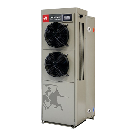
- Page 1 Amicus Aquastore Heat Pump Water Heater Installation, Commissioning, User & Maintenance Instructions Models: LAAS 8-455-6 LAAS 8-455-9 LAAS 8-455-12 LV 336080 | December 2023...
- Page 2 IMPORTANT INFORMATION These instructions must be read and understood before installing, commissioning, operating or maintaining the equipment.
-
Page 3: Preface
Warranty Refer to the appendix Warranty (see 12) for the warranty provisions. Liability User Lochinvar accepts no liability when the water heater is not used correctly and requires the user to: • Read this manual carefully and obey the instructions. - Page 4 See the compliance section. Lochinvar accepts no liability for claims from third parties when: • The instructions for the correct installation of the water heater are not obeyed.
-
Page 5: Compliance
1999, The Water Supply (Water Quality) Regulations (Northern Ireland) 2017 and the Public Water Supplies (Scotland) Amendment Regulations 2017. A kit of parts is available from Lochinvar. Note Manufacturer's notes must not be taken in any way as overriding statutory obligations. -
Page 7: About This Manual
About this manual Scope This manual gives information about safe and correct use of the water heater and how installation, maintenance and service activities have to be done correctly. You must obey the instructions in this manual. Caution Read this manual carefully before you start the water heater. It can cause personal injury and damage to the water heater when you do not read the manual and/or do not obey the instructions. -
Page 8: Document Identification
Caution Obey the caution instructions to prevent damage of the water heater. Warning Obey the warning instructions to prevent danger of personal injury, and serious damage to the water heater. Document identification Article number Language Version 0336080... -
Page 9: Table Of Contents
Table of Contents Preface..................3 Copyright................3 Trademarks............... 3 Warranty................3 Liability................3 Compliance............... 5 Regulations............... 5 Contact information............5 About this manual............... 7 Scope................7 Target group..............7 Notation conventions............7 Document identification............8 User part..............13 Introduction................15 Safety..................17 Interface................... 19 Operator interface............19 3.1.1 Display................19 3.1.2... - Page 10 Turn off the water heater........... 27 4.2.1 Turn off for a short period..........27 4.2.2 Turn off for a long period........... 27 Installation, Maintenance and Service part....29 Introduction................31 About the water heater............. 31 Working principle..............31 Safety..................33 Safety instructions............33 Instructions on the water heater.........34 Safety devices..............36 Environmental aspects............
- Page 11 8.7.1 Filling................47 8.7.2 Turn on the water heater........... 48 Decommissioning............. 48 8.8.1 Turn off the water heater........... 48 8.8.2 Draining................48 Settings..................49 Display................49 Temperatures..............50 9.2.1 Setpoint................50 Modes................51 9.3.1 Mode submenu..............51 Appliance status............... 52 9.4.1 Operating status...............52 Set the time and day............53 9.5.1 Current date..............
- Page 12 Index..................81...
-
Page 13: User Part
User part 0336080_LAAS_EN_V1.3, 04-12-2023... -
Page 15: Introduction
Introduction The LAAS water heater stores and heats water for sanitary purposes. Air from the installation room is forced through an evaporator by two fans (3) and this thermal energy is transfered to the heat exchanger wrapped around the tank via a refrigerant circuit. - Page 16 User part...
-
Page 17: Safety
Safety Lochinvar cannot be held responsible for damages or injuries which can be lead back to: • Failure to follow the instructions provided in this manual. • Carelessness during use or maintenance of the water heater. Every user must study the user part of this manual and must follow the instructions in this part of the manual strictly. - Page 18 The maintenance and refrigerant disposal activities shall be carried out by a qualified service technician. User part...
-
Page 19: Interface
Interface Operator interface The operator interface consists of a (touchscreen) display to navigate through the menu and on which settings, functions, values and errors can be viewed and entered. The display is completely menu-driven and enables the user to change settings and to verify the status and history of the water heater. -
Page 20: Symbols On The Display
3.1.2 Symbols on the display The symbols on the display give visual information about the status of the water heater. Symbol Description There is a heat demand. The water temperature rises. End of water heating (standby). The water temperature drops. The water heater is not able to initiate the heating cycle. -
Page 21: Display Buttons
3.1.3 Display buttons With the buttons on the display, the menu of the water heater can be accessed. Button Function Go to menu [MENU] One step back in menu [BACK] Changed settings will not be saved Save changed settings [ACCEPT] Value up Value down Enter the submenu... -
Page 22: Operating Modes
3.2.1 Operating modes The LAAS has 3 operating modes: • Efficiency mode (see 3.2.1.1) • Hybrid mode (see 3.2.1.2) • Electric mode (see 3.2.1.3) 3.2.1.1 Efficiency mode Efficiency mode is the default, recommended setting. The Efficiency mode is the most energy efficient mode. -
Page 23: Defrost Cycle
3.2.3 Defrost cycle The water heaters covered in this manual are equipped with a Defrost cycle to remove frost and/or ice buildup on the evaporator coil. Factors such as air temperature, humidity, air flow, and the condition of the heat pump system influence when and how often the system will enter into a defrost cycle. - Page 24 User part...
-
Page 25: Use
Turn on the water heater Caution Make sure that the water heater is filled with water before you turn on the water heater. Switch the isolator between the water heater and the mains power supply on to start the water heater. Select one of the 3 operating modes, use the scroll buttons. - Page 26 To change the temperature setpoint: Press [Menu] to access the main menu. Open the Temperatures submenu. User part...
-
Page 27: Turn Off The Water Heater
Open the Setpoint control screen. Change the water temperature setpoint: Use [+] to increase the setpoint. Use [-] to decrease the setpoint. Press [ACCEPT] to confirm the value or press [BACK] to return to the previous screen. Turn off the water heater 4.2.1 Turn off for a short period To turn off the water heater for less than 2 months, set the water heater isolator switch to... - Page 28 User part...
-
Page 29: Installation, Maintenance And Service Part
Installation, Maintenance and Service part 0336080_LAAS_EN_V1.3, 04-12-2023... - Page 30 User part...
-
Page 31: Introduction
Introduction About the water heater The LAAS water heater is intended for heating water for sanitary purpose. The LAAS is a heat pump water heater with two backup elements. The heat pump heats the water and depending on the operation mode the electric elements assist. The heat pump uses air from the room in which it is installed. - Page 32 When the water temperature drops beneath the set temperature, the water heater will be activated and the water is heated. Fig. LAAS water heater 1. Water inlet 2. Heating elements 3. Heat exchanger 4. Water outlet Installation, Maintenance and Service part...
-
Page 33: Safety
Safety Safety instructions For safety instructions on the use of the water heater, refer to Safety (see 2) in the User part of this manual. Warning Installation, maintenance and service must be carried out by a qualified engineer in compliance with the general and local regulations imposed by the water and power supply companies and the fire brigade. -
Page 34: Instructions On The Water Heater
Warning Never install a stop valve or a non-return valve between the expansion vessel/expansion valve and the water heater. Caution The heater is intended to be connected to the water mains permanently. Do not use a hose set to connect the heater. Caution The heat exchanger and compressor of this water heater are filled with R-134a refrigerant. - Page 35 • Some safety pictograms: CE marked UKCA marked Packaging in compliance with ISPM 15 Put the device into a municipal waste collection depot for electrical and electronic equipment (see 6.4.2) Refrigerant R-134a 0336080_LAAS_EN_V1.3, 04-12-2023...
-
Page 36: Safety Devices
Safety devices Fig. Safety thermostat 1. Heating element 2. Safety thermostat - body Safety devices of the water heater: There is a surface-mounted ECO (Energy Cut Out) Safety thermostats control installed for each installed heating element. The ECO high temperature limit switch contacts on each control will open when the tank temperature reaches approximately 93°C. - Page 37 The water heaters covered in this manual are equipped with an Electronic Control system to regulate water temperature inside the storage tank. The control system monitors the temperature from four factory-installed temperature sensors. The operating setpoint is adjusted to regulate water temperature inside the storage tank.
-
Page 38: Environmental Aspects
Environmental aspects 6.4.1 Recycling The packaging material is environmentally friendly, recyclable and relatively easy to discard. 6.4.2 Disposal Old end-of-life appliances contain materials that need to be recycled. When you discard devices at the end of their service life, you must obey local legislation related to waste disposal. -
Page 39: Water Heater
Water heater Structure of the water heater The water heater has the following main components: The water is stored and heated up in the tank. Tank (1) The water is heated by the heating elements. Heating elements (5&8) Heat exchanger (6, 10&11) The water is heated by the heat exchanger Fig. - Page 40 Installation, Maintenance and Service part...
-
Page 41: Installation
This water heater is designed for indoor use only. For more safety instructions, refer to Safety instructions (see 6.1). Packaging Lochinvar recommends to unpack the water heater at or near its intended location. Remove the packaging material carefully to prevent damage to the water heater. Conditions Warning The water heater must be installed on a non-flammable floor and surface. -
Page 42: Water Composition
8.2.3 Water composition The water must comply with the regulations for drinking water for human consumption. Water composition Water hardness > 1.00 mmol/l: German hardness > 5.6° dH French hardness > 10.0° fH English hardness > 7.0° e CaCO > 100 ppm Conductivity >... -
Page 43: Installation Diagram
Installation diagram Fig. Installation diagram 1. Pressure reducing valve (mandatory if the mains water pressure is too high) 3. T&P valve (mandatory) 4. Stop valve (recommended) 5. Non-return valve 6. Circulation pump (optional) 7. Shunt pump 9. Drain valve 11. Service stop valve 12. -
Page 44: Hot Water Connection
8.4.2 Hot water connection Note Insulate long hot water pipes to prevent unnecessary energy loss. Note The use of a T&P valve is mandatory. Install the hot water connection: Install a stop valve (11) in the hot water outlet pipe for service reasons. Install a T&P valve (3). -
Page 45: Preparation
8.5.1 Preparation Remove the top cover and control box cover of the water heater to make the electrical section and the terminal block visible. Remove screws (1) 4x. Warning Live cables inside! Switch off the power supply completely (on local isolator) before opening the top cover to access the electrical components. -
Page 46: Mains Power
The mains power connections have to be connected to the terminal block, refer to Structure of the water heater (see 7.1). Fig. Terminal block 1. Terminal block 2. Cable glands 8.5.2 Mains power Note The water heater is supplied without a power cable and isolator. Use a power cable with wires of a suitable diameter based on the cable length and the current. -
Page 47: Finalization
8.5.3 Finalization When all connections are made, install the control box cover and the top cover on the water heater. Fasten screws (1) 4x. Fig. Install the cover Ventilation The LAAS water heater utilizes ambient air for heating sanitary hot water. It extracts heat from the air, cooling down the room where it is installed in. -
Page 48: Turn On The Water Heater
Open the stop valve (4) of the cold water supply pipe (A). Cold water flows into the water heater. Fill the water heater until a full water jet flows from the nearest draw-off point. The water heater is completely full. Open all draw-off points to bleed the entire installation of air. -
Page 49: Settings
Settings Display The display is completely menu-driven and enables the user to change settings and to verify the status and history of the water heater. For more information about how to use the display, refer to Operator interface (see 3.1). On the display, press [MENU] to enter the main menu. -
Page 50: Temperatures
Temperatures The Temperatures submenu shows the temperature setpoint and the actual temperatures of different levels or positions of the water heater. Fig. Temperature submenu Press on the line with a [>] to set the setpoint. Press [BACK] to return to the previous screen. -
Page 51: Modes
Modes The Mode submenu shows the Mode to select. In this menu, you can change the operating mode: • Efficiency • Hybrid • Electric Fig. Mode submenu 9.3.1 Mode submenu This display emerge by start up of the machine. The machine starts in the Efficiency mode To change the mode: From the Mode submenu open the Mode control screen. -
Page 52: Appliance Status
Appliance status Fig. Appliance status submenu The Appliance Status submenu shows detailed information of the appliance: Current status of the appliance. Status Mode Current mode of the appliance. Upper element On or Off On or Off Lower element On or Off On or Off Compressor Current status of the 4 Way Valve. -
Page 53: Set The Time And Day
Set the time and day The Clock submenu shows the Current time and Current date of the system. Fig. Clock submenu Press on a line with a [>] to set the Date or Time. Press [BACK] to return to the previous screen. -
Page 54: Current Time
9.5.2 Current time To change the time: From the Clock menu open the Current time control screen. Change the setpoint: The [^] indicates which value can be changed. Use [+] to increase the value. Use [-] to decrease the value. Use [>] and [<] to move between days, hours and minutes. -
Page 55: Set The Unit Of Temperature
9.6.1 Set the unit of temperature To change the unit of temperature: From the Display Settings submenu open the Unit of temperature control screen. Change the setting. Press [ACCEPT] to confirm the value or press [BACK] to return to the previous screen. -
Page 56: Set The Backlight Delay
9.6.3 Set the backlight delay If you set the display brightness to 1 or higher, the display becomes brighter when you press a button. The backlight delay sets how long it takes before the backlight switches back to low level. To change the backlight delay: From the Display Settings submenu open the Backlight Delay control screen. -
Page 57: Appliance Information
Appliance information From the Main menu, you can open the Appliance Information submenu. The Appliance Information submenu shows information about the operating history of the water heater. Fig. Display - Appliance Information Total time the appliance has been on Total run time Total time the efficiency mode has been on Efficiency mode on Total time the electric mode has been on... - Page 58 these errors. Press the error to open the information about that specific error. Refer to troubleshooting (see 11). Fig. Display - Error History Fig. Display error information Press [BACK] to return to the previous screen. Installation, Maintenance and Service part...
-
Page 59: Error Occurrence
Error occurrence From the Main menu, you can open the Error Occurrence submenu. The Error Occurrence submenu shows the number of errors for each error category. Fig. Display - Error Occurrence Press [BACK] to return to the previous screen. 0336080_LAAS_EN_V1.3, 04-12-2023... -
Page 60: Restore Default
9.10 Restore default From the Main menu, you can open the Restore Default submenu. On the Restore Default submenu you can restore the settings to the factory default settings. Fig. Display - Restore default Press [Yes] to confirm or [No] to return to the previous screen. Installation, Maintenance and Service part... -
Page 61: Maintenance
The water heater needs maintenance at least once a year. The maintenance interval is determined by the water quality, the average operation hours each day and the set water temperature. To determine the correct interval, Lochinvar recommends to do a system check three months after installation. Note Do maintenance to maintain an effective and efficient transfer of heat to the water. -
Page 62: Descale The Tank
Inspect the volume of the anode. When the anode is consumed for 60 % or more, replace the anode. Note If the anode needs to be replaced, always use an anode of the same type. Please refer to the type and the serial number on the data plate. Place the anode in the water heater. -
Page 63: Performance Check
Remove the lowest heating element: Loosen electrical wires earth (A) and live (L) on the element. Loosen the element (2). Take the element out of the water heater (3). Carefully store the element. Inspect the tank on limescale through the opening. When there is limescale: Use a descaling agent to remove the scale and contamination. -
Page 64: Finalization
Install the service cover. Install the left side plate. If necessary, fill the water heater (see 8.7.1). 10.4 Finalization When all maintenance activities are done: If necessary, fill the water heater (see 8.7.1). Turn on the water heater (see 4.1). Check if the performance of all components is correct: Make sure that the water heater operates the operating cycle correctly. -
Page 65: Troubleshooting
Troubleshooting 11.1 Errors and warnings The water heater can have three different kinds of errors: • General errors, which are not displayed • Displayed errors, which are divided in two different groups: Lock out errors: when the cause is removed, you can reset the error to resume operation. - Page 66 Indication Cause Measure The water heater is off. Turn on the water heater (see 4.1). Insufficient or no hot water The temperature is set too low. Set the setpoint higher. There is no supply voltage. Make sure that: the isolator is in ON position. there is power on the isolator.
-
Page 67: Displayed Errors
11.1.2 Displayed errors Note For the coding of the connections, refer to the Electrical wiring diagram. Note Contact your service and maintenance engineer if the error persists. Note Each error has a code and a description. Description Code Cause Measure Relay Water temperature is sensed to be Recycle electrical power to heater. - Page 68 No communication between main Contact a qualified installer or service Communication control board and UIM. agency for repair. Refer to phone number listed on the technical support label located on the unit. Upper contactor No communication between the Turn off power at the breaker or main control board and upper disconnect switch and check for element contactor and or elements.
-
Page 69: Warranty
Warranty Contact Lochinvar or go to www.lochinvar.ltd.uk for the current warranty terms and conditions. 0336080_LAAS_EN_V1.3, 04-12-2023... - Page 70 Installation, Maintenance and Service part...
- Page 71 Appendices Technical details Description Unit LAAS LAAS LAAS 8-455-6 8-455-9 8-455-12 General Contents Empty weight Filled weight Maximum floor load Maximum operating pressure kPa (bar) 800 (8) 800 (8) 800 (8) Maximum Control temperature (Heat exchanger) °C Maximum Control temperature (Electric) °C Operating setpoint - adjustment range (Heat exchanger) °C...
- Page 72 Description Unit LAAS LAAS LAAS 8-455-6 8-455-9 8-455-12 Heat exchanger Input Power Total airflow over evaporator m³/h 2380 Refrigerant R-134a Chemical name 1,1,1,2 Tetrafluoroethane Refrigerant weight 1,85 GWP value refrigerant 1430 CO² ton equivalent 2,646 COP (warm water) < 3,2 SCOP (warm water) <...
- Page 73 Dimensions Size Description Unit LAAS 8-455-6 LAAS 8-455-9 LAAS 8-455-12 Dimensions water heater Overall height 1770 Appliance diameter Depth Dimensions connections Cold water supply connection (female) " NPT Hot water outlet connection (female) " NPT T&P-valve connection (female) " NPT Drain valve connection (female) "...
- Page 74 Installation, Maintenance and Service part...
- Page 75 Energy labeling Description Unit LAAS LAAS LAAS 8-455-6 8-455-9 8-455-12 Declared load profile Load profile Energy efficiency class (Energy label) Energy efficiency Daily electricity consumption 6,01 6,01 6,01 Annually electricity consumption kWh/year 1272 1272 1272 Daily fuel consumption kWh GCV Annually fuel consumption GJ/year Mixed water 40 °C (according V40)
- Page 76 Electrical wiring diagram Fig. Electrical wiring diagram Installation, Maintenance and Service part...
- Page 77 Cable colors Blue Green Black Orange White Brown Yellow/Green Terminal block connections Earth Phase 1 input Phase 2 input Phase 3 input Components Compressor Capacitor compressor Control Fans 4-Way valve Display Electronic expansion valve Lower pressure switch Refrigerant loop sensors Tank temperature sensors Element (bottom/lower) Element (top/upper)
- Page 78 Declaration of conformity A.5.1 United Kingdom CE Installation, Maintenance and Service part...
- Page 79 A.5.2 United Kingdom UKCA 0336080_LAAS_EN_V1.3, 04-12-2023...
- Page 80 Installation, Maintenance and Service part...
- Page 81 Index About the water heater...... 31 Filling ..........47 About this manual....... 7 Finalization......... 47, 64 Ambient conditions ......41 Appendices........71 Appliance information......57 Appliance status........52 General errors........65 Circulation connection ....... 44 Cold water connection......43 Hot water connection......44 Commissioning........47 Hybrid mode........22 Compliance........
- Page 82 Packaging.........41 Ventilation........47 Performance check......63 Preface..........3 Preparation......... 45, 61 Warranty.......... 69 Water composition......42 Water connections......43 Recycling..........38 Water heater ........39 Regulations ........5 Water-side maintenance..... 61 Restore default......... 60 Working clearances ......42 Working principle ......31 Safety........17, 33 Safety devices........
- Page 83 ICOM Industri l & Commerci l He tin Equipment Associ tion 8 Lombard Way The MXL Centre, Banbury Oxon, OX16 4TJ +44 (0) 1295 269 981 info@lochinvar.ltd.uk Lochinvar Ltd reserves the right to change specifications without prior notice www.lochinvar.ltd.uk...
Need help?
Do you have a question about the Amicus Aquastore LAAS 8-455-6 and is the answer not in the manual?
Questions and answers