
Related Manuals for Supermicro X11OPi


Summary of Contents for Supermicro X11OPi
- Page 1 X11OPi Platform with X11OPi-CPU Board AOM-X11OPi-LBG Card RSC-X11OPi-PCIE Card AOM-X11OPi-HDD Card AOM-X11OPi-KVM Card BPN-X11OPi Midplane USER’S MANUAL Revision 1.2...
- Page 2 State of California, USA. The State of California, County of Santa Clara shall be the exclusive venue for the resolution of any such disputes. Supermicro's total liability for all claims will not exceed the price paid for the hardware product.
- Page 3 RDIMM DDR4 memory of 2933/2666/2400 MHz in 12 slots. 2933 MHz memory is sup- ported by Second Generation Intel® Xeon® Platinum 82XX processors only. 3. Eeach X11OPi-CPU board supports up to 3 TB DCPMM memory of up 2933 MHz in 12 slots. DCPMM memory is supported by Second Generation Intel® Xeon® Platinum 82XX processors only.
- Page 4 Super X11OPi Platform User's Manual Manual organization Chapter 1 describes the features, specifications and performance of the X11OPi system. It also provides detailed information on hardware installation instructions. Chapter 2 describes troubleshooting procedures for video, memory, and system setup stored in the CMOS.
- Page 5 Super Micro Computer, Inc. 980 Rock Ave. San Jose, CA 95131 U.S.A. Tel: +1 (408) 503-8000 Fax: +1 (408) 503-8008 Email: marketing@supermicro.com (General Information) support@supermicro.com (Technical Support) Website: www.supermicro.com Europe Address: Super Micro Computer B.V. Het Sterrenbeeld 28, 5215 ML...
-
Page 6: Table Of Contents
Location of the X11OPi-CPU Board ................13 Major Components on the X11OPi-CPU Board ...............14 Connectors on the X11OPi-CPU ..................14 Processor and Memory Support on the X11OPi-CPU Board ...........15 Installing the Intel® Xeon® Platinum 8XXX Processor ...........16 Overview of the Processor Socket Assembly ..............17 Overview of the Processor Heatsink Module (PHM) ............18... - Page 7 Location of the BPN-X11OPi Midplane ................58 Major Components on the BPN-X11OPi Midplane ............59 Major Components on the Front Side of the BPN-X11OPi Midplane .......60 Major Components on the Rear Side of the BPN-X11OPi Midplane .......61 Major Components on the Reverse Side of the BPN-X11OPi Midplane ......62 1-8 X11OPi Platform Features ....................64...
- Page 8 Super X11OPi Platform User's Manual Chapter 2 Troubleshooting 2-1 Troubleshooting Procedures ....................71 2-2 Technical Support Procedures ...................74 2-3 Battery Removal and Installation ..................75 2-4 Frequently Asked Questions ....................76 2-5 Returning Merchandise for Service ..................78 Chapter 3 UEFI BIOS 3.1 Introduction .........................79 3.2 Main Setup .........................80...
- Page 9 Table of Contents F.3 Secure Boot Settings .......................181 F.4 Key Management Settings ....................184...
-
Page 10: Chapter 1 Introduction
For more information regarding this product, please visit our website at www.supermicro.com. Note: The X11OPi-CPU board is intended to be used in conjunction with the AOM-X11OPi-LBG card, the RSC-X11OPi-PCIE card, the AOM-X11OPi-HDD card, and the BPN-X11OPi midplane as an integrated server platform. -
Page 11: The X11Opi-Cpu Board
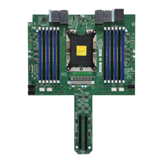
Chapter 1: Introduction 1-2 The X11OPi-CPU Board Your system can support up to eight X11OPi-CPU boards on the front side of the BPN-X11OPi midplane. The following section provides detailed information on the X11OPi-CPU board. X11OPi-CPU Board Image (Rev. 1.00) Note: All graphics shown in this manual were based upon the latest PCB revision avail- able at the time of publishing this manual. - Page 12 Super X11OPi Platform User's Manual X11OPi-CPU Board Layout (not drawn to scale) PWR1 PWR2 X11OPi-CPU JLED1 Rev. 1.00 GPU POWER GPU POWER NVME 2 NVME 3 NVME 1 NVME 0 GPU POWER Note: Components not documented are for internal testing only.
-
Page 13: Location Of The X11Opi-Cpu Board
Chapter 1: Introduction Location of the X11OPi-CPU Board X11OPi-CPU Board BPN-X11OPi Midplane X11OPi-CPU Board One (1) CPU Board on the Front Side of the X11OPi Midplane Eight (8) CPU Boards (max.) on the Front Side of the X11OPi Midplane... -
Page 14: Major Components On The X11Opi-Cpu Board
Super X11OPi Platform User's Manual Major Components on the X11OPi-CPU Board PWR1 PWR2 X11OPi-CPU JLED1 Rev. 1.00 JPWR4 GPU POWER JPWR3 GPU POWER JPWR5 NVME 2 NVME 3 NVME 1 NVME 0 GPU POWER NVME3 NVME2 NVME1 NVME0 Connectors on the X11OPi-CPU... -
Page 15: Processor And Memory Support On The X11Opi-Cpu Board
DIMMB1/B2, Intel® Xeon® Platinum 82XX processors only. DIMMC1/C2, 2. Eeach X11OPi-CPU board supports up to 3 TB DCPMM memory of up 2933 MHz in 12 slots. DCPMM DIMMD1/D2, memory is supported by Second Generation Intel® Xeon® Platinum 82XX processors only. -
Page 16: Installing The Intel® Xeon® Platinum 8Xxx Processor
• Make sure to install the processor and memory into the X11OPi-CPU board before you install the CPU board into the CPU board slot on the front side of the BPN-X11OPi midplane. • When receiving a system without a processor pre-installed, make sure that the plastic CPU socket cap is in place and that none of the socket pins are bent;... -
Page 17: Overview Of The Processor Socket Assembly
Chapter 1: Introduction Overview of the Processor Socket Assembly The processor socket assembly contains 1)Intel® Xeon® Platinum 8XXX processor (Note below), 2) the narrow processor clip, 3) the dust cover, and 4) the CPU socket Note: The Intel® Xeon® Platinum 8XXX processor contains the F model and the non-F model processors. -
Page 18: Overview Of The Processor Heatsink Module (Phm)
Super X11OPi Platform User's Manual Overview of the Processor Heatsink Module (PHM) The Processor Heatsink Module (PHM) contains 1) a heatsink, 2) a narrow processor clip, and 3) the Intel® Xeon® Platinum 8XXX processor. 1. Heatsink 2. Narrow processor clip 3. -
Page 19: Attaching The Intel® Xeon® Platinum 8Xxx Processor To The Narrow Processor Clip To Create The Processor Package Assembly
Chapter 1: Introduction Attaching the Intel® Xeon® Platinum 8XXX Processor to the Narrow Processor Clip to Create the Processor Package Assembly Locate pin 1 (notch A), which is the triangle located on the top of the narrow processor clip. Also locate notch B and notch C on the processor clip. Locate pin 1 (notch A), which is the triangle on the substrate of the CPU. -
Page 20: Attaching The Processor Package Assembly To The Heatsink To Form The Processor Heatsink Module (Phm)
Super X11OPi Platform User's Manual Attaching the Processor Package Assembly to the Heatsink to Form the Processor Heatsink Module (PHM) After you have made a processor package assembly by following the instructions on the previous page, please follow the steps below to mount the processor package assembly onto the heatsink to create the Processor Heatsink Module (PHM). -
Page 21: Preparing The Cpu Socket For Installation
Chapter 1: Introduction Preparing the CPU Socket for Installation This motherboard comes with the CPU socket pre-assembled in the factory. The CPU socket contains 1) a dust cover, 2) a socket bracket, 3) the CPU socket, and 4) a back plate. These components are pre-installed on the motherboard before shipping. -
Page 22: Installing The Processor Heatsink Module (Phm)
Super X11OPi Platform User's Manual Installing the Processor Heatsink Module (PHM) Once you have assembled the processor heatsink module (PHM), you are ready to in- stall the processor heatsink module (PHM) into the CPU socket on the motherboard. To install the PHM into the CPU socket, follow the instructions below. -
Page 23: Removing The Processor Heatsink Module (Phm) From The Motherboard
Chapter 1: Introduction Removing the Processor Heatsink Module (PHM) from the Motherboard Before removing the processor heatsink module (PHM), unplug power cord from the power outlet. Using a T30 Torx-bit screwdriver, turn the screws on the PHM counterclockwise to loos- en them from the socket, starting with screw marked #4 (in the sequence of 4, 3, 2, 1). -
Page 24: Memory Support And Installation
Super X11OPi Platform User's Manual Memory Support and Installation Note: Check the Supermicro website for recommended memory modules. Memory Support Each CPU board supports up to 3 TB DCPMM* or 3DS LRDIMM (Load Reduced)/ LRDIMM/3DS RDIMM (Regiestered)/RDIMM DDR4 memory of 2933*/2666/2400/2133 MHz in 12 DIMM slots. -
Page 25: Ddr4 Memory Support For Intel® Xeon® Platinum 8Xxx Processors
4H-128GB 4H-256GB 2933 2933 Notes: 1. 2933 MHz memory support in two-DIMMs per-channel (2DPC) configuration can be achieved by using memory purchased from Supermicro. 2. 2933 MHz memory is supported by the Second Generation Intel® Xeon® Platinum 82XX processor only. -
Page 26: Dimm Population Guidelines For Optimal Performance
Super X11OPi Platform User's Manual DIMM Population Guidelines for Optimal Performance For optimal memory performance, follow the instructions listed in the tables below when populating memory modules. Key Parameters for DIMM Configuration Key Parameters for DIMM Configurations Parameters Possible Values... - Page 27 Chapter 1: Introduction Memory Population Table DCPMM Population Table (X11OPi+ w/8 CPU Boards & 96 DIMMs Installed) 8 CPU boards & 96 DIMMs Memory Population Sequence (12 DIMMs per CPU board) CPU1: CPU Board 1 + 12 DIMMs P1-DIMMC1/P1-DIMMC2/P1-DIMMB1/P1-DIMMB2/P1-DIMMA1/P1-DIMMA2/ P1-DIMMD2/P1-DIMMD1/P1-DIMME2/P1-DIMME1/P1-DIMMF2/P1-DIMMF1...
- Page 28 Super X11OPi Platform User's Manual Symmetric Population 2-1-1 (For Channel Configuration: 2-1-1) Modes P1-DIMMF1 P1-DIMMF2 P1-DIMME1 P1-DIMME2 P1-DIMMD1 P1-DIMMD2 P1-DIMMA2 P1-DIMMA1 P1-DIMMB2 P1-DIMMB1 P1-DIMMC2 P1-DIMMC1 CPU1 DRAM1 DRAM1 DRAM1 DCPMM DCPMM DRAM1 DRAM1 DRAM1 DCPMM DCPMM DRAM2 DRAM2 DRAM2 DRAM2...
- Page 29 Chapter 1: Introduction Symmetric Population 1-1-1 (For Channel Configuration: 1-1-1) Modes P1-DIMMF1 P1-DIMMF2 P1-DIMME1 P1-DIMME2 P1-DIMMD1 P1-DIMMD2 P1-DIMMA2 P1-DIMMA1 P1-DIMMB2 P1-DIMMB1 P1-DIMMC2 P1-DIMMC1 CPU1 DCPMM DRAM1 DRAM1 DRAM1 DRAM1 DCPMM DCPMM DCPMM DRAM1 DRAM1 DRAM1 DRAM1 AD + MM DCPMM DRAM3 DRAM3 DRAM3...
- Page 30 Super X11OPi Platform User's Manual Validation Matrix (DDR4 DIMMs Validated w/DCPMM) DIMM Capacity (GB) Ranks Per DIMM DIMM Type & Data Width DRAM Density (Stack) 1Rx4 16GB 2Rx8 16GB RDIMM 2Rx4 16GB 32GB LRDIMM 4Rx4 64GB LRDIMM 3DS 8Rx4 (4H)
- Page 31 CAUTION Exercise extreme care when installing or removing DIMM modules to prevent any possible damage. Check Supermicro's website for recommended memory modules. Install the desired number of DIMM modules on the CPU board; each board supports up to 12 DIMMs. When installing memory, be sure to always populate the blue slots first, starting with DIMMA1, DIMMB1, DIMMC1, DIMMD1, DIMME1, and DIMMF1.
-
Page 32: The Aom-X11Opi-Lbg Card
Super X11OPi Platform User's Manual 1-3 The AOM-X11OPi-LBG Card Your system comes with the AOM-X11OPi-LBG card, which is to be installed on the BPN-X11OPi midplane. This section provides the information on the Intel C621 chipset add- on module. AOM-X11OPi-LBG Image... - Page 33 Chapter 1: Introduction AOM-X11OPi-LBG Layout LED1 JUIDB1 IPMI LAN JUSB1 JSIOM1 SIOM:CPU3 PCI-E 3.0 X16 SRW4 SRW8 I-SATA4 AOM-X11OPi-LBG Rev. 1.00 22110 BMC_HB_LED1 I-SATA3 SRW3 SRW7 2280 SRW2 SRW6 2260 BAR CODE SRW5 SRW1 2242 BIOS LICENSE LAN MAC BMC MAC...
-
Page 34: Location Of The Aom-X11Opi-Lbg Card
Super X11OPi Platform User's Manual Location of the AOM-X11OPi-LBG Card AOM-X11OPi-LBG Card AOM-X11OPi-LBG Card on the Reverse side of the Midplane BPN-X11OPi Midplane (Reverse Side) AOM-X11OPi-LBG Card on the Reverse Side of the X11OPi Midplane... -
Page 35: Major Components On The Aom-X11Opi-Lbg Card
Chapter 1: Introduction Major Components on the AOM-X11OPi-LBG Card This section provides detailed information of the major components on the AOM-X11OPi-LBG card. AOM-X11OPi-LBG Layout UID Switch IPMI LAN LED1 UID LED JUIDB1 IPMI LAN Battery (BT1) TPM/Port80 VROC (Intel RAID key) -
Page 36: Quick Reference To The Components On The Aom-X11Opi-Lbg
Power connector DVD ROM power header (optional) JSD1/JSD2 Power Connectors 1/2 for I-SATA DOM (Disk_on_Module) devices (See Note 2 below.) SIOM (Super I/O Module) PCI-E 3.0 x16 slot supported by CPU3 for use of a Supermicro- JSIOM1 proprietary add-on card JTPM1 TPM (Trusted Platform Module)/Port 80 header (See Note 2 below.) -
Page 37: Jumpers And Connectors On The Aom-X11Opi-Lbg
Chapter 1: Introduction Jumpers and Connectors on the AOM-X11OPi-LBG How Jumpers Work To modify the operation of the motherboard, jumpers can be used to choose between optional settings. Jumpers create shorts between two pins to change the function of the connector. - Page 38 Super X11OPi Platform User's Manual Manufacturer Mode Select Close pin 2 and pin 3 of Jumper JPME1 to bypass SPI flash security and force the system to operate in the Manufacturer mode, allowing the user to flash the system firmware from a host server for system-setting modifications.
-
Page 39: Headers And Connectors
DOM storage devices. These modified SATA connectors have two power pins that allow Supermicro supplied DOM devices to operate without any extra power cables. For DOM devices that require external power, two extra two pin headers placed right next to I-SATA ports, are available. - Page 40 Two M.2 connectors (J1/J2) provide support for two M.2 SSD storage modules. These connectors are keyed for PCIe 3.0 x4 and SATA 3.0 connectivity. The X11OPi-LBG board provides mounting holes for three lengths of M2 modules: 2260, 2280 and 22110 standards.
- Page 41 Chapter 1: Introduction Universal Serial Bus (USB) An internal USB header, located at JUSB1, provides two USB 2.0 connections (USB 5/USB6) for your system. In addition, a Type A 3.0 header (JUSB2) also provides USB 3.0 Port 1 and USB 2.0 Port 2 connections for internal access. (Cables are not included). See the tables below for pin definitions.
- Page 42 A Unit Identifier (UID) switch (JUIDB1) and an UID LED ( indicator are located on the AOM-X11OPi-LBG. The UID LED (LED1) is located next to the UID switch. When you press the UID switch, the UID LED will be turned on. Press the UID switch again to turn it off. These UID indicator provide easy identification of a system unit that may be in need of service.
- Page 43 Chapter 1: Introduction IPMI LAN An IPMI_dedicated LAN, located on the AOM-X11OPi-LBG, provides KVM support for IPMI 2.0. This port accepts an RJ45_type cable. IPMI LAN Activity LED (Right) LED State LED Color Status Definition Yellow Blinking Active IPMI LAN LED Indicators The IPMI LAN has two LED indicators.
-
Page 44: Led Indicators
Super X11OPi Platform User's Manual LED Indicators BMC Heartbeat LED A BMC Heartbeat LED is located at BMC_HB_LED1 on the motherboard. When this LED is blinking, BMC functions normally. See the table below for more information. BMC Heartbeat LED Status... -
Page 45: The Rsc-X11Opi-Pcie Card
Chapter 1: Introduction 1-4 The RSC-X11OPi-PCIE Card This section provides the information on the RSC-X11OPi-PCIE add-on card. RSC-X11OPi-PCIE Card Image (Rev. 1.00) RSC-X11OPi-PCIE Card Layout (Front Side) RSC-X11OPi-PCIE BAR CODE Rev. 1.00 SLOT1 PCI-E 3.0 X16 RSC-X11OPi-PCIE Card Layout (Reverse Side) -
Page 46: Location Of The Rsc-X11Opi-Pcie Cards
Location of the RSC-X11OPi-PCIE Cards RSC-X11OPi-PCIE (PCI-E Card) (5 Max.) BPN-X11OPi Midplane (Reverse Side) RSC-X11OPi-PCIE Card on the Reverse Side of the X11OPi Midplane (w/5 PCI-E Cards max.) Five (5) RSC-X11OPi-PCIE on the Rear side of Midplane BPN-X11OPi Midplane (Reverse Side) -
Page 47: Major Components On The Rsc-X11Opi-Pcie Card
Chapter 1: Introduction Major Components on the RSC-X11OPi-PCIE Card RSC-X11OPi-PCIE Card Layout (Front) RSC-X11OPi-PCIE BAR CODE Rev. 1.00 SLOT1 PCI-E 3.0 X16 Slot1 PCI-E 3.0x16 (J2) RSC-X11OPi-PCIE Card Layout (Reverse Side) Hot-Plug Attention SW (SW1) Hot-Plug Attention LED (D1) Major Components on the RSC-X11OPi-PCIE... -
Page 48: The Aom-X11Opi-Hdd Card
Super X11OPi Platform User's Manual 1-5 The AOM-X11OPi-HDD Card This section provides the information on the AOM-X11OPi-HDD add-on card. AOM-X11OPi-HDD Image (Rev. 1.00) AOM-X11OPi-HDD Layout SLOT2 PCI-E 3.0 X8 (IN X16) SLOT1 PCI-E 3.0 X8 (IN X16) AOM-X11OPi-HDD REV:1.00 BAR CODE... -
Page 49: Location Of The Aom-X11Opi-Hdd Card
The AOM-X11OPi-HDD Card The BPN-X11OPi Midplane (Rear Side) Power Supply BPN-X11OPi Midplane (Rear Side) AOM NEW - Ver B Lite The AOM-X11OPi-HDD Card 4-7-2017 The HDD Card & 8 CPU Boards (max.) on the Front Side of the X11OPi Midplane... -
Page 50: Major Components On The Aom-X11Opi-Hdd Card
Super X11OPi Platform User's Manual Major Components on the AOM-X11OPi-HDD Card Slot2 PCI-E 3.0 x8 in x16 (J7) SLOT2 PCI-E 3.0 X8 (IN X16) SLOT1 PCI-E 3.0 X8 (IN X16) AOM-X11OPi-HDD REV:1.00 BAR CODE Slot1 PCI-E 3.0 x8 in x16 (J6) - Page 51 SATA 3.0 Ports Two Serial ATA 3.0 headers (JS1/JS3) support eight SATA 3.0 connections (SATA0-3, 4-7) on the AOM-X11OPi-HDD card. These ports, supported by the Intel C621 Chipset, provide serial-link signal connections, which are faster than the connections of Parallel ATA.
-
Page 52: The Aom-X11Opi-Kvm Card
Super X11OPi Platform User's Manual 1-6 The AOM-X11OPi-KVM Card This section provides the information on the AOM-X11OPi-KVM add-on card. AOM-X11OPi-KVM Card Image (Rev. 1.01) JKVM1 Connector (w/support of Keyboard/Monitor/Mouse/2xUSB) (Rear Side) AOM-X11OPi-KVM Card Layout (Rev. 1.01) (Front Side) JKVM1 Connector (w/support of Keyboard/Monitor/Mouse/2xUSB) AOM-X11OPi-KVM REV:1.01... -
Page 53: Major Components On The Aom-X11Opi-Kvm Card
Your system comes with the AOM-X11OPi-KVM card, which is to be installed on the rear side of the BPN-X11OPi midplane. The JKVM1 connector, located at the end of the AOM-X11OPi-KVM card, provides connections for a keyboard, an external VGA monitor (from BMC), a serial COM port, and two USB 2.0 ports. -
Page 54: Major Components On The Aom-X11Opi-Kvm Card
Note: For your I/O and communication devices to work properly, please use the SMCI proprietary cable(CBL-0218L) to connect the JKVM1 connector on the AOM-X11OPi-KVM carde to your keyboard, mouse, VGA monitor, com (serial) port and (two) USB 2.0 devices as shown below. -
Page 55: Bpn-X11Opi Midplane
Chapter 1: Introduction 1-7 BPN-X11OPi Midplane This section provides detailed information on the BPN-X11OPi midplane. BPN-X11OPi Midplane Image (Front Side) BPN-X11OPi Midplane Image (Reverse Side) - Page 56 Super X11OPi Platform User's Manual BPN-X11OPi Midplane Layout (Front Side) BPN-X11OPi Rev.1.00 CUT OFF CUT OFF CUT OFF CUT OFF CUT OFF CUT OFF CUT OFF JG17 JG10 JG12 JG14 JG16 JG11 JG15 JG13 BPN-X11OPi Midplane Layout (Rear Side) HPSXB2: PCIE SLOT1 CPU4 PCI-E 3.0 X16...
-
Page 57: Front View Of The Bpn-X11Opi Midplane
Chapter 1: Introduction Front View of the BPN-X11OPi Midplane Rear View of the BPN-X11OPi Midplane... -
Page 58: Location Of The Bpn-X11Opi Midplane
Super X11OPi Platform User's Manual Location of the BPN-X11OPi Midplane BPN-X11OPi Midplane (Front Side) The HDD Card The CPU Board The BPN-X11OPi Midplane (Front Side) BPN-X11OPi Midplane (Rear Side) The BPN-X11OPi Midplane (Rear Side) Power Supply AOM NEW - Ver B Lite... -
Page 59: Major Components On The Bpn-X11Opi Midplane
The following section provides detailed information of the major components on the front side of the BPN-X11OPi midplane. Please note that all CPU boards and HDD card are installed on the front side of the midplane, and can be accessed from the front side of your system. -
Page 60: Major Components On The Front Side Of The Bpn-X11Opi Midplane
CPU Board slot used for X11OPi-CPU Board 8 FCP (Front Control Panel ) Front Control Panel header HPSXB1 (CPU2Slot1) 2 x PCI-E 3.0 x8 slot supported by CPU2 (for the AOM-X11OPi-HDD card) JPWR1/JPWR2 Power connectors 1/2 for X11OPi-CPU Board 1... -
Page 61: Major Components On The Rear Side Of The Bpn-X11Opi Midplane
The following section provides the information of the major components on the reverse side of the BPN-X11OPi midplane. Please note that the PCH card, PCI-E card, power supply modules, and cooling fans are installed on the reverse side of the midplane, and can be accessed from the rear side of your system. -
Page 62: Major Components On The Reverse Side Of The Bpn-X11Opi Midplane
Super X11OPi Platform User's Manual Major Components on the Reverse Side of the BPN-X11OPi Midplane Major Components on the Reverse Side of the BPN-X11OPi Item# Location Detailed Description J51/J52/J54/J55/J56 PCH Board Slot (SIOM) CPU1/CPU3 PCI-E 3.0 x16 Slot (for the AOM-X11OPi-LBG) HPSXB2: Slot1 CPU4 PCI-E 3.0 x 16... - Page 63 Chapter 1: Introduction Fan Headers There are 16 system/CPU fan headers (Fans 1-8_1) on reverse side of the BPN-X11OPi midplane. All these 4-pin fans headers are backward-compatible with the traditional 3-pin fans. However, fan speed control is available for 4-pin fans only by Thermal Management via the IPMI 2.0 interface.
-
Page 64: X11Opi Platform Features
It also supports up to 4.5 TB DCPMM & DDR4 combined memory of up to 2933 MHz in 12 slots per CPU board. With eight X11OPi-CPU boards built-in, the X11OPi Platform provides up to 24 TB of DCPMM/DDR4 memory or up to 36 TB of DCPMM &... - Page 65 • Sixteen (16) power connectors on the reverse side of the BPN-X11OPi midplane for cooling fan use • Five (5) main system power supplies (PSU1-PSU5) on the reverse side of the BPN-X11OPi midplane for system use • ACPI/ACPM Power Management •...
- Page 66 Super X11OPi Platform User's Manual X11OPi System Block Diagram UPI 10.4GT/s CPU3 PCIE X16, X16, X16 CPU7 PCIE X16, X16, X16 CPU1 PCIE X16, X16, X16 CPU6 PCIE X16, X16, X16 CPU1 DMI3 (X4) DDR4/DCPMM CH.A DDR4/DCPMM CH.A DDR4/DCPMM CH.A DDR4/DCPMM CH.A...
-
Page 67: Processor And Chipset Overview
Chapter 1: Introduction 1.9 Processor and Chipset Overview Built upon the functionality and capability of the Intel® Xeon® Platinum 8XXX (Socket P) processors with support of Intel C621 chipset (Note 1 below), this platform provides superb system performance, efficient power management, and a rich feature set based on cutting- edge technologies to address the needs of next-generation users. -
Page 68: Special Features
The default setting is Last State. 1-11 System Health Monitoring This section describes the health monitoring features of the X11OPi Platform. The system has an onboard Baseboard Management Controller (BMC) that supports system health monitoring. -
Page 69: Acpi Features
These power connectors include the following: • Two (2) 8-pin power connectors (PWR1/2) used for CPU power (on the BPN-X11OPi mid- plane) and three (3) 8-pin power connectors (JPWR3/4/5) used for GPU power on each X11OPi-CPU board (w/8 CPU boards maximum), •... -
Page 70: Advanced Power Management
Super X11OPi Platform User's Manual Warning! To avoid damaging the power supply or the system, be sure to connect all the power connectors mentioned above to the power supplies. Failure to do so will void the manufacturer warranties on both your power supply and your system. -
Page 71: Chapter 2 Troubleshooting
4. Disconnect all cables from the system board, including those for the keyboard and mouse. 5. Remove all I/O modules and add-on cards. 6. Install the X11OPi-CPU cards on the BPN-X11OPi midplane first (-making sure the CPU is fully seated), and connect the front panel connectors to the system board. No Power 1. - Page 72 RAM speed of DIMMs are used in the system. 3. Make sure that you are using the correct type of memory modules as recommended by Supermicro. Please refer to the memory support section on the CPU board section in Chapter 1.
- Page 73 3. HDD support: Check whether all hard disk drives (HDDs) work properly. Replace the bad HDDs with good ones. (HDDs are on the AOM-X11OPi-HDD card.) 4. System cooling: Check system cooling to make sure that all heatsink fans, and CPU/ system fans, etc., work properly.
-
Page 74: Technical Support Procedures
(FAQ) sections in this chapter or see the FAQs on our website (http://www.supermicro. com/) before contacting Technical Support. 2. BIOS upgrades can be downloaded from our website (http://www.supermicro.com). 3. If you still cannot resolve the problem, include the following information when contacting Supermicro for technical support: •... -
Page 75: Battery Removal And Installation
Chapter 2: Troubleshooting 2-3 Battery Removal and Installation Battery Removal (Located on the AOM-X11OPi-LBG card) To remove the onboard battery, follow the steps below: 1. Power off your system and unplug your power cable. 2. Locate the onboard battery as shown below. -
Page 76: Frequently Asked Questions
2-4 Frequently Asked Questions Question: What type of memory does my system support? Answer: The X11OPi supports up to 3 TB DCPMM or 3DS LRDIMM/LRDIMM/3DS RDIMM/ RDIMM DDR4 memory of 2933*/2666/2400 MHz in 12 memory modules per CPU board. It also supports up to 4.5 TB of DCPMM &... - Page 77 Chapter 2: Troubleshooting Question: How do I update my BIOS under UEFI Shell? Note: We do not recommend that you update your BIOS if you are not experiencing a BIOS-related problem. If you need to update your BIOS, please follow the steps below to properly update your BIOS under UEFI Shell.
-
Page 78: Returning Merchandise For Service
Super X11OPi Platform User's Manual 2-5 Returning Merchandise for Service A receipt or copy of your invoice marked with the date of purchase is required before any warranty service will be rendered. You can obtain service by calling your vendor for a Returned Merchandise Authorization (RMA) number. -
Page 79: Chapter 3 Uefi Bios
UEFI BIOS 3.1 Introduction This chapter describes the AMIBIOS™ setup utility for the X11OPi Platform motherboard. The BIOS is stored on a chip and can be easily upgraded using a flash program. Note: Due to periodic changes to the BIOS, some settings may have been added or deleted and might not yet be recorded in this manual. -
Page 80: Main Setup
Super X11OPi Platform User's Manual 3.2 Main Setup When you first enter the AMI BIOS setup utility, you will see the Main setup screen. You can always return to the Main setup screen by selecting the Main tab on the top of the screen. - Page 81 Chapter 3: UEFI BIOS Memory Information Total Memory This feature displays the total size of memory available in the system. Memory Speed This feature displays the default speed of the memory modules installed in the system.
-
Page 82: Advanced Setup Configurations
Super X11OPi Platform User's Manual 3.3 Advanced Setup Configurations Use the arrow keys to select the Advanced submenu and press <Enter> to access the submenu items: Warning: Take Caution when changing the Advanced settings. An incorrect value, an improper DRAM frequency, or a wrong BIOS timing setting may cause the system to malfunction. When this occurs, restore the setting to the manufacturer default setting. - Page 83 Chapter 3: UEFI BIOS Wait For 'F1' If Error Select Enabled to force the system to wait until the <F1> key is pressed if an error occurs. The options are Disabled and Enabled. Interrupt 19 Capture Interrupt 19 is the software interrupt that handles the boot disk function. When this feature is set to Immediate, the ROM BIOS of the host adaptors will "capture"...
- Page 84 Super X11OPi Platform User's Manual CPU Configuration Warning: Setting the wrong values in the following sections may cause the system to malfunc- tion. Processor Configuration The following CPU information will display: • Processor BSP Revision • Processor Socket •...
- Page 85 Chapter 3: UEFI BIOS Intel Virtualization Technology (Available when two or more processors are installed on the motherboard) Select Enable to use Intel Virtualization Technology which will allow multiple workloads to share the same set of common resources. On shared virtualized hardware, various workloads (or tasks) can co-exist, sharing the same resources, while functioning in full independence from each other, and migrating freely across multi-level infrastructures and scale as needed.
- Page 86 Super X11OPi Platform User's Manual Force x2APIC (Extended Advanced Programmable Interrupt Controller) Select Enable to force the BIOS to use the x2 APIC mode which will allow the operating system to perform more efficiently on high-core CPU configurations and optimize interrupt distribution in virtualization.
- Page 87 Chapter 3: UEFI BIOS CPU P State Control (Available when "Power Technology" is set to Custom) SpeedStep (PStates) EIST (Enhanced Intel SpeedStep Technology) allows the system to automatically adjust processor voltage and core frequency in an effort to reduce power consumption and heat dissipation.
- Page 88 Super X11OPi Platform User's Manual CPU C6 Report (Available when Autonomous Core C-State is set to Disable) Select Enable to allow the BIOS to report the CPU C6 state (ACPI C3) to the operating system. During the CPU C6 state, power to all caches is turned off. The options are Auto, Enable, and Disable.
- Page 89 Chapter 3: UEFI BIOS • UPI Global MMIO Low Base/Limit • UPI Global MMIO High Base/Limit • UPI PCI-E Configuration Base/Size Degrade Precedence Use this feature to select the degrading precedence option for Ultra Path Interconnect (UPI) connections. Select Topology Precedent to degrade UPI features if system options are in conflict.
- Page 90 Super X11OPi Platform User's Manual Stale AtoS (A to S) The in-memory directory has three states: I, A, and S states. The I (-invalid) state indicates that the data is clean and does not exist in the cache of any other sockets. The A (-snoop All) state indicates that the data may exist in another socket in an exclusive or modified state.
- Page 91 Chapter 3: UEFI BIOS Memory Frequency Use this feature to set the maximum memory frequency for onboard memory modules. The options are Auto, 1866, 2000, 2133, 2400, 2666, and 2933. (Note: 2933 MHz memory is supported by the Second Generation Intel® Xeon® Platinum 82XX processor only.) Data Scrambling for DDR4 Select Enable to enable data scrambling for DDR4 memory to enhance system performance and security.
- Page 92 Super X11OPi Platform User's Manual Reset Trigger ADR (Async DIMM Self-Refresh) Upon system power loss, an ADR sequence will be triggered to allow ADR to flush the write-protected data buffers in the memory controller and place the DRAM memory in self- refresh mode.
- Page 93 Chapter 3: UEFI BIOS • P7 DIMMA1/DIMMA2/DIMMB1/DIMMB2/DIMMC1/DIMMC2/DIMMD1/DIMMD2/ DIMME1/DIMME2/DIMMF1/DIMMF2 • P8 DIMMA1/DIMMA2/DIMMB1/DIMMB2/DIMMC1/DIMMC2/DIMMD1/DIMMD2/ DIMME1/DIMME2/DIMMF1/DIMMF2 Memory Map Use this submenu to configure the following Memory Map settings. Volatile Memory Mode Select 1LM to use 1LM memory mode for volatile memory modules installed in the system. Select 2LM to use 2LM memory mode for volatile memory modules installed in the system.
- Page 94 Super X11OPi Platform User's Manual Memory RAS (Reliability_Availability_Serviceability) Configuration Use this submenu to configure the following Memory RAS settings. Static Virtual Lockstep Mode Select Enable to support Static Virtual Lockstep mode to enhance memory performance. The options are Enable and Disable.
- Page 95 Chapter 3: UEFI BIOS from issuing a performance penalty before a device fails. Please note that virtual lockstep mode will only start to work for ADDDC after a faulty DRAM module is spared. The options are Disable and Enable. Patrol Scrub Patrol Scrubbing is a process that allows the CPU to correct correctable memory errors detected in a memory module and send the corrections to the requestor (the original source).
- Page 96 Super X11OPi Platform User's Manual Socket 1 PCI-E Br0D00F0 - Port 0/DMI (Available for Socket 1 Configuration) Link Speed Use this feature to configure the link speed of a PCI-E port specified by the user. The options are Auto, Gen 1 (Generation 1) (2.5 GT/s), Gen 2 (Generation 2) (5 GT/s), and...
- Page 97 Chapter 3: UEFI BIOS Relaxed Ordering Select Enable to allow certain transactions to be processed and completed before other transactions that have already been enqueued. The options are Disable and Enable. Intel VT for Directed I/O (VT-d) Intel® VT for Directed I/O (VT-d) Select Enable to use Intel Virtualization Technology support for Direct I/O VT-d by reporting the I/O device assignments to the VMM (Virtual Machine Monitor) through the DMAR ACPI tables.
- Page 98 Super X11OPi Platform User's Manual Intel® VMD Technology Use this feature to configure Intel Volume Management Device (VMD) Technology settings. Note: After you’ve enabled VMD in the BIOS on a backplane (BPN) of your choice, this backplane will be dedicated for VMD use only, and it will no longer support any PCI-E device.
- Page 99 Chapter 3: UEFI BIOS Port 60/64 Emulation Select Enabled for I/O port 60h/64h emulation support, which in turn, will provide complete legacy USB keyboard support for the operating systems that do not support legacy USB devices. The options are Enabled and Disabled. PCIe PLL SSC Select Enabled for PCH PCI-E Spread Spectrum Clocking support, which will allow the BIOS to monitor and attempt to reduce the level of Electromagnetic Interference caused by the...
- Page 100 Super X11OPi Platform User's Manual Configure SATA as (Available when SATA Controller is set to Enable) Select AHCI to configure a SATA drive specified by the user as an AHCI drive. Select RAID to configure a SATA drive specified by the user as a RAID drive. The options are AHCI and RAID.
- Page 101 Chapter 3: UEFI BIOS sSATA Configuration When this submenu is selected, the AMI BIOS automatically detects the presence of the sSATA devices that are supported by the sSATA controller and displays the following items: sSATA Controller This feature enables or disables the onboard sSATA controller supported by Intel PCH. The options are Enable and Disable.
- Page 102 Super X11OPi Platform User's Manual sSATA Device Type Use this feature to specify if the device installed on the sSATA port specified by the user should be connected to a Solid State drive or a Hard Disk Drive. The options are Hard Disk Drive and Solid State Drive.
- Page 103 Chapter 3: UEFI BIOS Onboard Devices Option ROM Setting Use this feature to configure the Option ROM setting for an onboard device specified by the user to be used for system boot. Onboard Video OPROM (Option ROM) Use this feature to set the type of the onboard video device specified by the user for system boot.
- Page 104 Super X11OPi Platform User's Manual Ipv4 HTTP Support Select Enabled to enable Ipv4 HTTP boot support. If this feature is disabled, it will not create the Ipv4 HTTP boot option. The options are Enabled and Disabled. Ipv6 PXE Support Select Enabled to enable Ipv6 PXE boot support. If this feature is disabled, it will not create the Ipv6 PXE boot option.
- Page 105 Chapter 3: UEFI BIOS The options for Serial Port 1 are Auto, (IO=3F8h; IRQ=4), (IO=3F8h; IRQ=3, 4, 5, 6, 7, 9, 10, 11, 12), (IO=2F8h; IRQ=3, 4, 5, 6, 7, 9, 10, 11, 12); (IO=3E8h; IRQ=3, 4, 5, 6, 7, 9, 10, 11, 12), and (IO=2E8h;...
- Page 106 Super X11OPi Platform User's Manual Bits Per second Use this feature to set the transmission speed for a serial port used in Console Redirection. Make sure that the same speed is used in the host computer and the client computer. A lower transmission speed may be required for long and busy lines.
- Page 107 Chapter 3: UEFI BIOS COM2/SOL (Serial-Over-LAN) Console Redirection (for SOL/COM2) Select Enabled to use the SOL port for Console Redirection. The options are Enabled and Disabled. *If the item above is set to Enabled, the following items will become available for user's configuration: Console Redirection Settings (for SOL/COM2) ...
- Page 108 Super X11OPi Platform User's Manual Flow Control Use this feature to set the flow control for Console Redirection to prevent data loss caused by buffer overflow. Send a "Stop" signal to stop sending data when the receiving buffer is full. Send a "Start" signal to start data-sending when the receiving buffer is empty. The options are None and Hardware RTS/CTS.
- Page 109 Chapter 3: UEFI BIOS Serial Port for Out-of-Band Management/Windows Emergency Management Services (EMS) The feature allows the user to configure Console Redirection settings to support Out-of- Band Serial Port management. Console Redirection (for EMS) Select Enabled to use a COM port specified by the user for EMS Console Redirection. The options are Disabled and Enabled.
- Page 110 Super X11OPi Platform User's Manual ACPI Settings Use this feature to configure Advanced Configuration and Power Interface (ACPI) power management settings for your system. NUMA Support (Available when the OS supports this feature) Select Enabled to enable Non-Uniform Memory Access support to enhance system perfor- mance.
- Page 111 Chapter 3: UEFI BIOS Security Device Support If this feature and the TPM jumper (JPT1) on the motherboard are both enabled, the onboard security (TPM) device will be enabled in the BIOS to enhance data integrity and system security. Please note that the OS will not show the security device. Neither TCG EFI protocol nor INT1A interaction will be made available for use.
- Page 112 Super X11OPi Platform User's Manual Endorsement Hierarchy Select Enabled for Endorsement Hierarchy support, which contains separate controls to address the user's privacy concerns because the primary keys in this hierarchy are certified by the TPM or the manufacturer to be used as an authentic TPM device attached to an authentic platform.
- Page 113 Chapter 3: UEFI BIOS Cert (Certification) GUID (Global Unique Identifier) This feature displays the GUID for this system. Commit Changes and Exit Select this feature to keep the changes you have made and exit from the system. Discard Changes and Exit ...
- Page 114 Super X11OPi Platform User's Manual RAM Disk Configuration This feature allows the user to configure the settings for the RAM disks installed in the system. When you select this submenu and press <Enter>, the following items will display: Disk Memory •...
- Page 115 Chapter 3: UEFI BIOS Intel® Optane® DC Persistent Memory Configuration When you select this submenu and press <Enter>, the following screen will display: • Version: This feature displays the version of DCPMM used in the system. • Select an action below •...
- Page 116 Super X11OPi Platform User's Manual • DIMM Physical ID: This feature displays the physical ID of the DCPMM module. • Manageability State: This feature indicates the manageability state of the DCPMM module. • Health State: This feature indicates the health state of the DCPMM module.
- Page 117 Chapter 3: UEFI BIOS • Interface Format Code • Manufacturing Information Valid • Manufacturing Date • Manufacturing Location • Memory Type • Memory Bank Label • Data Width Label [b] • Total Width [b] • Speed [MHz] • Channel ID •...
- Page 118 Super X11OPi Platform User's Manual • Package Sparing Enabled • Package Spares Available • Configuration Status • SKU Violation • ARS Status • Overwrite DIMM Status • Last Shutdown Time • First Fast Refresh • Viral Policy Enable • Viral State •...
- Page 119 Chapter 3: UEFI BIOS Monitor Health Select this submenu to view the health status and thresholds of the DCPMM module specified by the user. • Sensor Type: This feature displays the type of health items that are being monitored. •...
- Page 120 Super X11OPi Platform User's Manual • File: This feature allows the user to specify the file path in the root directory that contains the new firmware for firmware update. • Staged Firmware Version: This feature indicates the staged firmware version of the DCPMM module specified by the user.
- Page 121 Chapter 3: UEFI BIOS Enable First Fast Fresh State Select Enabled to support the first fast fresh state of DCPMM data policy. Disable First Fast Fresh State Select Disable to disable the first fast fresh state of DCPMM data policy. Back to Main Menu ...
- Page 122 Super X11OPi Platform User's Manual Regions Current Configuration Region ID 1/Region ID 2/Region ID 3 When this submenu is selected, the following items will display: • Region ID: This feature displays the Region ID of the DCPMM module.
- Page 123 Chapter 3: UEFI BIOS Namespace Label Version Use this feature to view and modify the namespace label version to initialize when creating goals. The options are 1.2 and 1.1. Back to Regions Menu Select this feature and press <Enter> to go back to the Regions submenu. Back to Main Menu ...
- Page 124 Super X11OPi Platform User's Manual Delete After configuring the settings for the namespace above, click on <delete> to delete the changes you've made on the namespace. Please note that all data contained in the namespace will be deleted as well when you press <delete>.
- Page 125 Chapter 3: UEFI BIOS • App. Direct Capacity: This feature specifies the App. direct capacity of the DCPMM module. • Memory Capacity: This feature specifies the memory capacity of the DCPMM module. • Unconfigured Capacity: This feature specifies the capacity of the DCPMM module that has not been configured.
- Page 126 Super X11OPi Platform User's Manual Execute Tests Select this feature and press <Enter> to execute the selected diagnostic tests. The following items will display: • TestName • State • Message Back to Main Menu Select this feature and press <Enter> to go back to the Intel® Optane® DC Persistent Memory Configuration menu.
-
Page 127: Event Logs
Chapter 3: UEFI BIOS 3.4 Event Logs Use this feature to configure Event Log settings. Note: After you've made a change on a setting below, please be sure to reboot the system for the change to take effect. Change SMBIOS Event Log Settings Enabling/Disabling Options SMBIOS Event Log Select Enabled to enable SMBIOS (System Management BIOS) Event Logging during system... - Page 128 Super X11OPi Platform User's Manual SMBIOS Event Log Standard Settings Log System Boot Event Select Enabled to log system boot events. The options are Enabled and Disabled. MECI (Multiple Event Count Increment) Enter the increment value for the multiple event counter. Enter a number between 1 to 255.
-
Page 129: Ipmi
Chapter 3: UEFI BIOS 3.5 IPMI Use this feature to configure Intelligent Platform Management Interface (IPMI) settings. When you select this submenu and press the <Enter> key, the following information will display: • IPMI Firmware Revision: This feature indicates the IPMI firmware revision used in your system. - Page 130 Super X11OPi Platform User's Manual When SEL is Full This feature allows the user to determine what the BIOS should do when the system event log is full. Select Erase Immediately to erase all events in the log when the system event log is full.
- Page 131 Chapter 3: UEFI BIOS IPMI LAN Selection (Available when Update IPMI LAN Configuration is set to Yes) Use this feature to select the type of the IPMI LAN. The options are Dedicated, Shared, and Failover. VLAN Select Enabled to enable IPMI VLAN function support. The options are Disabled and Enabled.
-
Page 132: Security Settings
Super X11OPi Platform User's Manual 3.6 Security Settings This menu allows the user to configure the following security settings for the system. Administrator Password Use this feature to set the administrator password which is required to enter the BIOS setup utility. - Page 133 Chapter 3: UEFI BIOS Secure Boot When you select this submenu and press the <Enter> key, the following items will display: • System Mode Secure Boot Select Enabled to use Secure Boot settings. The options are Enabled and Disabled. Secure Boot Mode Use this feature to select the desired secure boot mode for the system.
- Page 134 Super X11OPi Platform User's Manual Export Secure Boot Variables This feature is used to copy the NVRAM content of Secure Boot variables to a storage device. Enroll EFI Image Select this feature and press <Enter> to specify an EFI (Extensible Firmware Interface) image for the system to use when it operates in the Secure Boot mode.
- Page 135 Chapter 3: UEFI BIOS Forbidden Signatures This feature allows the user to enter and configure a set of values to be used as Forbidden Signatures for the system. These values also indicate sizes, keys numbers, and key sources of the forbidden signatures. Select Update to update your "Forbidden Signatures". Select Append to append your "Forbidden Signatures".
-
Page 136: Boot Settings
Super X11OPi Platform User's Manual 3.7 Boot Settings Use this feature to configure Boot Settings: Fast Boot Select Enabled to support fast boot by initializing a minimal set of devices that are required to boot up the system. The options are Enabled and Disabled. - Page 137 Chapter 3: UEFI BIOS When the item above -"Boot Mode Select" is set to UEFI, the following items will be displayed for configuration: • Boot Option #1 - Boot Option #9 Add New Boot Option This feature allows the user to add a new boot option to the boot priority features for system boot.
- Page 138 Super X11OPi Platform User's Manual Create After the driver option name and the file path are set, press <Enter> to enter to submenu and click OK to create the new boot option drive. Delete Driver Option Use this item to select a boot driver to delete from the boot priority list.
-
Page 139: Save & Exit
Chapter 3: UEFI BIOS 3.8 Save & Exit Select the Save & Exit menu from the BIOS setup screen to configure the settings below. Save Options Discard Changes and Exit Select this option to exit from the BIOS setup utility without making any permanent changes to the system configuration and reboot the computer. - Page 140 Super X11OPi Platform User's Manual Default Options Restore Optimized Defaults To set this feature, select Restore Defaults from the Exit menu and press <Enter> to load manufacturer default settings which are intended for maximum system performance but not for maximum stability.
-
Page 141: Appendix A Bios Post Codes
Fatal errors are those which will not allow the system to continue the boot up. If a fatal error occurs, you should consult with your system manufacturer to best solutions. Additional BIOS POST Codes The AMI BIOS supplies additional checkpoint codes, which are documented online at http:// www.supermicro.com/support/manuals/ ("AMI BIOS POST Codes User's Guide"). -
Page 142: Appendix B Software
USB/SATA DVD drive, or a USB flash drive, or the IPMI KVM console. 2. Retrieve the proper RST/RSTe driver. Go to the Supermicro web page for your motherboard and click on "Download the Latest Drivers and Utilities", select the proper driver, and copy it to a USB flash drive. - Page 143 Appendix B: Software 4. During Windows Setup, continue to the dialog where you select the drives on which to install Windows. If the disk you want to use is not listed, click on “Load driver” link at the bottom left corner. To load the driver, browse the USB flash drive for the proper driver files.
-
Page 144: Driver Installation
The Supermicro website contains drivers and utilities for your system at https://www. supermicro.com/wftp/driver. Some of these must be installed, such as the chipset driver. After accessing the website, go into the CDR_Images (in the parent directory of the above link) and locate the ISO file for your motherboard. Download this file to a USB flash drive or a DVD. -
Page 145: Superdoctor ® 5
B.3 SuperDoctor ® The Supermicro SuperDoctor 5 is a program that functions in a command-line or web-based interface for Windows and Linux operating systems. The program monitors such system health information as CPU temperature, system voltages, system power consumption, fan speed, and provides alerts via email or Simple Network Management Protocol (SNMP). -
Page 146: Ipmi
When logging in to the BMC for the first time, please use the unique password provided by Supermicro to log in. You can change the unique password to a user name and password of your choice for subsequent logins. -
Page 147: Appendix C Standardized Warning Statements
The following statements are industry standard warnings, provided to warn the user of a situation when possible bodily injury may occur. Should you have questions or experience difficulty, contact Supermicro's Technical Support department for assistance. Only certified technicians should attempt to install or configure components. - Page 148 Super X11OPi Platform User's Manual Attention Danger d'explosion si la pile n'est pas remplacée correctement. Ne la remplacer que par une pile de type semblable ou équivalent, recommandée par le fabricant. Jeter les piles usagées conformément aux instructions du fabricant.
- Page 149 Appendix C: Standardized Warning Statements Product Disposal Warning! Ultimate disposal of this product should be handled according to all national laws and regulations. 製品の廃棄 この製品を廃棄処分する場合、 国の関係する全ての法律 ・ 条例に従い処理する必要があります。 警告 本产品的废弃处理应根据所有国家的法律和规章进行。 警告 本產品的廢棄處理應根據所有國家的法律和規章進行。 Warnung Die Entsorgung dieses Produkts sollte gemäß allen Bestimmungen und Gesetzen des Landes erfolgen.
-
Page 150: Appendix D Uefi Bios Recovery
Warning: Do not upgrade the BIOS unless your system has a BIOS-related issue. Flashing the wrong BIOS can cause irreparable damage to the system. In no event shall Supermicro be liable for direct, indirect, special, incidental, or consequential damages arising from a BIOS update. -
Page 151: Recovering The Main Bios Block With A Usb Device
1. Please use a different machine to download the BIOS package for your motherboard or your system from the product page available on our website at www.supermicro.com. 2. Extract the BIOS package to a USB device and rename the BIOS ROM file [BIOSname#.###] that is included in the BIOS package to SUPER.ROM for BIOS... - Page 152 Super X11OPi Platform User's Manual 5. After locating the SUPER.ROM file, the system will enter the BIOS Recovery menu as shown below. Note: At this point, you may decide if you want to start the BIOS recovery. If you decide to proceed with BIOS recovery, follow the procedures below.
- Page 153 Appendix D: UEFI BIOS Recovery 7. After the BIOS recovery process is complete, press any key to reboot the system. Note: It is recommended that you update your BIOS after BIOS recovery. Please refer to Chapter 3 for BIOS update instructions. 8.
- Page 154 Super X11OPi Platform User's Manual 9. When the UEFI Shell prompt appears, type fs# to change the device directory path. Go to the directory that contains the BIOS package you extracted earlier from Step 1. Enter flash.nsh BIOSname#.### at the prompt to start the BIOS update process.
-
Page 155: Appendix E Configuring Vroc Raid Settings
RAID settings. The E.3 section describes the use of journaling drive for the RAID5 volume (parity based RAID). Note 1: Only use NVMe devices that have been validated by Supermicro. For the lat- est updates, please contact us or refer to our website at https://www.supermicro.com. - Page 156 Super X11OPi Platform User's Manual 6. When the following screen displays, use the down arrow key to select Intel® VMD Technology and press <Enter> to enter the Intel® VMD Technology submenu. 7. When the Intel® VMD Technology submenu appears, it will display all the PCI slots that can be configured for VMD support on the screen.
- Page 157 Appendix E: Configuring VROC RAID Settings 13. Navigate to the Advanced tab. 14. Use the arrow keys to select Intel(R) Virtual RAID on CPU and press <Enter> to access the menu items. The following screen will appear showing that the feature "All Intel VMD Controllers"...
- Page 158 Super X11OPi Platform User's Manual 15. Use the arrow keys to select All Intel VMD Controllers and press <Enter> to access the menu items. The following screen will appear. It allows the user to create RAID volumes and configure settings of NVMe devices as detected by the system.
-
Page 159: Configuring Raid Settings
Appendix E: Configuring VROC RAID Settings E.2 Configuring RAID Settings Follow the instructions stated in the E.1 section to access the All Intel VMD Controllers menu items, the following screen will appear. Please carefully follow the instructions listed in this section to configure RAID settings for your devices as desired. To Create a RAID Volume Use the arrow keys to select Create RAID Volume from the screen above and press <Enter>... - Page 160 Super X11OPi Platform User's Manual To Enter a Name for the RAID Volume From the Create RAID Volume submenu as shown on the previous screen, use the arrow keys to select Name and press <Enter>, and the following screen will display.
- Page 161 Appendix E: Configuring VROC RAID Settings To Set the RAID Level for the RAID Volume From the Create RAID Volume submenu, select RAID Level and press <Enter>. The following screen will display. Use the arrow keys to select the desired RAID level for the RAID volume that you've created. The options are RAID0(Stripe), RAID1(Mirror), RAID5(Parity), and RAID10(RAID0+1).
- Page 162 Super X11OPi Platform User's Manual Enabling RAID Spanned over VMD Controllers From the Create RAID Volume submenu, use the arrow keys to select Enter RAID spanned over VMD Controllers and press <Enter>. The following screen will display. Enter a desired setting for your RAID volume in the pop-up menu. The options are (not selected) and X (selected).
- Page 163 Appendix E: Configuring VROC RAID Settings To Select Disks for the RAID Volumes From the Create RAID Volume submenu, use the arrow keys to highlight Select Disk: and press <Enter>. The following screen will display. The options are (not selected) and X (selected). Set the features one by one to X to select the desired RAID disks for your RAID volumes.
- Page 164 Super X11OPi Platform User's Manual To Set Strip Size for the RAID Volume From the Create RAID Volume submenu, use the arrow keys to select Strip Size: and press <Enter>. The following screen will display. From the pop-up menu as shown above, select the desired RAID strip size for your RAID volume and press <Enter>.
- Page 165 Appendix E: Configuring VROC RAID Settings To Set the Capacity (GB) for the RAID Volume From the Create RAID Volume submenu, use the arrow keys to select Capacity (GB): and press <Enter>. The following screen will display. Enter the desired RAID capacity (in GB) in the pop-up menu to set the capacity for your RAID volume.
- Page 166 Super X11OPi Platform User's Manual To Create Volumes To finalize your RAID volume configuration, select Create Volume from the Create RAID Volume submenu as shown on the screen below. After selecting Create Volume, press <Enter>. The following screen will appear and...
- Page 167 Appendix E: Configuring VROC RAID Settings To Display RAID Volumes For detailed RAID volume information, use the arrow keys to select the desired RAID volume as shown below. To Display RAID VOLUME Information When the screen above appears, press <Enter>. The RAID VOLUME INFO menu will appear and display the detailed information about the RAID volume you've selected as shown below.
- Page 168 Super X11OPi Platform User's Manual To Delete a RAID Volume On the RAID VOLUME INFO menu, use the arrow keys to select Delete and press <Enter> to delete the RAID volume you have selected. The following screen will appear to confirm if you want to delete the RAID Volume. Select...
- Page 169 Appendix E: Configuring VROC RAID Settings To Reset the RAID Volume to non-RAID On the RAID VOLUME INFO submenu shown on the bottom screen of page 167, select the desired NVMe device from the list of RAID Member Disks and press <Enter> as shown below. Select Reset to Non-RAID from the screen below and press <Enter>...
- Page 170 Super X11OPi Platform User's Manual To Turn on the Disk Locator LED Follow the instructions stated in the E.1 section to access the All Intel VMD Controllers menu. When the following screen displays, select a non-RAID physical disk to turn on the disk locator LED to locate a selected device.
- Page 171 Appendix E: Configuring VROC RAID Settings To Mark a RAID Volume as Spare Follow the instructions stated in the E.1 section to access the All Intel VMD Controllers menu. When the following screen appears, select a desired NVMe device from the list of Non-RAID Physical Disks.
- Page 172 Super X11OPi Platform User's Manual When the following screen appears, select Yes to confirm that you want the selected device to be used as a spare device. The options are Yes and No. Note: A spare disk is used for automatic RAID volume rebuilds when status of failed, missing, or at risk is detected on the array disk.
- Page 173 Appendix E: Configuring VROC RAID Settings To Mark a RAID Volume as a Journaling Drive Refer to the instructions stated in the E.1 section to access the All Intel VMD Controllers menu. When the following screen appears, select a desired NVMe device from the list of Non-RAID Physical Disks for use as a journaling drive.
- Page 174 Super X11OPi Platform User's Manual When the following screen appears, select Yes to confirm that the selected device is to be used as a journaling drive. The options are Yes and No. Note: RAID Write Hole (RWH) is a condition associated with a power/drive-failure/crash while writing to a RAID5 volume.
-
Page 175: Use Of Journaling Drive
Appendix E: Configuring VROC RAID Settings E.3 Use of Journaling Drive The following section describes the use of a journaling drive for the RAID5 volume, which is a parity-based RAID. Step 1. Refer to the instructions stated in the E.1 section to access All Intel VMD Controllers menu items. - Page 176 Super X11OPi Platform User's Manual RWH Policy Press <Enter> and the following screen will appear. If any device has been set as a journaling drive (see pages 173 and 170), the options are Distributed PPL, Journaling Drive, and Disable. If no device has been set as a journaling drive, the options are Distributed PPL and Disable.
- Page 177 Appendix E: Configuring VROC RAID Settings Step 3. Set the feature, RWH Policy, to Journaling Drive. Press <Enter> and the RWH JD feature will become available as shown below. RWH JD Use the arrow keys to select RWH JD. Press <Enter> and the following screen will appear. The feature displays the information of journaling drive(s).
- Page 178 Super X11OPi Platform User's Manual Step 4. Use the arrow keys and press <Enter> to select the desired journaling drive from the option list of RWH JD. Step 5. For the changes to take effect, use the arrow keys to select Change RWH settings and press <Enter>.
-
Page 179: Appendix F Secure Boot Settings
Appendix F: Secure Boot Settings Appendix F Secure Boot Settings Secure boot is a feature of UEFI (Unified Extensible Firmware Interface) that ensures boot loaders are digitally signed and validated. The F.1, F.2, and F.3 sections provide instructions on how to enable the secure boot features. The F.4 section states Key Management settings. F.1 Boot mode select Feature Press <Del>... -
Page 180: Secure Boot/ Secure Boot Mode/ Csm Support Features
Super X11OPi Platform User's Manual F.2 Secure Boot/ Secure Boot Mode/ CSM Support Features Press <Del> during system boot to enter the BIOS Setup utility. Navigate to the Security tab as shown below. Use the arrow keys to select Secure Boot and press <Enter> to access the menu items. The following screen will appear. - Page 181 Appendix F: Secure Boot Settings F.3 Secure Boot Settings To have the secure boot support, be sure to follow the steps below (Step 1 ~ Step 4). Step 1. Set Secure Boot Mode to Standard. Press Yes to install factory default keys as needed. Note: The Key Management menu will become unavailable when Secure Boot Mode is set to Standard.
- Page 182 Super X11OPi Platform User's Manual Step 2. For the changes to take effect, press <F4> to save the settings and exit the BIOS Setup utility. Step 3. Press <Del> during system boot to enter the BIOS Setup utility. Navigate to the Security tab and enter the Secure Boot menu.
- Page 183 Appendix F: Secure Boot Settings Step 4. Press <Del> during system boot to enter the BIOS Setup utility. Navigate to the Security tab and enter the Secure Boot menu. Set Secure Boot to Enabled. For the changes to take effect, press <F4> to save the settings and exit the BIOS Setup utility. Press <Del>...
- Page 184 Super X11OPi Platform User's Manual F.4 Key Management Settings The Key Management menu as shown below, which is available when Secure Boot Mode is set to Custom, allows the secure boot keys to be installed via the external device and be involved in the secure boot process.
- Page 185 Appendix F: Secure Boot Settings Restore Factory Keys Select and press Yes to restore factory default secure boot keys and key variables. Also, it will reset the system to the User mode. The options are Yes and No. Reset To Setup Mode (available when the System Mode is in User ...
- Page 186 Super X11OPi Platform User's Manual Export Secure Boot variables Use this feature to export NVRAM content of secure boot variables to files in a root folder on a file system device. Enroll Efi Image This feature is to enroll SHA256 hash of the binary into the Authorized Signature Data-...
- Page 187 Appendix F: Secure Boot Settings Remove 'UEFI CA' from DB (available when the system is not in Device Guard Ready) Select and press Yes to remove Microsoft UEFI CA certificate from the DB. The options are Yes and No. ...
- Page 188 Super X11OPi Platform User's Manual *Refer to the following settings for keys and signatures related to secure boot. Platform Key (PK) The Platform Key (PK), which is pre-installed in firmware during manufacturing, provides full control of the secure boot key hierarchy. The options are Details, Export, Update, and Delete.
- Page 189 Appendix F: Secure Boot Settings Export: Use the arrow keys to select Export. It is to save the current PKs to a FAT for- matted USB flash drive. Press <Enter> and the following screen will appear. Note: Refer to the right panel of the screen for the file formats accepted.
- Page 190 Super X11OPi Platform User's Manual Update: Use the arrow keys to select Update. It is to load the factory defaults or load PKs from a file on the external device. Press <Enter> and the following screen will appear.
- Page 191 Appendix F: Secure Boot Settings To load the factory defaults, navigate to Yes and press <Enter>. The following screen will appear. To load PKs from a file on the external device, navigate to No and press <Enter>.
- Page 192 Super X11OPi Platform User's Manual When the following screen appears, select the USB flash drive that contains the desired file.
- Page 193 Appendix F: Secure Boot Settings Press <Enter> and the following screen will appear. Delete: Use the arrow keys to select Delete and press <Enter> to clear the current PKs and reset the system to the Setup mode.
- Page 194 Super X11OPi Platform User's Manual Key Exchange Key The Key Exchange Key (KEK), which is held by the operating system vendor, can be updated by the holder of the PK and be used by secure boot to protect access to signa- tures databases.
- Page 195 Appendix F: Secure Boot Settings Press <Enter> and the following screen will appear. To load the factory defaults, navigate to Yes and press <Enter>. The following screen will appear. To load KEKs from a file on the external device, navigate to No and press <Enter>. Refer to pages 192 and 193 on how to load KEKs from a file on the external device.
- Page 196 Super X11OPi Platform User's Manual Delete: Use the arrow keys to select Delete and press <Enter>. Navigate to Yes and press <Enter> to clear the current KEKs. Navigate to No and press <Enter> to delete only one certificate from the key database.
- Page 197 Appendix F: Secure Boot Settings Authorized Signatures Authorized Signature Database (DB) contains authorized signing certificates and digital signatures. The options are Details, Export, Update, Append, and Delete. Select Details to display detailed information of Authorized Signatures. Select Export to save the cur- rent DB to a FAT formatted USB flash drive.
- Page 198 Super X11OPi Platform User's Manual Forbidden Signatures Forbidden Signature Database (DBX), which is the inverse of DB, contains forbidden certificates and digital signatures. The options are Details, Export, Update, Append, and Delete. Select Details to display detailed information of Forbidden Signatures. Select Export to save the current DBX to a FAT formatted USB flash drive.
- Page 199 Appendix F: Secure Boot Settings Authorized TimeStamps Authorized Timestamp Database (DBT) is used to issue and check signed time stamp certificates. The options are Details, Export, Update, Append, and Delete. Select Details to display detailed information of Authorized Timestamps. Select Export to save the cur- rent DBT to a FAT formatted USB flash drive.
- Page 200 Super X11OPi Platform User's Manual OsRecovery Signatures OsRecovery Signatures Database (DBR) contains secure boot authorized recovery vari- ables. The options are Details, Export, Update, Append, and Delete. Select Details to display detailed information of OsRecovery Signatures. Select Export to save the current DBR to a FAT formatted USB flash drive.
Need help?
Do you have a question about the X11OPi and is the answer not in the manual?
Questions and answers