urmet domus 1760/18 Installation Handbook
Hands-free wifi
Hide thumbs
Also See for 1760/18:
- Configuration booklet (148 pages) ,
- User booklet (64 pages) ,
- Installation handbook (40 pages)
Advertisement
Available languages
Available languages
Quick Links
Mod.
1760
DS1760-047C
LBT21228
VIDEO DOOR PHONE 2VOICE HANDS-FREE WiFi
MONITEUR 2VOICE MAIN-LIBRES WiFi
VIDEOINTERFONO 2VOICE MANOS LIBRES WiFi
Interactive Links
LINKLINKLINKLINK
Sch./Ref. 1760/18
(white / blanc / blanco)
Sch./Ref. 1760/19
(black / noire / negro)
INSTALLATION HANDBOOK
NOTICE D'INSTALLATION
MANUAL DE INSTALACIÓN
Advertisement
Chapters

Related Manuals for urmet domus 1760/18


Summary of Contents for urmet domus 1760/18
- Page 1 LBT21228 VIDEO DOOR PHONE 2VOICE HANDS-FREE WiFi MONITEUR 2VOICE MAIN-LIBRES WiFi VIDEOINTERFONO 2VOICE MANOS LIBRES WiFi Interactive Links LINKLINKLINKLINK Sch./Ref. 1760/18 (white / blanc / blanco) Sch./Ref. 1760/19 (black / noire / negro) INSTALLATION HANDBOOK NOTICE D’INSTALLATION MANUAL DE INSTALACIÓN...
-
Page 2: Table Of Contents
Interactive Links The document contains INTERACTIVE LINKS for faster and more efficient consultation. ENGLISH INDEX 1. DESCRIPTION ............................3 2. DESCRIPTION OF COMPONENTS AND FEATURES ................3 INSTALLATION............................5 3.1. TERMINAL DESCRIPTION ....................... 6 3.2. JUMPER AND DIP-SWITCH SW1 NO.1 (DEFAULT) ................ -
Page 3: Description
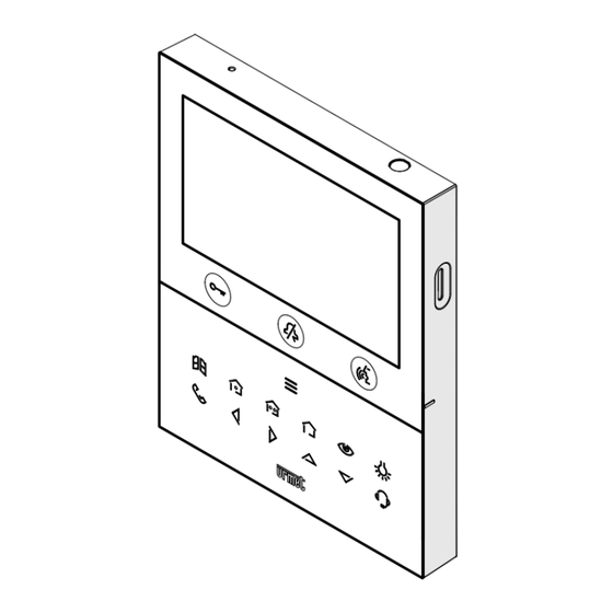
DESCRIPTION The video door phones Ref. 1760/18 and Ref. 1760/19 are dedicated to use in 2Voice video door phone systems. The main features are: • 5’’ (Wide Angle) TFT-LCD colour screen; • backlit soft-touch buttons (*); • possibility of activating video door phone functions via gesture commands on the IR detector or via vocal commands (disabled by default);... - Page 4 : intercom call key : left scrolling arrow key : right scrolling arrow key : upwards scrolling arrow key : downwards scrolling arrow key : switchboard call key Key for activation of secondary functions / display turning on (with green backlighting LED) Raised notches for vision-impaired Pedestrian door opener button (with green / red backlighting LED)
-
Page 5: Installation
INSTALLATION ATTENTION! For proper operation of the Gesture commands, do not install the device in places where it may be exposed to direct sunlight, as the IR detector is sensitive to light. • Install the flush-mounting box Mod. 503 or the flush-mounting box Ø 60 at the height indicated in the following drawing. The flush-mounting box Mod. 503 can be horizontally or vertically installed. • Fix the bracket to the mounting box as indicated. -
Page 6: Terminal Description
3.1. TERMINAL DESCRIPTION Left terminal board Terminals for local power supply unit Ref. 1760/110 Negative for additional chime Positive for additional chime Button Button Right terminal board Floor call PANIC Panic alarm LINE OUT Power supply BUS output LINE IN Power supply BUS input 3.2. -
Page 7: Video Door Phone Performance According To Configuration Method
JUMPER (JP3) The following Jumper allows to adjust the line termination (Z) in case of in-out video door phone connection. The line termination must be inserted into the last video door phone. Termination inserted (default) Termination not inserted For position of jumpers JP1 and JP2 and dip-switch SW1 no.1 refer to the next chapter of the following handbook. -
Page 8: Video Door Phone Installation Constraints
2Voice Ref. 1083/94 CAT5 UTP (one twisted pair) 2Voice Ref. 1083/92 - /94 1083/23 CAT5 UTP (one twisted pair) ATTENTION! Any additional Slave video door phones Ref. 1760/18 - /19 must be powered with the local power supply unit and configured in Local power mode. DS1760-047C... -
Page 9: Contact Insertion For Intercom Calls
DS1760-026” on the Urmet website by scanning the following QR Code. If the video door phone Ref. 1760/18 or /19 is installed as a spare to replace a video door phone, it must be powered through the local power supply and configured with the local power mode of use. 6. CONTACT INSERTION FOR INTERCOM CALLS In order to make intercom calls, it is necessary to enter contacts in the video door phone directory. - Page 10 • The display shows the following screen: • In the configuration menu press the key until selecting “Contacts”. • Press the key to confirm the selection. • To enter an new contact, press the key and select the icon to add a new contact • Press the key to confirm and display the following screen: DS1760-047C...
- Page 11 • The following parameters must be defined for each new contact: Contact type Press the key to select the following icon , then press the key to change the contact type. • External contact: call to a video door phone in another apartment but within the same video door phone riser •...
-
Page 12: Reset To Factory Settings
• Finally, press the key to quit the contact insertion page, the display shows the following screen page: • Press the key to save the contact in the book. Press the key to cancel and return to the contact page. 7. - Page 13 • The display shows the following screen: until selecting “Restore to factory data”. • In the configuration menu press the key • Press the key to confirm the selection. • The display shows the following screen: Press the keys to select which video door phone parameters you want to reset to factory values.
-
Page 14: Technical Specifications
The display shows the following screen page: Press the key to confirm reset to factory data. Press the key to cancel and return to the previous page. TECHNICAL SPECIFICATIONS Power voltage (LINE IN): ........................36 ÷ 48 V Power voltage (V+; V-): ..........................24 V~ Consumption (LINE IN): ........................@ 48 V Stand-by: ............................ -
Page 15: Français
FRANÇAIS SOMMAIRE 1. DESCRIPTION GÉNÉRALE ........................16 2. DESCRIPTION DES COMPOSANTS ET CARACTÉRISTIQUES ............. 16 INSTALLATION............................18 3.1. DESCRIPTION DES BORNES ......................19 3.2. CAVALIER ET COMMUTATEUR DIP SW1 N.1 (DÉFAUT) .............. 19 4. PERFORMANCES DU MONITEUR SELON LE MODE DE CONFIGURATION ........ -
Page 16: Description Générale
DESCRIPTION GÉNÉRALE Les moniteurs Réf. 1760/18 et Réf. 1760/19 sont dédié à l’utilisation du système 2Voice dans les systèmes de portiers vidéo. Principales caractéristiques : • écran couleur TFT-LCD de 5’’ (grand angle) ; • boutons tactiles rétro-éclairé (*); •... - Page 17 : touche activation automatique / renvoi vidéo : touche fonction spéciale : touche appel intercommunicant : touche flèche défilement à gauche : touche flèche défilement à droite : touche flèche défilement en haut : touche flèche défilement en bas : touche appel à la centrale Touche d’activation des fonctions secondaires / allumage de l’écran (avec LED verte d’éclairage de fond) Encoches en relief malvoyants Bouton ouvre-porte piétons (avec LED verte / rouge de rétro-éclairage)
-
Page 18: Installation
INSTALLATION ATTENTION ! Pour un fonctionnement correct des commandes gestuelles (Gesture), ne pas installer le dispositif dans des endroits où il pourrait être exposé aux rayons directs du soleil, car le capteur IR est sensible à la lumière. • Emmurer le boîtier d’encastrement Mod. 503 ou le boîtier d’encastrement Ø 60 à la hauteur indiquée sur le dessin ci-après. -
Page 19: Description Des Bornes
3.1. DESCRIPTION DES BORNES BORNIER GAUCHE Bornes pour alimentateur local Réf. 1760/110 Négative pour sonnerie supplémentaire Positive pour sonnerie supplémentaire Bouton Bouton Bornier droit Appel a l’étage PANIC Alarme de panique LINE OUT Sortie BUS d’alimentation LINE IN Entrée BUS d’alimentation 3.2. -
Page 20: Performances Du Moniteur Selon Le Mode De Configuration
Le cavalier suivant permet le réglage de la terminaison de ligne (Z) en cas de connexion du moniteur en mode entrée-sortie. La terminaison de ligne doit être insérée sur le dernier moniteur. Terminaison insérée (défaut) Terminaison non insérée Le cavalier suivant permet le réglage de la terminaison de ligne (Z) en cas de connexion du moniteur en mode entrée-sortie. -
Page 21: Obligations D'installation Du Moniteur
2Voice Réf. 1083/92 1083/20A 2Voice Réf. 1083/94 CAT5 UTP (une paire torsadée) 2Voice Réf. 1083/92 - /94 1083/23 CAT5 UTP (une paire torsadée) ATTENTION ! Tout moniteur supplémentaire Esclave Réf. 1760/18 - /19 doit être alimenté par l’alimentateur local et configuré selon le mode Confort . DS1760-047C... -
Page 22: Insertion Des Contacts Pour Appels Intercommunicants
DS1760-026 » sur le site Urmet en scannant le QR Code suivant. Si le moniteur Réf. 1760/18 ou / 19 est installé en réserve pour remplacer un autre moniteur, il doit être alimenté via l’alimentation locale et configuré avec le mode d’utilisation Confort. 6. INSERTION DES CONTACTS POUR APPELS INTERCOMMUNICANTS Afin d’effectuer des appels intercommunicants, il faut saisir les contacts dans le répertoire du vidéophone. - Page 23 • L’écran visualise la page-écran suivante : jusqu’à la sélection de l’option « Contacts ». • Dans le menu de configuration, appuyer sur la touche • Appuyer sur la touche pour confirmer la sélection. • Pour insérer un nouveau contact, appuyer sur la touche et sélectionner l’icône d’ajout d’un nouveau contact •...
- Page 24 • Les paramètres suivants doivent être définis pour chaque nouveau contact : Typologie de contact Appuyer sur la touche pour sélectionner l’icône suivante , ensuite appuyer sur la touche pour modifier la typologie de contact. • Contact externe : appel à un moniteur installé dans un autre appartement mais à l’intérieur de la même colonne de vidéophonie •...
-
Page 25: Rétablissement Aux Paramètres D'usine
• Enfin, appuyer sur la touche pour quitter la page d’insertion des contacts, l’écran visualise la page-écran suivante : • Appuyer sur la touche pour enregistrer le contact dans le répertoire. Appuyer sur la touche pour annuler et revenir à la page des contacts. 7. - Page 26 • L’écran visualise la page-écran suivante : jusqu’à la sélection de l’option « Rétablissement • Dans le menu de configuration, appuyer sur la aux données d’usine ». • Appuyer sur la touche pour confirmer la sélection. • L’écran visualise la page-écran suivante : En appuyant sur les touches il est possible de sélectionner les paramètres du moniteur que l’on souhaite rétablir aux valeurs d’usine.
-
Page 27: Caractéristiques Techniques
L’écran visualisera la page-écran suivante : Appuyer sur la touche pour confirmer le rétablissement aux données d’usine. Appuyer sur la touche pour annuler et revenir à la page précédente. CARACTÉRISTIQUES TECHNIQUES Tension d’alimentation (LINE IN): ....................36 ÷ 48 V Tension d’alimentation (V+; V-): ......................24 V~ Consommation Maximum (LINE IN): .................... -
Page 28: Español
ESPAÑOL ÍNDICE 1. DESCRIPCIÓN ............................29 2. DESCRIPCIÓN DE LOS COMPONENTES Y CARACTERÍSTICAS ............29 3. INSTALACIÓN ............................31 3.1. DESCRIPCIÓN DE LOS BORNES ....................32 3.2. JUMPER E INTERRUPTOR SW1 N.1 (DEFAULT) ................32 4. FUNCIONES DEL VIDEOINTERFONO SOBRE LA BASE DE LA MODALIDAD DE CONFIGURACIÓN ... -
Page 29: Descripción
DESCRIPCIÓN Los videointerfonos Ref. 1760/18 y Ref. 1760/19 han sido diseñados para el uso en sistemas de videointerfono 2Voice. Las características principales son: The main features are: • pantalla en color TFT-LCD de 5’’ (Wide Angle); • pulsadores sensibles al tacto iluminados en la cara posterior (*);... - Page 30 : tecla autoencendido / transferencia vídeo : tecla función especial : tecla llamada intercomunicante : tecla flecha desplazamiento hacia la izquierda : tecla flecha desplazamiento hacia la derecha : tecla flecha desplazamiento hacia arriba : tecla flecha desplazamiento hacia abajo : tecla llamada a la central Tecla para la activación de las funciones secundarias / encendido de la pantalla (con led verde de etroiluminación) Muescas en relieve por usuarios ciegos Pulsador de apertura de la puerta para peatones...
-
Page 31: Instalación
INSTALACIÓN ¡ATENCIÓN! Para un funcionamiento correcto de los mandos gestuales (Gesture), no instalar el dispositivo en lugares donde quede expuesto directamente a los rayos solares, ya que el sensor IR es sensible a la luz. • Fijar a la pared la caja empotrada mod. 503 o la caja empotrada Ø 60 a la altura indicada en el dibujo siguiente. La caja empotrada Mod. 503 se puede instalar tanto horizontal como verticalmente. • Fijar el soporte en la caja para empotrar o en la pared, según se indica. -
Page 32: Descripción De Los Bornes
3.1. DESCRIPCIÓN DE LOS BORNES Regleta de bornes izquierda Bornes para alimentador local Ref. 1760/110 Negativo para timbre adicional Positivo para timbre adicional Pulsador Pulsador Regleta de bornes derecha Llamada al piso PANIC Alarma pánico LINE OUT Salida BUS alimentación LINE IN Entrada BUS alimentación 3.2. -
Page 33: Funciones Del Videointerfono Sobre La Base De La Modalidad De Configuración
JUMPER (JP3) El siguiente Jumper permite el ajuste de la terminación de línea (Z) en caso de conexión del videointerfonos entrar-salir. La terminación de línea debe instalarse en el último videointerfonos. Terminación conectada (default) Terminación desconectada Con relación a la posición de los jumper JP1 y JP2 y del interruptor dip SW1 n.1 consultar el siguiente capítulo en el manual. -
Page 34: Limitaciones De Instalación Del Videointerfono
2Voice Ref. 1083/92 - /94 1083/23 CAT5 UTP (un par enredado) ¡ATENCIÓN! Los videointerfonos adicional Slave Ref. 1760/18 - /19 que estuvieran instalados deberán ser alimentados por medio de alimentador local y configurados con la modalidad de alimentación de Alimentación local. -
Page 35: Agregar Contactos Para Llamadas Intercomunicantes
DS1760-026” en el sitio web de Urmet escaneando el siguiente código QR. Si le videointerfono Sch. 1760/18 o /19 se instala como repuesto para reemplazar un videointerfono debe ser alimentado a través de la fuente de alimentación local y configurado con el modo de uso Alimentación local. 6. AGREGAR CONTACTOS PARA LLAMADAS INTERCOMUNICANTES Para realizar llamadas intercomunicantes, se deben añadir los contactos a la agenda del videoportero. - Page 36 • A continuación se muestra la siguiente pantalla: • En el menú de configuración presionar la tecla hasta seleccionar la opción “Contactos”. • Pulsar la tecla para confirmar la selección • Para introducir un contacto nuevo pulsar la tecla y seleccionar el icono para agregar un contacto nuevo • Pulsar la tecla para confirmar y visualizar la siguiente página en la pantalla: DS1760-047C...
- Page 37 • Para cada contacto nuevo es necesario introducir los siguientes parámetros: Tipo de contacto Pulsar la tecla para seleccionar el siguiente icono , luego pulsar la tecla para cambiar el tipo de contacto. • Contacto externo: llamada a un videointerfono presente en otro apartamento pero en el interior de la misma columna de videointerfonos •...
-
Page 38: Restablecimiento De Los Parámetros De Fábrica
• Al final pulsar la tecla para salir de la página de introducción contactos, la pantalla visualiza la siguiente página: • Pulsar la tecla para guardar el contacto en la guía. Pulsar la tecla para cancelar y regresar a la página de los contactos. 7. - Page 39 • A continuación se muestra la siguiente pantalla: hasta seleccionar la opción “Resaurar configuración • En el menú de configuración pulsar la tecla de fábrica”. • Pulsar la tecla para confirmar la selección. • A continuación se muestra la siguiente pantalla: Pulsando las teclas es posible seleccionar los parámetros del videointerfono que se desea restablecer a los valores de fábrica.
-
Page 40: Características Técnicas
A continuación se muestra la siguiente pantalla: Pulsar la tecla para confirmar el restablecimiento a los datos de fábrica. Pulsar la tecla para cancelar y regresar a la página anterior. CARACTERÍSTICAS TÉCNICAS Tensión de alimentación (LINE IN): ....................36 ÷ 48 V Tensión de alimentación (V+; V-): ......................24 V~ Absorción (LINE IN): .................... - Page 41 DS1760-047C...
- Page 42 DS1760-047C...
- Page 43 DS1760-047C...
- Page 44 CALL FORWARDING FUNCTION Below is a list of the various actions to be performed to make the function operational quickly and easily: 1. INSTALLER - Configuration and test phase of the function on the video door phone using the CallMe Set App. - Enable operation of the video door phone. 2. USER - Creation of an account through the CallMe App. - Scan of the QR-Code on the video door phone to associate the device with the CallMe account.
Need help?
Do you have a question about the 1760/18 and is the answer not in the manual?
Questions and answers