Table of Contents
Advertisement
Quick Links
Advertisement
Table of Contents

Related Manuals for Barco F70-4K4


Summary of Contents for Barco F70-4K4
- Page 1 F70 Series User Manual ENABLING BRIGHT OUTCOMES...
- Page 2 Barco NV Beneluxpark 21, 8500 Kortrijk, Belgium www.barco.com/en/support www.barco.com Registered office: Barco NV President Kennedypark 35, 8500 Kortrijk, Belgium www.barco.com/en/support www.barco.com...
- Page 3 Barco. If the purchaser or a third party carries out modifications or repairs on goods delivered by Barco, or if the goods are handled incorrectly, in particular if the systems are operated incorrectly or if, after the transfer of risks, the goods are subject to influences not agreed upon in the contract, all guarantee claims of the purchaser will be rendered invalid.
- Page 4 This software and the accompanying files are sold “as is” and without warranties as to performance or merchantability or any other warranties whether expressed or implied. In no event shall Barco be liable for damage of any kind, loss of data, loss of profits, business interruption or other pecuniary loss arising directly or indirectly.
-
Page 5: Table Of Contents
Table of contents 1 Safety ..........................................11 General considerations ................................12 Important safety instructions..............................13 Projector Hazard Distances ..............................16 High Brightness Precautions..............................16 Hazard Distance for fully closed projection system .....................19 HD in function of the lens Throw Ratio (TR) ........................20 Safety symbols ....................................21 2 Getting to know the projector..............................23 Main Components ..................................24 Service and Maintenance................................25... - Page 6 2.13 Color Wheel Type ...................................39 2.14 Optional Accessories..................................39 3 Lenses, Handling and features ..............................41 Approved Lenses ....................................42 Lens range......................................42 Replace a lens ....................................45 Lens calibration....................................47 Installing the lens safety cable..............................48 Preparing the FLDX lens (0.38:1) UST..........................51 Mounting the FLDX lens (0.38:1) UST lens with a lens support................55 Mounting a safety cable to the FLDX lens (0.38:1) UST lens ................58 4 Physical Installation.....................................61 Installation process ..................................62...
- Page 7 Connector selection..................................84 Connector settings ..................................84 Using dual inputs.....................................86 No source image .....................................87 7 Image menu........................................89 Contrast........................................91 Brightness ......................................91 Saturation......................................92 Sharpness......................................92 Gamma adjustment ..................................93 Gamma Types ....................................94 7.6.1 Predefined Gamma types ............................94 7.6.2 DICOM Gamma ................................94 Digital Zoom Shift....................................95 7.7.1 Digital Zoom...................................96 7.7.2 Digital Shift..................................96 Advanced image adjustments ..............................97...
- Page 8 8.5.9 Advanced blend ................................ 133 CLO feature..................................... 133 8.6.1 Introduction.................................. 133 8.6.2 Placement of the light sensor..........................133 8.6.3 Using the CLO features ............................134 8.6.3.1 CLO feature in the OSD, Prospector and API............... 134 8.6.3.2 Notifications applicable for the CLO feature ..............134 8.6.3.3 Example for using the CLO feature for maintaining brightness over time ...............................
- Page 9 11 Scheduler ........................................171 11.1 About scheduler.................................... 172 11.2 Open the scheduler ..................................172 11.3 Adding new command................................172 11.4 Edit or delete ....................................174 11.5 Clear the scheduler..................................175 12 GUI – Status menu................................... 177 12.1 Status menu overview................................178 13 3D .............................................
- Page 10 Advanced blend, file creation..............................224 Example files ....................................225 User interface....................................227 E DMX Chart........................................ 231 DMX chart, Basic ..................................232 DMX chart, Extended................................. 233 F Overview video timings for video interfaces......................235 Overview video timings................................236 Overview video timings SDI Inputs ............................ 237 Overview video timings HDMI 2.0 inputs........................
-
Page 11: Safety
• F70 — W6 Defining the GP6 platform The F90 series products in general, are all products within the Barco GP6 Platform. Defining the GP7 platform The F70 series products in general, are all products within the Barco GP7 Platform 601–426 /17... -
Page 12: General Considerations
Safety 1.1 General considerations Notice on optical radiation F90 Series • The projector is Class 1 laser product that conforms with IEC EN 60825-1:2014. The projector conforms with IEC 60825–1:2007, and with performance standards for laser products under 21 CFR 1040, except with respect to those characteristics authorized by Variance Number 2016–V-0144 effective December 12, 2019 Do not stare into Beam. -
Page 13: Important Safety Instructions
HIGH BRIGHTNESS PROJECTORS) in performing a task, and of measures to minimize the potential risk to themselves or other persons. Only Barco authorized SERVICE PERSONNEL, knowledgeable of such risks, are allowed to perform service functions inside the product enclosure. The term USER and OPERATOR refers to any person other than SERVICE PERSONNEL. - Page 14 To prevent fire hazard • Barco projection products are designed and manufactured to meet the most stringent safety regulations. This projector radiates heat on its external surfaces and from ventilation ducts during normal operation, which is both normal and safe. Exposing flammable or combustible materials into close proximity of this projector could result in the spontaneous ignition of that material, resulting in a fire.
- Page 15 Never use water on an electrical fire. • Always have service performed on this projector by authorized Barco service personnel. Always insist on genuine Barco replacement parts. Never use non-Barco replacement parts as they may degrade the safety of this projector.
-
Page 16: Projector Hazard Distances
Safety • Safety check: Upon completion of any service or repairs to this projector, ask the service technician to perform safety checks to determine that the product is in proper operating condition. Malfunction unit Remove all power from the projector and refer servicing to qualified service technicians under the following conditions: •... - Page 17 Safety other than operators, performers, or employees are permitted to stand or less than 1.0 meter (SH) lateral separation from any place where such persons are permitted to be. In non-cinema environments where unrestrained behavior is reasonably foreseeable, the minimum separation height should be greater than or equal to 3.0 meter to prevent potential exposure, for example by an individual sitting on another individual’s shoulders, within the HD.
- Page 18 The LIP shall be installed by Barco or by a trained and Barco-authorized installer or shall only be transferred to laser light show variance holders. This is applicable for dealers and distributors since they may need to install the LIP (demo install) and/or they transfer (sell, rent, lease) the LIP.
-
Page 19: Hazard Distance For Fully Closed Projection System
Safety 1.5 Hazard Distance for fully closed projection system Hazard Distance (HD) is the distance measured from the projection lens at which the intensity or the energy per surface unit becomes lower than the applicable exposure limit on the cornea or on the skin. -
Page 20: Hd In Function Of The Lens Throw Ratio (Tr)
Safety The light emitted from the screen within the observation shall never exceed the RG2 exposure limit, determined at 10 cm. The HDdiffuse can be neglected if the measured light at the screen surface is below 5000 cd/m² or 15000 LUX. 1.6 HD in function of the lens Throw Ratio (TR) TR (Throw Ratio) The ratio of the distance to the screen (throw) to the screen width. -
Page 21: Safety Symbols
Safety Hazard Distance Thermal Acidental Exposure Throw Ra o Image 1–5 Hazard Distance in meters versus Throw ratio of the lens for the F70 projectors Graphs shows Hazard Distance in meters versus Throw ratio of the lens 1.7 Safety symbols Description of safety symbols used in product documentation or on product. - Page 22 Safety Image Description consider hazard distance and installation requirements for RG3 Ce projecteur peut devenir un projecteur RG3 en cas d'installation d'un objectif interchangeable This projector may become RG3 when an interchangeable lens with throw ratio greater than 4.7 is dont le rapport de projection est supérieur à...
-
Page 23: Getting To Know The Projector
Getting to know the projector. Main Components ........................24 Service and Maintenance ......................25 LED Status Light ..........................25 Power on / Standby button backlight indications ................25 LCD Panel ...........................26 Local keypad..........................29 Shortcut buttons ...........................30 Basic remote control unit .......................31 Platinum remote control unit ......................32 2.10 Projector Address .........................37 2.11 Connector panel ...........................38 2.12 Color Wheels ..........................39... -
Page 24: Main Components
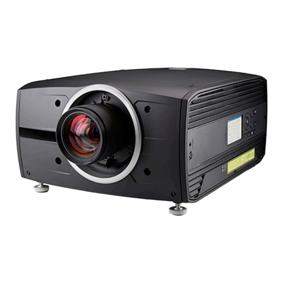
Getting to know the projector. 2.1 Main Components Naming Conventions Back Left Right Front Image 2–1 Projector Items Overview Image 2–2 Item Description Item No. LED Warning Indicator Adjustable Feet Lens Lens Holder IR Receiver. For receiving remote control signals LCD Display Keypad Panel. -
Page 25: Service And Maintenance
2.2 Service and Maintenance General The F70 series does not have any user serviceable parts. All service tasks must only be carried out by the manufacturer, or a Barco authorized service personnel or Barco technicians. 2.3 LED Status Light About The F70 Status Led is located on the rear top of the Projector During normal operation, the LED is not illuminated. -
Page 26: Lcd Panel
Getting to know the projector. 2.5 LCD Panel 2.5.1 LCD panel general About The LCD panel (See chapter 2.6, Local Keypad) is located on the right side of the projector, and has two modes of indication; Mirror of the OSD, and Information display. Toggle between the two indications by using the Menu button on the keypad, or on the remote control 1. - Page 27 Getting to know the projector. • Notifications: The error and/or warning messages that are currently active. If no messages are active, this list will be empty. • Preview: A preview pane of the projected image. If no image is being projected, a test image is displayed instead.
-
Page 28: Dashboard
Getting to know the projector. Image 2–6 Preview page Swipe between the status screens Due to the touch functionality of the LCD screen, it is possible to swipe between the different pages in the information mode. Image 2–7 Example of a Dashboard status screen Mirroring the source input. -
Page 29: Osd Menu Mode
Getting to know the projector. When grey, the function is not enabled. When blue, the function is enabled. See the figure in chapter “LCD Status screens”, page 26 where the dashboard page shows the highlighted Brilliant Color mode, Digital shift and Digital zoom. Symbol explanations are showed in the figure below. -
Page 30: Shortcut Buttons
Getting to know the projector. Image 2–9 Item Description Name LCD Display Shows navigation menu incl. sub menus and projector status screens (dashboard, notification, about and preview). Navigation keys Navigation arrows (up, down, left, right), confirm selection (✓) Menu button Toggle between OSD / Information menu. -
Page 31: Basic Remote Control Unit
About the basic remote In order to make sure you can control your projector remotely, Barco has provided a basic remote control unit in case the Pulse RCU is not available to you. While this remote control has a more limited amount of available features, it will be able to help you out with basic controls. -
Page 32: Platinum Remote Control Unit
Getting to know the projector. Image 2–12 How to open the battery compartment of the remote CAUTION: Replace batteries with the correct battery type. Only use AAA size batteries. There is a risk of explosion if the battery is replaced with an incorrect type. Make sure the polarities match the + and - marks, as depicted on the inside of the battery compartment. -
Page 33: Remote Control, Protocol Setup
Getting to know the projector. Image 2–13 Insert the two AA size batteries, making sure the polarities match the + and - marks inside the battery compartment. Tip: Use alkaline batteries for optimum range and lifetime. Image 2–14 Insert (1) both lower tabs of the battery cover in the gaps at the bottom of the remote control, and press (2) the cover until it clicks in place. - Page 34 The NEC protocol have to be used for Barco projectors based on the Pulse platform: Loki, Balder, F40. F70, F80, F90, HDX 4K, UDX, UDM and more.. • The RC5 protocol have to be use all other Barco projectors: HDX W, HDF W, HDQ 2K, ... (legacy products) How to set Remove the battery cover.
-
Page 35: Functionality Overview
Getting to know the projector. 2.9.3 Functionality overview Remote Control Unit buttons Backspace (while Button pressed indicator. entering values) XLR connector. Shutter Open. Decimal mark (while Shutter Close. entering values) Touch Panel On/Off. Macro button. (Not in (Not in use). use) Menu Back. -
Page 36: Pulse Rcu, Function Of The "Rgb Filter" Button
Getting to know the projector. Image 2–17 2.9.5 Pulse RCU, function of the “RGB filter” button Filtering the color of the projected image By pressing the RGB filter button on the RCU you can place a color filter on the output of the projector. This feature can be useful during the installation and configuration of a multi-projector or multi-channel setup. -
Page 37: Wired Rc Connection
Getting to know the projector. Image 2–19 Enter the Apply button to confirm the action 2.9.7 Wired RC connection About The remote control can also be directly wired to the projector from the stereo jack connector on the remote, (See “Functionality overview”, page 35 ), to the RC connector on the back panel of the projector.(See section “Connector Panel”) -
Page 38: Connector Panel
Getting to know the projector. Broadcast Address Every projector has a broadcast (common) address '0' or '1'. The default address is '0'. The choice between '0' and '1' can be selected in the GUI: “System Settings” → “Communication” →“IR Control “. Placing new batteries in the remote control or plugging the remote to a projector via a cable will automatically reset the address back to its default value '0'. -
Page 39: Color Wheels
The F70 Projector is delivered with a standard Color wheel, that is suitable for most applications. Other colorwheels are available upon request. Consult Barco sales office or a service partner in order to find the most suitable colorwheel for the specific application. - Page 40 Getting to know the projector. Image 2–22 The F70 Flight Case is a custom designed container, that is suitable for shipping the projector, including flight frame, signal and power cords and up to two lenses. The case is fully-lined to protect the projector and lenses during transit and storage. 601–426 /17 F70 Series...
-
Page 41: Lenses, Handling And Features
Lenses, Handling and features Approved Lenses .........................42 Lens range...........................42 Replace a lens ..........................45 Lens calibration ..........................47 Installing the lens safety cable .......................48 Preparing the FLDX lens (0.38:1) UST ...................51 Mounting the FLDX lens (0.38:1) UST lens with a lens support............55 Mounting a safety cable to the FLDX lens (0.38:1) UST lens ............58 About 601–426 /17... -
Page 42: Approved Lenses
Lenses, Handling and features 3.1 Approved Lenses Approved Lenses Description Compliance Partnumber R9801214 FLD 1.6 - 2.32 : 1 (EN11) approved R9801218 FLD 0.74 : 1 (EN12) approved R9801228 FLD 1.24 - 1.6 : 1 (EN13) approved R9801209 FLD 2.37 - 3.79 : 1 (EN14) approved –... - Page 43 Lenses, Handling and features Description Weight Name Part number FLD Lens 1.6 - 2.32 : 1.6-2.32 : 1 (WUXGA) R9801214 2.2 kg 1 (EN11) FLD Lens 0.74 : 1 0.74:1 (WUXGA) R9801218 1.9 kg (EN12) FLD Lens 1.24 - 1.6 : 1.24 - 1.6 : 1 (WUXGA) R9801228 2.6 kg...
- Page 44 Lenses, Handling and features EN41 EN42 EN43 EN44 EN45 EN46 Image 3–2 Description Weight Name Part number FLD+ Lens 1.7 - 2.5 : 1 1.58 - 2.33 : 1 (WUXGA) / 1.7 - 2.5 R9801216 2.54 kg (EN41) : 1 (WQXGA) FLD+ NV Lens 1.7 - 2.5 : 1 IR Optimized, 1.58 - 2.33 : 1 R9801216...
-
Page 45: Replace A Lens
Lenses, Handling and features Focal Length Focus Range Working F# Name Iris / Iris F# Zoom Ratio (mm) FLD+ NV Lens 2.4-2.7 Yes 2.4-6.5 1.42 23.95-34.02 1.5 - 15 1.2 - 1.7 : 1 (NV43) FLD+ Lens 2.5 2.1-2.93 Yes 2.1-6.5 1.85 49.52-91.60 2.5-25... - Page 46 Lenses, Handling and features Image 3–3 Install a lens Verify that the projector shutter is activated (shutter is activated when the shutter icon on the projector keypad is red). Verify that the lens release lever is in its default position at the far left of the slide, as illustrated. Remove the protective cap at the lens bayonet end Align the lens so that the red marking on the bayonet is facing upwards.
-
Page 47: Lens Calibration
Lenses, Handling and features Image 3–5 3.4 Lens calibration When to calibrate the lens The EN6X series lenses has a functionality that memorize the positions of focus, zoom and iris. In order to obtain the correct position, the lens has to be calibrated when installed. How to calibrate Enter the menu Settings / Maintenance / Lens calibration The calibration menu shows up, with a question mark for each of the functions that has to be calibrated. -
Page 48: Installing The Lens Safety Cable
Lenses, Handling and features Repeat for each calibration item. 3.5 Installing the lens safety cable When to use the lens safety cable The lens safety cable must be used in any circumstance where the projector is mounted above people. Do this to secure the mounted lens in the lens holder. - Page 49 Lenses, Handling and features Image 3–9 Image 3–10 Snap the first loop end of the safety cable into one of the following clips and let the loop end point downwards. 1. Configuration A: Use the upper clip on the side of the cable bundle (reference 2, Image 3–9).
- Page 50 Lenses, Handling and features Image 3–12 Example of Configuration A Image 3–13 Example of Configuration B Close the U-bolt and tighten it. Note: Make sure the safety cable is tightened around the lens before tightening the U-bolt nuts. Place the shackle through the free loop end of the safety cable. Connect the shackle on the truss or rigging frame.
-
Page 51: Preparing The Fldx Lens (0.38:1) Ust
Lenses, Handling and features Image 3–16 Carefully slide the safety cable through the cable clips. Make sure the cable is placed between the motor block and the cover plate. Slide the cable through the loop end at the beginning of the cable. Mount a U-bolt on the cable, with the open ends oriented outwards (reference 3, Image 3–16). - Page 52 Lenses, Handling and features Image 3–18 Do not use for projection to the left when mounted in a frame. Image 3–19 Required tools Allen key 2 mm with long shaft (delivered with the kit) How to prepare the lens Place the lens on a table. Turn out the 6 screws (1). Use an Allen key with a long shaft so that you do not damage the screw head.
- Page 53 Lenses, Handling and features Image 3–20 Image 3–21 Slide the motor housing a few mm to the backside of the lens (2) to disengage focusing gear and motor gear. Disengage Slide range: 5mm max Motor gear Focusing gear Motor unit Image 3–22 601–426 /17 F70 Series...
- Page 54 Lenses, Handling and features Image 3–23 reference marking Rotate the motor housing until the chosen marker on the housing corresponds with the reference marking on the lens body (steps of 30°). See if the mounting holes matches the holes in the lens body. E.g., if you want to project to the left, then turn the motor housing until the left marking on the motor housing corresponds with the reference marking on the lens housing.
-
Page 55: Mounting The Fldx Lens (0.38:1) Ust Lens With A Lens Support
Lenses, Handling and features Image 3–25 Side view Top view Up projection for any projector: Image 3–26 Side view Bottom view 3.7 Mounting the FLDX lens (0.38:1) UST lens with a lens support How to mount Turn the projector on its side or on its top cover. Place the bottom support plate on the bottom plate of the projector. - Page 56 Lenses, Handling and features Image 3–27 Mount the bottom plate Turn in both M6 screws and the M4 screw. Turn the projector back on its feet. Slide the lens locking system to the left. Insert the lens. Make sure the electric contact points (C) on the lens match the contact points on the lens holder.
- Page 57 Lenses, Handling and features Image 3–29 When the lens is on its place, close the lens locking system by moving the handle from the left to the right. Project an image and adjust the shift. See projector’s user manual for more information about lens shift. Note: Shift cannot be adjusted anymore after full installation of the complete kit.
-
Page 58: Mounting A Safety Cable To The Fldx Lens (0.38:1) Ust Lens
When mounting the UST lens in a projector without using the mounting support (not recommended), it is mandatory to use the safety cable set provided by Barco instead. Failing to use either the correct type of safety cable or the mounting support may damage the lens and/or projector, and can also cause serious injury to persons. - Page 59 Lenses, Handling and features How to prepare the lens with the safety cable Stick 3 to 4 clips on the surface of the lens body (1). Snap the first loop end of the safety cable into one of the clips. Image 3–33 Slide the rest of the cable around the lens.
- Page 60 Lenses, Handling and features 601–426 /17 F70 Series...
-
Page 61: Physical Installation
Physical Installation Installation process ........................62 Installation conditions........................62 Initial inspection..........................63 Positioning the projector........................64 Mounting the projector, general considerations ................64 Projector safe attachment points....................66 Throw distance..........................67 Scheimpflug (Boresight) introduction....................69 Scheimpflug adjustment procedure ....................70 About This chapter describes the physical conditions and procedures required when installing the F70 projector. It also describes the outlines and some of the considerations that should be taken in to account when designing and setting up the installation. -
Page 62: Installation Process
4.2 Installation conditions Environmental Conditions Barco projectors are manufactured according to specific design standards, which also include environmental conditions. Failing to follow the terms and conditions outlined in this chapter can result in loss of product warranty The table below summarize the physical environments in which the projector may be safely operated or stored. -
Page 63: Initial Inspection
Upon receipt of the projector, we recommend that customers inspect the projector for any signs of damage that may have occurred in transit. If damage is found, file a claim with the shipping carrier immediately. Notify the Barco Sales and Service office, or your preferred Barco agent, of the damage as soon as possible. Box Contents Your projector box should contain the following: •... -
Page 64: Positioning The Projector
Physical Installation 4.4 Positioning the projector CAUTION: The position and physical securing of the projector must be sufficient to prevent it from accidental or involuntary movement. Proper securing of the projector is the responsibility of the installer and user. The Projector are heavy, and can cause severe damage and injuries if falling. General guidelines Proper positioning of the projector lessens the overall picture setup time, and ensures a better image with fewer artifacts. - Page 65 Physical Installation In addition, four mounting inserts are located on the bottom of projector. See“Projector safe attachment points”, page 66 Where possible, the projector lens must be positioned exactly perpendicular to the center of the screen. Use the projector offset (lens shift), rather than physical angling, to correct any off-center positioning.
-
Page 66: Projector Safe Attachment Points
Physical Installation Power up the projector. Go to Main Menu / Installation / Orientation and select the correct orientation for your setup. Go to Main Menu / Test Patterns and select an internal hatch pattern to display on the screen. Adjust the position (height and angle) of the rigging frame until the projected hatch pattern is a level and perfect rectangle. -
Page 67: Throw Distance
Physical Installation Max Hole Depth Application Item Thread Dimension 16mm Anchorpoint / Ceiling / Rig Mount 4.7 Throw distance Calculate the installation throw distance Throw is the distance (D) measured from your projector lens to the screen. To calculate the throw distance for an installation, you will need two pieces of data: the selected lens throw ratio (L) and the horizontal width (W) of the screen. - Page 68 Physical Installation Throw distance, FLD+ / FLDX WQXGA / 4K UHD Image height Image width Screen diagonal 14.00 7.50 12.00 7.00 13.00 11.00 6.50 12.00 10.00 6.00 11.00 9.00 5.50 10.00 5.00 8.00 9.00 4.50 7.00 8.00 4.00 6.00 3.50 6.00 5.00 3.00...
-
Page 69: Scheimpflug (Boresight) Introduction
Physical Installation Throw distance, FLD+ / FLDX WUXGA Image width Screen diagonal 14.00 12.00 7.50 13.00 7.00 11.00 6.50 12.00 10.00 6.00 11.00 9.00 5.50 10.00 5.00 8.00 9.00 4.50 7.00 8.00 4.00 6.00 3.50 6.00 5.00 3.00 5.00 2.50 4.00 4.00 2.00... -
Page 70: Scheimpflug Adjustment Procedure
Physical Installation Scheimpflug principle The "plane of sharp focus" can be changed so that any plane can be brought into sharp focus. When the DMD plane and lens plane are parallel, the plane of sharp focus will also be parallel to these two planes. - Page 71 Image 4–8 Preparation Prepare the test area. Barco recommends a projector-screen according to the table “Lens distance” above to be used for all Scheimpflug adjustments. Verify that the throw ratio of the installed lens matches the requirements of the installation area (projection distance and screen size).
- Page 72 Physical Installation Image 4–10 Adjust the right side Scheimpflug adjustment screw (reference 2 in the next figure) until the test image in the top right side of the screen is in focus. Use a size 4 hex key to do this. Note: This process may cause the other areas of the image to slide out of focus.
-
Page 73: Getting Started
Getting started Projector source and control connections ..................74 Power up the projector ........................77 Power down the projector......................78 Power mode transitions.........................78 Power modes ..........................80 Customize projector settings ......................80 User interface..........................80 About this chapter This chapter describes how to set up and optimize your projector setup when the physical installation process is complete. -
Page 74: Projector Source And Control Connections
Getting started 5.1 Projector source and control connections 5.1.1 Making connections The source switching time is variable and could take few seconds.. Source signal connectivity The connector panel at the back of the projector is used for all source connections. Source signal connectivity on the projector is: •... -
Page 75: Specifications Hdmi 2.0
Getting started Parameter Value Max. input data resolution 2560x1600@120Hz WQXGA / 3840x2400 @60Hz (4K ) Max Bit depth 8, 10, 12 bit EDID Supported HDCP Supported 5.1.2.3 Specifications HDMI 2.0 Specifications Regarding HDMI 2.0: The decryption protocol HDCP 2.2 are enabled and valid in this unit. Parameter Value Connector... -
Page 76: Control Interface Specifications
Getting started Specifications Parameter Value Reference specification HDBaseT 1.0 Specification, June 2010 Connector Standard RJ-45, 8P8C Signal characteristics HDBaseT Max. cable length (1080p/48b/60Hz) 100 m (Cat5e/6), Pixel Clock <=225HHz, Video Datarate <=5.3Gbps 70 m (Cat5e/6), Pixel Clock >225HHz, Video Datarate >5.3Gbps 100 m (Cat6a/7), Pixel Clock >225HHz, Video Datarate >5.3Gbps Max TMDS Clock Frequency... -
Page 77: Lan/Ethernet
Getting started 5.1.3.2 LAN/Ethernet Specifications Parameter Value Ethernet connector 1 RJ45 Connector for projector control (not content) Protocols DHCP, TCP/IP, UDP/P Speed 10/100 Mbit/1000Mbit 5.1.3.3 USB-A port Specifications Parameter Value USB connector Type A Function Firmware upgrade using USB sticks Power Power 5V, max 1,5A (out) Standard... -
Page 78: Power Down The Projector
Getting started Power up the projector using the keypad or remote Connect the line cord to the projector. Plug the 3–pronged cord into a grounded AC outlet. The projector will begin warming up, and the backlight of the Standby /power button are flashing white. When the backlight on the standby button are constant white, the projector are in standby mode, ready to be switched on. -
Page 79: Power On Projector
Getting started Projector mains powered Auto transition after x minutes if ECO mode enables Press power On/Off button, remote On/Off button 5.4.2 Power on projector If not already connected, connect the female side of the power cord with the power input socket of the projector. -
Page 80: Power Modes
Getting started The WOL is performed by sending a Magic Packet followed by the projectors MAC address. The MAC address is found in the Menu / Settings / Communication / LAN. menu. The MAC address is similar to the HW address that is shown in this menu path. - Page 81 Getting started User access levels The projector’s software platform uses access levels to define what each user can do. There are two user access levels: Standard User and Power User. In addition, there is a Service user access for certified Service personnel. A standard user has access to all projector functionality and OSD menu items.
- Page 82 Getting started 601–426 /17 F70 Series...
-
Page 83: Source Menu
Source menu Connector selection ........................84 Connector settings........................84 Using dual inputs ..........................86 No source image ..........................87 About the Source menu This menu is used to select, review and configure sources into the projector. Enables either via the source menu, or the shortcut key. By navigate through the Source menu, it will be visible also on the OSD. -
Page 84: Connector Selection
Source menu 6.1 Connector selection About Home/Source Image 6–2 Observe that the HDCP compatibility for each input is noted in the input icon. See chapter 5.1 “Projector source and control connectors”. for input source specifications. Click on the relevant input connector icon to swap or activate the source. The icon for the active source is highlighted. - Page 85 Source menu How to configure a connector Press Menu to activate the menus and select Source. Image 6–3 Select source Press OK. The Source menu is displayed with the actual available sources filled out. Image 6–4 Source menu Scroll down to the bottom of the list of available sources and select Connector Settings. Image 6–5 The available input connectors are displayed.
-
Page 86: Using Dual Inputs
Source menu Image 6–6 The Connector Settings menu for this connector will be displayed. Image 6–7 Example of connector settings of an Displayport Connector. You can change the following: • To force a limit on the color space, select one of the available color spaces. •... -
Page 87: No Source Image
Source menu For Images to be displayed in this mode, the resolution must be the same on both channels Signal source setup. When using dual inputs, it is important that the signal sources are set up correctly, with the correct resolution. Please refer to the manual for the source itself (PC, Graphic driver card..) in order to obtain a correct setup. - Page 88 Source menu Image 6–11 Source menu, No Source image The No source image menu is displayed. Image 6–12 Example of the No source image menu Select the desired image to project when no source image is available. When custom background images have been uploaded using an external tool, they will be listed after the predefined images.
-
Page 89: Image Menu
Image menu Contrast............................91 Brightness............................91 Saturation ............................92 Sharpness ...........................92 Gamma adjustment ........................93 Gamma Types..........................94 Digital Zoom Shift .........................95 Advanced image adjustments......................97 About Image adjustment menus There are different menu pictures showing up for the LCD display and the OSD. For the LCD display, the menu is shown below. - Page 90 Image menu Entering Contrast, Brightness, Saturation, Sharpness or Gamma menus from the keypad. When entering any of these menus from the Keypad, the screen below will show up in the LCD panel. Use the arrow keys to select and adjust the values. Image 7–2 When pressing enter on the value slider, this icon will show up on the OSD (depending which setting that is enabled, contrast showed here).
-
Page 91: Contrast
Image menu 7.1 Contrast About Image / Contrast Used to adjust the contrast ratio of the displayed image by applying gain to the red, green and blue signals. Available range: 0.00 to 2.00 Default value: 1.00 Image 7–4 When inside this menu, it is possible to change to the other image adjustments (Brightness, Saturation, Sharpness and Gamma) by using the up and down arrows on the remote control or keypad. -
Page 92: Saturation
Image menu 7.3 Saturation About Image / Saturation Saturation levels impact on the white levels and the intensity of the color display; the higher the value, the more vivid the color display will be. Available range: —1.00 to 2.00 Default value: 1.00 Image 7–6 Saturation OSD menu 7.4 Sharpness About... -
Page 93: Gamma Adjustment
Image menu Image 7–8 Effect of sharpness adjust 7.5 Gamma adjustment About gamma correction. Gamma compensation, or gamma correction, is a way of adjusting the signal input to light output characteristics of a display or projector in order to suit the eye’s sensitivity to different light levels and to compensate for non-linearities in displays. -
Page 94: Gamma Types
Image menu Image 7–10 7.6 Gamma Types 7.6.1 Predefined Gamma types About The Gamma Type selection contains several predefined Gamma settings for the most common user cases. How to select Gamma type Enter the menu Image / Gamma Press enter, and scroll horizontally in the menu and select the proper Gamma value. Image 7–11 Select the gamma type that match the setup in the source to obtain an optimal rendering. -
Page 95: Digital Zoom Shift
Image menu The DICOM function is used to simulate DICOM gammas at a few selected max light outputs, and assumes that both ambient light and the projector black is 0 cd/m2. How to select the optimal DICOM Gamma Enter the menu Image/Gamma Scroll horizontally in the menu and select a DICOM value that is closest to the value from the source. -
Page 96: Digital Zoom
Image menu 7.7.1 Digital Zoom Digital Zoom This function will zoom the picture digitally. When zooming in, the center of the image will increase in size. This means that the outer part of the picture will be outside the projectors picture frame. When zooming out, the result is that the picture will be smaller than the projectors picture frame. -
Page 97: Advanced Image Adjustments
Image menu The numbers on the right side of the menu represent the movement (shift) of the picture in pixels referred to the “no shift” position. Positive numbers are shift right/down, and negative numbers are shift left/up. This function can also be used in combination with the Digital zoom function. Image 7–17 Original Picture, not digitally shifted Image 7–18 Picture shifted horizontally Image 7–19 Picture shifted vertically... - Page 98 Image menu Image 7–20 Image 7–21 The P7 menu is displayed. Choose one of the pre-defined presets: • Native: Projector native color settings. Default setting • EBU: European color standard for broadcasting • SMPTE-C: American color standard for broadcasting. • Rec.
-
Page 99: Edit The Realcolor Presets
Image menu Image 7–24 Select the desired Mode. Choose one of the following custom options: • Custom RGB: 3–point color configuration. In RGB mode, the C, M and Y coordinates will be calculated automatically based on the R, G and B coordinates. -
Page 100: Output Resolution 4K
Image menu The edited presets can be reset to the original values by enter the Reset button. There is also a possibility to copy the values to the custom preset. To reset the values in Custom presets, enter the “Reset to native” button when in Custom mode Image 7–25 Preset Native selected Image 7–26 Editable values 7.8.3 Output resolution 4K... -
Page 101: Smear Reduction
Image menu Image 7–27 Output resolution menu 7.8.4 Smear reduction About Smear is a phenomenon that typically occur when objects in the picture moves in high speed over the screen. It appears like there is a “tail” behind the object, or a lag in the moving parts of the picture. In order to avoid this, there has been developed a Smear Reduction Process (SRP ), that reduces this perceived rendering. - Page 102 Image menu Image 7–29 This menu is only valid for COLOR colorwheel in WQXGA@60Hz mode. For BRIGHT colorwheel, there are only two choices in the menu; Off and Native. (See table below) Menu choices of SRP and Brilliant Color matrix with COLOR colorwheel installed. Valid when COLOR colorwheel is installed.
- Page 103 Image menu Mode Brilliant Color Native BSI (Black Sub Frame Insertion) Video Graphics SRP Half BSI Native SRP Half Plus BSI Native 4K @ 60Hz Video SRP Off Native Video SRP Half Native SRP Half Plus Native Menu Choices Menu choices of SRP and Brilliant Color matrix with BRIGHT colorwheel installed. Mode Brilliant Color WQXGA @60Hz...
-
Page 104: Displaying Hdr Content- Perceptual Quantizer (Pq)
Image menu Mode Brilliant Color Native Video SRP Half Native Video 4K mode SRP Off Native Video SRP Full Native Video 7.8.6 Displaying HDR content– Perceptual Quantizer (PQ) About PQ Perceptual Quantizer (PQ) is a non–linear electro-optical transfer function (EOTF) that allows for the display of High Dynamic Range (HDR) content with a luminance level of up to 10 000 cd/m²... -
Page 105: Hdr Status
Image menu Image 7–31 Select the desired Unit (nits or foot-lambert). Enter the Screen luminance (either in nits or foot-lambert). Alter the HDR boost if necessary. You can modify this value to somewhere between 0.8 and 1.2. 7.8.7 HDR Status. About HDR status When an active source is HDR, an icon is visible in the status menu. - Page 106 Image menu This function is only available for the FS variants of the projector. How to swap channels Select the Menu/ Image / Advanced / Night Vision. menu Toggle the Swap channel function on / off by pressing the OK button on the remote control or the keypad. Image 7–34 601–426 /17 F70 Series...
-
Page 107: Installation Menu
Installation menu Position ............................. 108 Lens ............................110 Scaling modes..........................113 Warping ............................. 115 Blending ............................ 126 CLO feature ..........................133 IR / Night vision functionality......................137 Illumination ..........................138 3D setup / IG pixel shift ....................... 139 Menu overview Image 8–1 601–426 /17 F70 Series... -
Page 108: Position
Installation menu 8.1 Position 8.1.1 Orientation What can be done? The way of physical installation of the projector can be defined to the projector. The following installation are possible: • Desktop front: Projected image will not be flipped or mirrored. •... -
Page 109: Projector Tilt Indication
Installation menu Use the ◄ or ► keys to select the projector orientation mode and press OK to activate. 8.1.2 Projector tilt indication When to use the tilt sensor menu The projector has a built-in tilt sensor that detects the angle at which the projector is mounted. If you are in a situation where you need to fine-tune the projector because you want to achieve a picture at a specific angle (e. -
Page 110: Lens
Installation menu 8.2 Lens 8.2.1 Zoom / Focus Zoom and focus Enter the menu Installation / Lens / Zoom Focus Use either the keypad arrows, or the remote control for this operation. Use the navigational arrows, up and down, to adjust zoom. Use the navigational arrows, left and right, to adjust focus. -
Page 111: Shift To Center
Installation menu Use the left, right, up and down navigational arrows to adjust the lens shift in four directions. This feature moves the picture optically within the shift range of the lens optics. Press the right key to enable shift, and use the arrow keys on the remote control, or the keypad to move the picture in vertical and horizontal directions. -
Page 112: Iris
Installation menu Image 8–9 From the keypad Press the Lens button on the keypad. A menu picture as shown below shows up. Press the ✔ button for 3 seconds. 8.2.4 Iris General Iris controls the contrast and focus depth of the image. Decreasing the iris will increase contrast and image depth, at the same time as it decreases brightness. -
Page 113: Scaling Modes
Installation menu Image 8–10 8.3 Scaling modes General For the modes Fill Screen and Stretch, the screen size must be defined, see chapter “Warping Screen Size”. The purpose of the scaling mode is to adapt the image on the screen in an optimal way, based on the desired rendering. - Page 114 Installation menu Input signal (Source): 4 : 3 DMD Capacity: 1,6 : 1 (2560 x 1600 pixels) Screen: 2,35 : 1 (Cinemascope) Image 8–12 Fill Screen This mode utilizes the defined screen size, and keeps the aspect ratio. Input signal (Source): 4 : 3 DMD Capacity: 1,6 : 1 (2560 x 1600 pixels) Screen: 2,35 : 1 (Cinemascope) Image 8–13...
-
Page 115: Warping
Installation menu Select the desired mode and press OK button on the remote control or keypad. Image 8–15 8.4 Warping 8.4.1 About warping About Image warping is the process of digitally manipulating an image to compensate for the distortion of the screen, typically by non perpendicular alignment of the projector versus the screen. -
Page 116: Warping - On/Off
Installation menu Distorted Picture Ideal Picture Image 8–16 8.4.2 Warping – On/Off About warping on/off By toggling between on and off the warping functionality can be enabled or disabled. How to toggle In the main menu, select Installation → Warp. Image 8–17 Installation menu, warp The Warp menu is displayed. -
Page 117: Warping - Screen Size
Installation menu Image 8–18 Example of the Warp menu In the Warp menu, click Warp to toggle between On and Off. Image 8–19 Image 8–20 8.4.3 Warping – Screen size About (Warp) Screen Size adjustment If the used screen aspect ratio is different than the projector aspect ratio, e.g. source is 16:9 and projector is 16:10, then black bars will be projected. -
Page 118: Warp - 4 Corners Adjustment
Installation menu The Screen Size menu is displayed. Image 8–22 Select the pre defined aspect ratio that suits the aspect ratio of the screen. Set the screen size width and height to match the measurement of the screen. Note: It is only the ratio between the width and height that is used, so the values may be entered as the screen aspect ratio or actual measurement in cm, inches or any other unit. - Page 119 Installation menu Image 8–24 How to adjust the image. From the warp menu, select the menu Installation/Warp/4 Corners. Select and enter the Helper lines slider. A yellow frame will be visible. To enable the 4 Corners Warping, Set the Warp slider to the right position. (Select and enter). Enable the corner that must be warped (Select and enter).
-
Page 120: Warping - Bow
Installation menu 8.4.5 Warping – Bow About bow adjustment A bow distortion can be adjusted so that a normal image is displayed. Positive adjustments angles introduce more outside bow distortion. Negative adjustments introduce more inside bow distortion. Image 8–27 Bow distortion Symmetric bow correction In the main menu, select Installation/Warp. - Page 121 Installation menu Image 8–30 Symmetric Bow correction. To enable a symmetric adjustment, make sure the Symmetric slider is set to On. Image 8–31 The slider is enabled when set to the right and when it is colored blue. Select the side of the picture to be bow corrected, confirm by pressing enter, and use the arrow keys to adjust the angle and linearity (length) of the vectors.
- Page 122 Installation menu Non symmetric bow correction Enter the Bow menu, and disable the symmetric slider. There are now two vectors on each side of the picture that can be adjusted individually. Select each of them, and adjust angle and linearity (length) individually to obtain the correct correction. The angle is adjusted by the up and down arrows on the remote control, and the linearity is adjusted by the left and right arrows Image 8–33 Left vector of the upper side of the picture.
-
Page 123: Warping - Warp Files
Installation menu Repeat the step for each side of the picture that must be corrected. Definition of angle and linearity (length) in the bow warp procedure Image 8–36 To reset the bow adjustments, select Reset and press the OK button. 8.4.6 Warping –... -
Page 124: Warping - Latency Control In A Multi Projector Setup
Installation menu Image 8–38 Warp menu, Warp files The Warp Files menu is displayed. Image 8–39 Example of the Warp files menu Make sure the Enable slider is set to right. Select the desired warp file. Image 8–40 Example of the Warp files menu 8.4.7 Warping –... - Page 125 Installation menu Functional description Every projector in a multi–projector setup will have a different latency. This latency depends on the amount of warp and on the frequency of the projected image. In order to have no visible difference in the overall projected image, the user needs to be able to control the latency of each projector.
-
Page 126: Blending
Installation menu Image 8–44 Example of the Transport delay menu Enter the value either by the arrow keys (one step at a time) or directly by the numeric keys on the remote control. Click Apply to confirm the value. Repeat this process for every projector in the setup. 8.5 Blending 8.5.1 Introduction to blend functions When to use blend functions... -
Page 127: Set Up The System
Installation menu 8.5.2 Set up the system How to set up the system In this chapter, the setup procedure for the projectors is explained, but a setup procedure must also be performed for the picture source. In order to obtain a satisfying result for the Blend function, the overlap / Blend zone are recommended to be at least 10% of the picture width. -
Page 128: Basic Blend Setup Procedure
Installation menu Adjust the value by using the arrow keys. (See note below). Repeat step 4 and 5 to adjust the rest of the blending zones. Exit the menu by using the exit button on the remote control. 8.5.4 Basic blend setup procedure Basic blend adjustment procedure Entering the Basic blend Adjustment from the Menu/Installation//Blend and mask/Basic blend menu, either by the remote control, or the keypad on the projector. -
Page 129: Black Level Setup Procedure
Installation menu Adjustment procedure in over / under configuration. For Blend adjustments in over / under configuration, the procedure is the same as for side by side, but use the Top and Bottom height instead, and perform a similar procedure. Use the numeric keys instead of the arrow key to set the values. -
Page 130: Color Level Adjustment Procedure
Installation menu Image 8–49 Move the cursor to the side where the overlapped area occurs. (Left/right/top/bottom.) For the left projector, this will typically be the right side in the menu as an example. Press enter, and adjust the value with the arrow keys. The icon shown below will appear on the OSD when the side is selected. -
Page 131: Black Level Files
Installation menu different black levels: one for the zone where only the picture of the left projector (zone 1), one for the Blend zone (zone 2), and one for the zone where there is only the picture of the right projector (zone 3). Picture Left Blend Zone Picture Right... -
Page 132: Blend Files
Installation menu How to activate an uploaded Black Level adjustment file? In the main menu, select Installation / Blend and mask / Black level files Image 8–53 Blend menu, Black Level Files The Black Level Files menu is displayed. Files will be listed in this window Image 8–54 If any custom Black Level adjustment files are available, select the desired file. -
Page 133: Advanced Blend
8.6.1 Introduction Introduction The CLO (Constant Light Output) is a Barco Pulse software feature for maintaining a stable light output from the projector over time, by automatically adjusting the light source. The CLO feature utilizes a light sensor placed internally in the projectors light path. -
Page 134: Using The Clo Features
Installation menu 8.6.3 Using the CLO features 8.6.3.1 CLO feature in the OSD, Prospector and API CLO feature in the OSD Navigate to Installation — Illumination Image 8–57 CLO feature from Prospector Navigate to Settings — Illumination Image 8–58 CLO feature from API •... -
Page 135: Example For Using The Clo Feature For Maintaining Brightness Over Time
Installation menu 8.6.3.3 Example for using the CLO feature for maintaining brightness over time Maintaining the brightness • Adjust lightsource power to desired setting, e.g. 80% • Enable the CLO • The projector will maintain the brightness at 80% The CLO adjusts the power to the light source to maintain the light output over time. As there is a degradation over time in both optical components and light source, the time frame the CLO can maintain the light output is dependent on how much initial headroom is available. -
Page 136: Example: Clo Scale With One Projector
Installation menu CLO, typical user cases To linearly dim the projectors and / or using the same dim value on all projectors in a multi-channel configuration when e.g. going from a day scene to a night scene. 8.6.4.2 Example: CLO scale with one projector Example: CLO scale with one projector •... -
Page 137: Ewma
8.6.7 Setpoint Setpoint This feature enables the user to set the desired value directly. As no max value is given Barco recommends using the CLO scale if different output power settings are needed when using the CLO. The setpoint can be set and/or monitored using the property: •... -
Page 138: Illumination
Installation menu How to enable IR/Night Vision. Enter the Menu/ Installation / Illumination menu. This menu shows two sliders; one for the LED Desired power (daylight), and one for the IR LED Desired power (Night Vision). The sliders are scaled from zero – 100% power. -
Page 139: Setup / Ig Pixel Shift
Installation menu Image 8–62 8.9 3D setup / IG pixel shift About All sub-menus, except from the IG Pixel shift, are described in other topics in this manual, where they more naturally belong. 8.9.1 IG pixel shift General IG pixelshift is a feature where the Image Generator can process the image in two channels. This two input channels have different positions of the pixelshift module. -
Page 140: Ig Pixelshift Night Vision
Installation menu Image 8–64 Display setup Menu Use the up / down arrow keys on the remote control to move the cursor to the “Display mode” position. Use the left/right arrow key to scroll to IG pixelshift. Select by pressing enter. Status menu When IG pixelshift is enabled, it will be visible in the Status Menu. -
Page 141: Autostereo (3D) Setup
Installation menu Image 8–66 Image 8–67 8.9.3 AutoStereo (3D) Setup Enabling 3D mode See chapter “3D”, page 181 for 3D mode setup 601–426 /17 F70 Series... - Page 142 Installation menu 601–426 /17 F70 Series...
-
Page 143: Gui - Profiles
GUI – Profiles Profiles introduction ........................144 Saving the current projector settings in a profile ................145 Assigning a created projector profile to a preset ................146 Deleting a projector profile......................148 601–426 /17 F70 Series... -
Page 144: Profiles Introduction
GUI – Profiles 9.1 Profiles introduction About Profiles The profile function makes it possible to store different profiles / projector setups for different use cases, and quickly recall them when needed. This means that it is not necessary to enter a lot of different menus to adjust the projector setup for specific recurring use cases. -
Page 145: Saving The Current Projector Settings In A Profile
GUI – Profiles Profile domain Settings saved name Warp • Warp status enabled / disabled • Screen size • Warp file selected (if available) • Transport delay Note: Bow and 4 corners warp cannot be saved. Blend • Blend mask enabled / disabled •... -
Page 146: Assigning A Created Projector Profile To A Preset
GUI – Profiles Image 9–3 Profile edit menu Use the arrow keys to select New Profile... and confirm. The New Profile pane is expanded and fully displayed. Image 9–4 Example of the new profile pane Use the arrow keys and the OK key to select any of the settings you wish to save in this macro. Select the field next to Profile Name and confirm with the OK key to make a keyboard prompt on the projector display. - Page 147 GUI – Profiles Image 9–5 Profiles menu, edit The edit menu is displayed. Image 9–6 Example of the Profile edit menu Select the desired projector profile from the list and confirm. The profile pane for the selected profile will expand. Image 9–7 Example of a projector profile with available preset slots Use the arrow keys to select a preset slot and confirm with the OK key.
-
Page 148: Deleting A Projector Profile
GUI – Profiles Image 9–8 Example of projector profiles allocated to preset slots (here slot 00 and 04) 9.4 Deleting a projector profile How to delete a profile In the main menu, select Profiles → Edit. Image 9–9 Profiles menu, edit The edit menu is displayed. - Page 149 GUI – Profiles Image 9–11 Example of a projector profile with available preset slots Use the arrow keys to select Delete and confirm. confirm the delete action. 601–426 /17 F70 Series...
- Page 150 GUI – Profiles 601–426 /17 F70 Series...
-
Page 151: System Settings Menu
System settings menu 10.1 Communication .......................... 152 10.2 User interface..........................158 10.3 Date and time..........................160 10.4 Power saving settings ......................... 163 10.5 Lens features ..........................166 10.6 Maintenance ..........................166 10.7 Lens calibration .......................... 167 10.8 Reset............................167 10.9 Controlling the backlight of the LCD Display.................. 169 Menu overview Image 10–1 601–426 /17... -
Page 152: Communication
System settings menu 10.1 Communication 10.1.1 Communication About Settings / Communication / LAN Network connection is required to communicate with the projector via LAN or Internet. Current Ethernet communication information is given, and can be edited in this menu. Default mode for Ethernet communications are: Automatic ON / IP Version 4 DHCP mode. Setting Description Automatic... -
Page 153: Projector Address
System settings menu Image 10–3 Communication menu, Remote Control The Remote control menu is displayed. Image 10–4 Example of the Remote control menu To change the broadcast address select the radio button of your choice. The following choices are possible: •... -
Page 154: Ir Sensors
System settings menu Image 10–6 Example of the Remote control menu Select the projector address and select a new address. Select APPLY and click OK to apply the changes. From now on the projector will only listen to this new address and to its broadcast address. 10.1.2.3 IR sensors What can be done? The projector has IR sensors on different sides of the projector. -
Page 155: Host Name - Custom Projector Name Setup
System settings menu Image 10–8 Example of the Remote control menu To disable an IR sensor, select the slider and drag to the left. Tip: A blue slider means an active IR sensor. A gray slider means an inactive IR sensor. Select APPLY and click OK to apply the changes. -
Page 156: Dmx
System settings menu Image 10–10 Example of the host name menu Press confirm to edit the Host name field. Use the digital keyboard to change the Host name to the desired custom name. Press the OK key, or press the enter icon to confirm the typed name. Click Apply to update the host name. 10.1.4 DMX About the ways to control the projector via DMX DMX signals can be connected to the DMX In port on the communicator interface when using a standard DMX... -
Page 157: Trigger
System settings menu How to set up DMX? In the main menu, select Settings / Communications / DMX. Image 10–11 The DMX menu is displayed. Image 10–12 Choose the desired DMX mode. Choose the desired starting channel. Choose whether or not you want the Auto power-down feature to be enabled. If enabled, determine the time-out. -
Page 158: User Interface
System settings menu Image 10–13 F40 series trigger menu The time of trigger output is defined via an API code. Contact Barco support for detailed info. 10.2 User interface 10.2.1 Language Setting the menu language The menu language can be changed to a suitable language. -
Page 159: Units
System settings menu Image 10–15 Select theme, dark or light. 10.2.3 Units About Enter the menu Settings / User interface / Units Units are used to set the preferred units of measurements for temperature and distance. Enter the menu and select the preferred units by the arrow keys on the remote control. Temperature units: Celsius (C) and Fahrenheit (F). -
Page 160: Date And Time
System settings menu Image 10–17 Back light Defines for how long the LCD and buttons backlight will be in on state. Use the navigation arrow keys to select and confirm the selection. Stealth mode The Stealth mode can be enabled via the OSD and API. Prospector can also be used when available. (Q423). In addition, the Stealth mode can be enabled/disabled by pressing the OSD on/off button on the keypad for 5 seconds. -
Page 161: Date And Time Setup - Automatically
System settings menu Image 10–18 Settings menu, Date and time The Date and time menu is displayed. Image 10–19 Example of the Date and time menu Disable the Automatic slider. Gray slider: automatic is off Blue slider: automatic is on Select Date The Date dialog is prompted. - Page 162 System settings menu Image 10–20 The Date and time menu is displayed. Enable the Automatic slider. Image 10–21 Gray slider: automatic is off Blue slider: automatic is on Select Server and click OK. Image 10–22 Enter the name or the IP address of the NTP server. Tip: In case you cannot connect to an external NTP server although you can PING this server, the connection is blocked by the local firewall policy.
-
Page 163: Power Saving Settings
10.4 Power saving settings About the power saving features In the aspect of continuous improvement, Barco has added several power saving features to the projector, which will extend the lifetime of your projector and light source in particular. From Pulse software 2.3.x onward, the following power saving features are available:... - Page 164 System settings menu Image 10–24 Settings menu, Power To enable or disable Auto dimming, proceed as follows: In the Power menu, click Auto dim. Image 10–25 Power menu, Auto dimming The Auto dimming menu is displayed. Image 10–26 Example of the Auto dim menu Enable or disable the Auto dim slider to respectively enable or disable the Auto dimming feature.
- Page 165 System settings menu Image 10–28 Example of the Auto light source off menu Enable or disable the Auto light source off slider to respectively enable or disable this power saving feature. When enabled, select the timeout period after which the light source will be turned off. To enable or disable the Auto standby feature, proceed as follows: In the Power menu, click Auto standby.
-
Page 166: Lens Features
System settings menu 10.5 Lens features About In order to prevent unintentional lens adjustments, especially after e. g. a completed setup and adjustment, there is a possibility to disable certain lens adjustment functions. These functions are directly accessible via the remote control, and can by that easily be adjusted by accident. Enter the menu shown below, and disable the desired functions by toggling the desired buttons. -
Page 167: Lens Calibration
System settings menu Image 10–33 Maintenance Sub-menu 10.7 Lens calibration About calibration This function will calibrate the position of the iris and the horizontal and vertical lens shift. The purpose is to have an accurate feedback to the system Calibration Enter the menu Settings / Maintenance / Lens calibration. - Page 168 System settings menu Topic Setting Default value UserInterface Theme Dark Network Communication LAN, Automatic settings System Eco Mode (if applicable) Available Screen Screen luminance - Unit nits Optics High Contrast Illumination Power 100% ImageConnector Color Space auto Signal Range auto ImageResolution Output Resolution (if applicable) 4K UHD...
-
Page 169: Controlling The Backlight Of The Lcd Display
System settings menu Image 10–35 Reset menu Navigate to the checkbox next to the settings that need to be reset and press OK. Multiple selections are possible. Select RESET and press OK to reset all selected settings. Domains with * will also delete any uploaded files for that domain. 10.9 Controlling the backlight of the LCD Display What lighting can be controlled? You can choose how quickly the backlight of the LCD turns off. - Page 170 System settings menu Image 10–37 Example of the backlight menu Choose the desired setting for the backlights. Select one of the predetermined options, or a custom value. 601–426 /17 F70 Series...
-
Page 171: Scheduler
Scheduler 11.1 About scheduler ......................... 172 11.2 Open the scheduler ........................172 11.3 Adding new command......................... 172 11.4 Edit or delete ..........................174 11.5 Clear the scheduler........................175 601–426 /17 F70 Series... -
Page 172: About Scheduler
Scheduler 11.1 About scheduler About the scheduler From Pulse software 2.3 onward, the projector scheduler is now available to use. The projector scheduler allows you to automate the weekly schedule of the projector. This includes: • Powering up the projector •... - Page 173 Scheduler Image 11–3 Example of the Add Command window Select the type of command you would like to add to add. You have the following options Power On (ON mode). Power Off (Ready and or Standby mode). Activate a projector profile. Tip: In order to activate a projector profile in the scheduler, a minimum of one projector profile will need to be configured beforehand.
-
Page 174: Edit Or Delete
Scheduler If you selected Profile, select the desired profile you want to activate. Select the desired Time the command will need to activate (in hours and minutes of the day). Note: Make sure the projector time is correctly configured. For more info, see “Date and time setup - automatically”, page 161 “Date and time setup - manually”, page... -
Page 175: Clear The Scheduler
Scheduler Image 11–8 Example of the Edit Command window Edit the desired settings of the Command. Once all changes have been made, select the Apply Changes button and confirm. If you want to delete the command instead, select Remove Command button and confirm. 11.5 Clear the scheduler How to clear up the entire scheduler In the Scheduler menu, click Clear All. - Page 176 Scheduler 601–426 /17 F70 Series...
-
Page 177: Gui - Status Menu
GUI – Status menu 12.1 Status menu overview......................... 178 No settings can be modified in the status menu. Its only for consulting. 601–426 /17 F70 Series... -
Page 178: Status Menu Overview
GUI – Status menu 12.1 Status menu overview How to access the status menu While in the main menu, press Status. Image 12–1 Main menu, status The status menu is displayed. Image 12–2 Example of the first page of the status menu Swipe the screen left of right to swap between the Status pages. - Page 179 GUI – Status menu What can be seen on the About page? • Projector information, e.g. firmware version, serial number, projector article number and registration status (only if applicable for your device) • Mounted lens: Lens type and Lens description (if available). •...
- Page 180 GUI – Status menu 601–426 /17 F70 Series...
-
Page 181: 181
13.1 Setup 3D mode.......................... 182 3D setup The projector is capable of displaying 3D images and movies in both active and passive stereo 3D input mode. Setup of a 3D installation requires an advanced understanding of the 3D systems, both for the projector, and also for the signal source. -
Page 182: Setup 3D Mode
13.1 Setup 3D mode. Setup 3D mode. Enter the Source menu, and select the desired input source. • For active stereo input, select Displayport 1, DVI-1, HD BaseT or HDMI. • For passive stereo input, select Dual displayport sequential, or Dual DVI sequential Enter the menu Installation3D setup When in 'auto stereo' display mode, the product shall automatically switch to 'active stereo' mode and project synchronously at n times the input frequency - where n is as high as possible on the individual... - Page 183 Why change the 3D setup? While Barco can provide a 3D emitter and active shutter glasses as options to this projector, you are also free to use a 3D emitter and active shutter glasses of your own choice. Since glasses and emitter can have various specifications compared to the ones Barco can provide, the 3D setup menu allows you to configure the output image to the specifications of your glasses and emitter.
- Page 184 601–426 /17 F70 Series...
-
Page 185: Upgrade Projector Firmware
Upgrade projector firmware 14.1 Upgrade procedure........................186 601–426 /17 F70 Series... -
Page 186: Upgrade Procedure
The LCD display will show the progression and status of the upgrade during the process. Update • Go to www.barco.com and select your product. All available firmware downloads are filed under the Technical Downloads tab. • Download the firmware. Extract and save the file to a USB stick with FAT file system. Use the eject function on your PC to safely remove the device from the computer. -
Page 187: Calibration Routines
Calibration routines 601–426 /17 F70 Series... -
Page 188: Advanced Settings - Tilt Sensor Calibration
Calibration routines 15.1 Advanced settings – Tilt sensor calibration CAUTION: The calibration procedure resets the values of the tilt sensor to 0 in the current position of the projector. For the optimal working of the tilt sensor it is important to make sure the projector is perfectly level when performing this procedure. -
Page 189: User Maintenance - Cleaning The Projector
User maintenance — Cleaning the projector 16.1 Projector lenses.......................... 190 16.2 Projector cabinet ........................190 16.3 Filters ............................190 601–426 /17 F70 Series... -
Page 190: Projector Lenses
User maintenance — Cleaning the projector 16.1 Projector lenses General guidelines for cleaning projector lenses Blow off dust with clean compressed air (or pressurized air cans) . Use lens cleaner and a clean lens cleaning cloth to remove the dust and contamination. Wipe in broad strokes, in one direction only. -
Page 191: Technical Specifications
Technical Specifications About The information in this section is subject to changes without any notice. For current technical information, visit the product website, or contact your sales support representative. 601–426 /17 F70 Series... - Page 192 Technical Specifications 17.1 F70 4k6 Brightness 4800 ANSI Lumens minimum Contrast ratio 1800:1 sequential, 50,000:1 dynamic IR for NVG Brightness uniformity Aspect ratio 16:10 native Projector type 1DLP laser phosphor Resolution 3,840 x 2,400 / 3,840 x 2,160 / 2,560 x 1,600 (native) Lens type FLD-series Optical lens shift...
- Page 193 Technical Specifications Control IR, RS232, RJ45 Network connection IR, RS232, RJ45 Power requirements 100-240V / 50-60Hz Power consumption 743 W nominal, 1100 W maximum BTU per hour Max 4,000 BTU/h Noise level (typical at 25°C/ 36 dB(A) 77°F) Operating temperature 10 - 40 °C (sea level) Storage temperature -20 to 60 °C...
- Page 194 Technical Specifications Orientation 360° rotation, no restrictions Active stereoscopic 3D Image processing Embedded warp & blend engine Keystone correction Inputs HDSDI 2x DP1.2 2x dual link DVI-I HDBaseT HDMI2.0 (HDCP2.2, HDR10) RJ 45 Ethernet DMX in/out RS232 in 2x USB 12v out Input resolutions Including and up to:...
-
Page 195: Fs70 4K6
Up to 60,000 hours, depending on mode of operation Sealed DLP™ core Orientation 360° rotation, no restrictions Active stereoscopic 3D Image processing Embedded warp & blend engine (Barco Pulse) Keystone correction Inputs HDSDI 2x DP1.2 2x dual link DVI-I HDBaseT HDMI 2.0 (HDCP2.2, HDR10) -
Page 196: Fs70 W6
Technical Specifications Network connection IR, RS232, RJ45 Power requirements 100-240V / 50-60Hz Power consumption 743 W nominal, 1100 W maximum BTU per hour Max 4,000 BTU/h Noise level (typical at 25°C/ 36 dB(A) 77°F) Operating temperature 10 - 40 °C (sea level) Storage temperature -20 to 60 °C Operating humidity... - Page 197 Technical Specifications Active stereoscopic 3D Image processing Embedded warp & blend engine Keystone correction Inputs HDSDI 2x DP1.2 2x dual link DVI-I HDBaseT HDMI 2.0 (HDCP2.2, HDR10) RJ 45 Ethernet DMX in/out RS232 in 2x USB 12v out Input resolutions Including and up to: 1,920 x 1200 @ 60Hz 2,560 x 1,600 @ 120Hz...
- Page 198 Up to 60,000 hours, depending on mode of operation Sealed DLP™ core Orientation 360° rotation, no restrictions Active stereoscopic 3D Image processing Embedded warp & blend engine (Barco Pulse) Keystone correction Inputs HDSDI 2x DP1.2 2x dual link DVI-I HDBaseT HDMI2.0 (HDCP2.2, HDR10)
- Page 199 Technical Specifications Power requirements 100-240V / 50-60Hz Power consumption 743 W nominal, 1100 W maximum BTU per hour Max 4,000 BTU/h Noise level (typical at 25°C/ 36 dB(A) 77°F) Operating temperature 10 - 40 °C (sea level) Storage temperature -20 to 60 °C Operating humidity 20 - 80% RH Storage humidity...
- Page 200 Technical Specifications Keystone correction Inputs HDSDI 2x DP1.2 2x dual link DVI-I HDBaseT HDMI2.0 (HDCP2.2, HDR10) RJ 45 Ethernet DMX in/out RS232 in 2x USB 12v out Input resolutions Including and up to: 3,840 x 2,400 @ 60Hz 3,840 x 2,160 @ 60Hz 4,096 x 2,160 @ 60Hz 2,560 x 1,600 @ 120Hz refresh rates:...
- Page 201 Technical Specifications 17.7 F70 W8 Brightness 8,000 lumens Contrast ratio 1,800:1 sequential, 50,000:1 dynamic IR for NVG Brightness uniformity Aspect ratio 16:10 Projector type 1DLP laser phosphor Resolution 1,920 x 1,200 (WUXGA) Lens type FLD/FLD+ Optical lens shift Vertical up to 134%, depending on lens Horizontal up to 70%, depending on lens Motorized zoom and focus (+ lens memory FLDX lenses) Motorized lens shift (with position memory on all lenses)
-
Page 202: Fs70 4K4
Technical Specifications DisplayPort: Native including and up to 1920x1200@120Hz 12 bit RGB. Non-native including and up to 2560x1600@120Hz 12 bit RGB and 3840x2400@60Hz 8 bit RGB Software tools Projector Toolset Control IR, RS232, RJ45 Network connection IR, RS232, RJ45 Power requirements 100-240V / 50-60Hz Power consumption 1,100 W Max. - Page 203 Up to 60,000 hours, depending on mode of operation Sealed DLP™ core Orientation 360° rotation, no restrictions Active stereoscopic 3D Image processing Embedded warp & blend engine (Barco Pulse) Keystone correction Inputs HDSDI 2x DP1.2 2x dual link DVI-I HDBaseT HDMI 2.0 (HDCP2.2, HDR10)
- Page 204 Technical Specifications Certifications CE, FCC Class A and cNus Warranty Limited 5 years parts and labor, extendable 601–426 /17 F70 Series...
-
Page 205: A Color Component Mapping
Color component mapping Introduction ..........................206 How infrared is displayed ......................206 Default setup..........................206 Cloned image with full RGB input ....................207 Cloned inputs with only green content for IR ................. 208 601–426 /17 F70 Series... -
Page 206: Introduction
Color component mapping A.1 Introduction This topic is only valid for the FS variant of the projector. Introduction In the FS-series projectors, one of the night vision modes is achieved by feeding the projector with two separate inputs, one with content for visible light (VL), and the other with content for the infrared (IR). Outside the projector, these two inputs may have the same content, achieved by a splitter or by cloning the output in the graphics adapter on the image generator (IG). -
Page 207: Cloned Image With Full Rgb Input
Color component mapping Displayport 2 (IR) Image A–2 This is the default setup, and the properties of the input is as follows: Property Value image.connector.displayport1.colorcomponent.red RED_IN image.connector.displayport1.colorcomponent.green GREEN_IN image.connector.displayport1.colorcomponent.blue BLUE_IN image.connector.displayport2.colorcomponent.red RED_IN image.connector.displayport2.colorcomponent.green GREEN_IN image.connector.displayport2.colorcomponent.blue BLUE_IN A.4 Cloned image with full RGB input Cloned image with full RGB input In this setup the image is rendered for visible light. -
Page 208: Cloned Inputs With Only Green Content For Ir
Color component mapping Property Value image.connector.displayport1.colorcomponent.red RED_IN image.connector.displayport1.colorcomponent.green GREEN_IN image.connector.displayport1.colorcomponent.blue BLUE_IN image.connector.displayport2.colorcomponent.red RED_IN image.connector.displayport2.colorcomponent.green RED_IN image.connector.displayport2.colorcomponent.blue RED_IN A.5 Cloned inputs with only green content for IR Cloned inputs with only green content for IR In this setup, the input is a fully saturated green and white image, well suited for the IR channel. In this setup, a portion of the green image is extracted and applied to the red channel for visible light also. -
Page 209: B Image Settings And Adjustments For Optimal Latency
Image settings and adjustments for optimal latency Introduction ..........................210 Latency............................210 DMD display device ........................210 Image display ..........................210 Image positioning ........................212 601–426 /17 F70 Series... -
Page 210: Introduction
DMD display device Barco projectors uses a DMD device from Texas Instruments to display the image. A DMD device displays the intensity of a pixel by time multiplexing the time it is on over the frame time. If one pixel is 50% grey, it is on for 50% of the time for that frame. - Page 211 Image settings and adjustments for optimal latency Image B–1 The image is sent to the projector, pixel by pixel, line by line from top left to bottom right. For 60Hz, it takes 16.6667ms for all the pixels to arrive at the projector (disregarding blanking pixels). Theoretically, as soon as the first pixel arrives, it can be transmitted directly to the DMD.
-
Page 212: Image Positioning
Image settings and adjustments for optimal latency B.5 Image positioning Image positioning From the discussion above, it follows that the incoming image should follow the DMD resolution as much as possible to reduce latency. If this is not possible, the image should be adjusted and positioned as close to the bottom edge (in desktop-front projection mode) of the DMD as possible to have minimum latency. -
Page 213: C Color Calibration Guide
Color calibration guide How to calibrate.......................... 214 Laser pulse calibration ........................ 214 Maintain white point dimming....................... 216 Native color calibration........................ 220 601–426 /17 F70 Series... -
Page 214: How To Calibrate
C.1 How to calibrate General Barco recommends to always calibrate the projector within the environment it is to be used. This to compensate for screen type, coating, lens and other environmental factors in a multi-channel set-up. For the reason explained in the Laser pulse calibration section, Barco also recommends calibrating both laser pulsing and native colors at the same time. - Page 215 Color calibration guide Image C–3 Use a white test image either from an external source or the internal White test pattern. A chromameter is needed to measure the coordinates of the white test pattern. Adjust the laser pulse value to obtain the desired white y-coordinate. Log in as Power user.
-
Page 216: Maintain White Point Dimming
Color calibration guide Go to Native RealColor within the Maintenance section to input the resulting white x and y coordinates. Click Apply when done. Image C–8 C.3 Maintain white point dimming General Maintain white point while dimming (MWPWD) is a feature used to keep the white point stable while dimming. - Page 217 Color calibration guide Image C–10 Calibration for Maintain white point while dimming Allow unit to run for at least 15 minutes to enable stable light output. MWPWD must be turned off during the calibration Select RealColor mode preset: Native. Menu -> Image -> Advanced settings -> Realcolor P7 Image C–11 Select desired BrilliantColor mode Native.
- Page 218 Color calibration guide Image C–13 Set Desired power and IRLED desired power to 100%. Installation -> Illumination Image C–14 Use a white test image either from an external source or the internal White test pattern. A chromameter is needed to measure the coordinates of the white test pattern. Adjust the laser pulse value to obtain the desired white y-coordinate.
- Page 219 Color calibration guide Image C–17 Image C–18 Go to Native RealColor within the Maintenance section to input the resulting white x and y coordinates. Click Apply when done. Image C–19 Calibrating the CLO is only possible through Prospector, enter Prospector by entering the IP address of the projector followed by port 9999 in a web browser, e.g.
-
Page 220: Native Color Calibration
Color calibration guide If other settings than SRP Off is desired, these settings can now be applied. The white point can be fine-tuned through the fine tuning feature of MWPWD in Prospector underSettings -> Illumination or through RealColor if desired Image C–21 C.4 Native color calibration General... - Page 221 Color calibration guide Image C–23 Select the desired setting for Laser power by entering the menu Settings -> Illumination Image C–24 Go to Service -> Native RealColor P7 601–426 /17 F70 Series...
- Page 222 Color calibration guide Image C–25 Measure x, y and luminance for White, Red, Green, Blue and C1(if applicable) using a chromameter. Note: Use the test patterns in Service -> Native RealColor P7 for these measurements. Enable test pattern with the button and select the desired color of the test pattern. Upload the measured values to the projector.
-
Page 223: D Advanced Blend
Advanced blend Advanced blend, file creation....................... 224 Example files..........................225 User interface..........................227 601–426 /17 F70 Series... -
Page 224: Advanced Blend, File Creation
About The file format is JSON based and consists of a top-level object that has a surfaces member, containing an array of surfaces objects. Files containing this format are marked with the extension .babl (for Barco Advanced BLend). File parameters... -
Page 225: Example Files
Advanced blend D.2 Example files 1 shape, coons "invert": false, "surfaces": [ "type":" coons", "points": [ [0.25, 0.2], [0.4, 0.2], [0.6, 0.2], [0.8, 0.2], [0.30, 0.4], [0.8, 0.3], [0.30, 0.6], [0.8, 0.6], [0.20, 0.8], [0.4, 0.8], [0.6, 0.8], [0.8, 0.8] "colors": [ [1.0, 1.0, 1.0], [0.50, 0.50, 0.50], [0.0, 0.0, 0.0], [0.98, 0.98, 0.98]... - Page 226 Advanced blend 2 shapes, coon "invert": false, "surfaces": [ "type": "coons", "points": [ [0.50, 0.20], [0.28, 0.28], [0.23, 0.28], [0.03, 0.21], [0.48 ,0.41], [0.07, 0.39], [0.49 ,0.51], [0.07, 0.50], [0.49, 0.71], [0.28, 0.66], [0.23, 0.67], [0.03, 0.72] "colors": [ [1.0 ,1.0 ,1.0], [0.0 ,0.0 ,0.0], [0.0, 0.0, 0.0], [1.0, 1.0 ,1.0] "type": "coons", "points": [...
-
Page 227: User Interface
Advanced blend 1 shape, cubic "invert": false, "surfaces": [ "type": "cubic", "points": [ [0.08, 0.14], [0.29, 0.14], [0.70, 0.13], [0.90, 0.13], [0.12, 0.37], [0.29, 0.14], [0.70, 0.13], [0.86, 0.33], [0.12, 0.59], [0.28, 0.82], [0.71, 0.82], [0.86, 0.62], [0.08, 0.82], [0.28, 0.82], [0.71, 0.82], [0.91, 0.82] "colors": [ [1.0, 1.0, 1.0],[0.0, 0.0, 0.0], [0.0, 0.0 ,0.0],[1.0 ,1.0 ,1.0]... - Page 228 Advanced blend • Delete: Deletes the current project Edit Image D–2 • Undo: Undo last action • Redo: Redo the last action • Cut: Cut out the selected surface • Copy:Copy the selected surface • Paste: Paste cut or copied surface •...
- Page 229 Advanced blend Masks Image D–5 • Enable or disable active files Help Image D–6 Tools Image D–7 • Move and select tool. Select and move surfaces by clicking and dragging them • Edit curves. Select a point and drag it to change the angle of the line •...
- Page 230 Advanced blend 601–426 /17 F70 Series...
-
Page 231: E Dmx Chart
DMX Chart DMX chart, Basic........................232 DMX chart, Extended........................233 601–426 /17 F70 Series... -
Page 232: Dmx Chart, Basic
DMX Chart E.1 DMX chart, Basic Overview Ch. Function Value Default Action Shutter + Intensity 0 - 7 Close shutter 8 - 255 Adjust intensity Function select 0 - 7 No function 8 - 15 Activate first profile preset (If held for 1 second) 16 - 23 Activate second profile preset (If held for 1 second) 24 - 31... -
Page 233: Dmx Chart, Extended
DMX Chart E.2 DMX chart, Extended Overview Ch. Function Value Default Actions Shutter + Intensity 0 - 7 Close shutter 8 - 255 Adjust intensity Brightness 0 - 255 Adjusts the brightness between 0 and 100% on input. Contrast 0 - 255 Adjusts the contrast between 0 and 100% on input Input selection 0 - 7... - Page 234 DMX Chart Function Value Default Actions Lens shift vertical 0 - 255 Set coarse lens shift in vertical direction (MSB) Lens shift vertical 0 - 255 Set fine lens shift in vertical direction (LSB) Lens shift 0 - 255 Set coarse lens shift in horizontal direction horizontal (MSB) Lens shift 0 - 255...
-
Page 235: F Overview Video Timings For Video Interfaces
Overview video timings for video interfaces Overview video timings ....................... 236 Overview video timings SDI Inputs ....................237 Overview video timings HDMI 2.0 inputs..................238 Overview video timings DisplayPort 1.2 inputs ................240 Overview video timings HDBaseT input ..................241 Overview video timings DVI Inputs .................... -
Page 236: Overview Video Timings
F.1 Overview video timings List of compatible signals The following table specifies the video signals that the projector can project. Barco Events projectors supports the signal with “X” in the Compatible signals column. Note: Support for refresh rates 24.00, 30.00, 60.00 Hz automatically includes support of 1/1.001 x those refresh rates. -
Page 237: Overview Video Timings Sdi Inputs
Overview video timings for video interfaces Compatible signal Vertical refresh rate Resolution HDMI 2.0 DisplayPort HDBaseT DVI Inputs (Hz) 12G SDI Input 1.2 Inputs Input 2048 x 1080 2048 x 1080 — — — — 2560 x 1600 — 2560 x 1600 —... -
Page 238: Overview Video Timings Hdmi 2.0 Inputs
Overview video timings for video interfaces Video timing Vertical refresh rate Type Port Type (active pixels x active (Hz) lines) 1920 x 1080 HD-SDI Single Link & Quad Link 1920 x 1080 HD-SDI Single Link & Quad Link 1920 x 1080 3G-SDI Single Link &... - Page 239 Overview video timings for video interfaces Video timing Vertical refresh rate (Hz) 3D support? (active pixels x active lines) Top – bottom 1280 x 800 1280 x 960 1280 x1024 1400 x 1050 1600 x 1200 1920 x 1080 Frame packing Top –...
-
Page 240: Overview Video Timings Displayport 1.2 Inputs
Overview video timings for video interfaces F.4 Overview video timings DisplayPort 1.2 inputs Overview The following standard video formats are available for the projector. Note: support for refresh rates 24.00, 30.00, 60.00 Hz automatically includes support of 1/1.001 x those refresh rates Video timing Available layout modes,... -
Page 241: Overview Video Timings Hdbaset Input
Overview video timings for video interfaces Video timing Available layout modes, Vertical refresh rate other than standard Support for 3D? (active pixels x active (Hz) layout (1 x 1 layout) lines) 2048 x 1080 2048 x 1080 2048 x 2160 2 Column mode (2 x 1 layout) 2048 x 2160... - Page 242 Overview video timings for video interfaces Video timing Vertical refresh rate (Hz) 3D Support (active pixels x active lines) 1280 x720 Frame Packing. Top – Bottom 1280 x 720 Frame Packing. Top – Bottom 1280 x 800 1280 x 960 1280 x1024 1400 x 1050 1600 x 1200...
-
Page 243: Overview Video Timings Dvi Inputs
Overview video timings for video interfaces F.6 Overview video timings DVI Inputs Overview The following standard video formats are available for the projector. Available layout modes, other Video timing Vertical refresh rate (Hz) than standard layout (1 x 1 (active pixels x active lines) layout) 640 x 480 800 x 600... - Page 244 Overview video timings for video interfaces Available layout modes, other Video timing Vertical refresh rate (Hz) than standard layout (1 x 1 (active pixels x active lines) layout) 3840 x 2400 3840 x 2400 3840 x 2400 4096 x 2160 4096 x 2160 4096 x 2160 601–426 /17...
-
Page 245: G Regulatory Information
Regulatory information Product compliance ........................246 Turkey RoHS compliance......................246 China RoHS compliance ......................247 Taiwan RoHS compliance......................248 Contact information........................249 Production address........................249 Product Info ..........................250 Disposal Information ........................250 Disposal of batteries ........................250 601–426 /17 F70 Series... -
Page 246: Product Compliance
30097 Duluth GA, United States Tel: +1 678 475 8000 UK Compliance This product is fit for use in the UK. Authorised Representative: Barco UK Ltd Address: Building 329, Doncastle Road Bracknell RG12 8PE, Berkshire, United Kingdom EN55032/CISPR32 Class A MME (MultiMedia Equipment) Warning : This equipment is compliant with Class A of CISPR 32. -
Page 247: China Rohs Compliance
Electronic Products” (Also called RoHS of Chinese Mainland), the table below lists the names and contents of toxic and/or hazardous substances that Barco’s product may contain. The RoHS of Chinese Mainland is included in the MCV standard of the Ministry of Information Industry of China, in the section “Limit Requirements of toxic substances in Electronic Information Products”. -
Page 248: Taiwan Rohs Compliance
Chinese Mainland, marked with the Environmental Friendly Use Period (EFUP) logo. The number inside the EFUP logo that Barco uses (please refer to the photo) is based on the “General guidelines of environment-friendly use period of electronic information products”... -
Page 249: Contact Information
傳真 (Fax):02-7715 0298 電話 (Tel):02-7715 0299 E-mail:service.taiwan@barco.com Importers contact information To find your local importer, contact Barco directly or one of Barco's regional offices via the contact information given on Barco's web site, www.barco.com. Contact information Norway factory Barco Fredrikstad as... -
Page 250: Product Info
For more information about recycling of this product, please contact your local city office or your municipal waste disposal service. For details, please visit the Barco website at: https://www.barco. com/about/sustainability/waste-of-electronic-equipment-customers... -
Page 251: Index
Index Basic remote control unit 31 Numbers/Symbols Battery Disposal 250 3D 141, 181 Black level adjustment 129 4K 100 Blend 126 Blend mask setup 127 Blending Black level adjustment About Files 131 Scheduler 172 Black Level Files 131 About warping 115 Blend files 132 Accessories 39 Bore sight adjustment 70... - Page 252 Index Signal stability 136 Display setup User cases 135 IG pixel shift 139 CLO feature Displaying HDR content– Perceptual Quantizer API 134 (PQ) 104 OSD 134 Disposal 250 Prospector 134 Batteries 250 CLO scale Battery 250 3 projectors 136 Disposal Information 250 One projector 136 DMD display device Cloned image with full RGB input...
- Page 253 Index HDMI 2.0 input adjust 110 Specifications 75 HDR Status. 105 Host name 155 How IR is displayed keypad 29 Color component mapping 206 How to calibrate Color calibration guide 214 LAN/Ethernet 77 Language 158 Laser pulse calibration IG pixel shift 139 Color calibration guide 214 IG Pixelshift Night Vision 140 Latency...
- Page 254 Index CLO 134 power modes 73 power up 73 Projector address 37 Controlling 37 Projector position On Screen Display 80 Orientation 108 Open Pulse RCU Scheduler 172 on/off button 35 Orientation RGB button 36 Projector position 108 RGB filter 36 OSD 80 OSD Menu Mode.
- Page 255 Index CLO 137 Tilt sensor Settings Calibration 188 customize 80 Tilt sesnor Date and time Position 109 Automatically 161 Touch panel 26 Manually 160 Trigger 157 Setup 3D mode. 182 Turkey RoHS compliance 246 Sharpness 92 Shift 110 Shift to center 111 Shortcut buttons 30 UK Compliance 246 Shortcut keys 73...
- Page 256 Index 601–426 /17 F70 Series...
- Page 258 601–426 /17 | 2023-07-06 www.barco.com...
Need help?
Do you have a question about the F70-4K4 and is the answer not in the manual?
Questions and answers