Advertisement
Quick Links
RE..610..
Video module 2-wire
RE..510..
Video insert replacement 2-wire
Safety instructions
Electrical equipment may only be installed
and assembled by a qualified electrician in
accordance with the relevant installation
standards, guidelines, regulations, directives,
safety and accident prevention regulations of
the country.
When installing and laying cables, always
comply with the applicable regulations and
standards for SELV electrical circuits.
These instructions are an integral component
of the product and must be retained by the
end user.
Design and layout of the device
(1)
(2)
(3)
(4) (5)
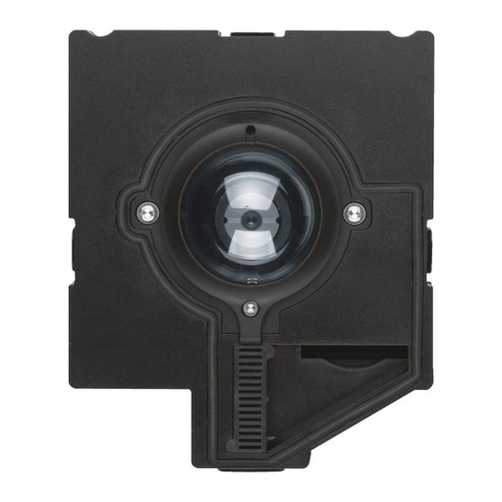
Figure 1: Front video module
01
(1)
z
(2)
Figure 2: Front video insert
(1) Microphone
(2) Locating screw for camera (Allen key supplied)
(3) Twilight sensor for call button
(4) Camera
(5) Loudspeaker openings
(6) Module carrier (according to reference)
(7) Centre plate (only with video modules)
(8)
(9)
(10)
(11)
Figure 3: Back
(8) Adjustment button Upwards
(9) 7-segment display
(10) Selection button
(11) Adjustment button downwards
(12) Connection for module connecting cable
(13) Connection terminal block
Function
The device works in the 2-wire bus system and
enables communication via sound and image.
Correct use
- for surface-mounted, flush-mounted or built-in
installation
- Not compatible with intercom systems of other
manufacturers
- suitable for use exterior applications
Product characteristics
- One-man commissioning
- expandable for modules, e.g. call push-button
- Call push-button acknowledge tone (can be
switched off)
- Call button, light release or door release can be
adjusted even without any function
- Switch-on brightness level of the call button
backlighting adjustable
- Colour camera
- invisible, glare-free IR LED night lighting
- temperature controlled camera heating for clear
view
- scratch-proof camera cover
- Loudspeaker and microphone protected against
sabotage
- Volume and microphone sensitivity settable
- Door release contact on 1 ... 10 s adjustable
- Door release without previous call adjustable in
single door systems
Operation of call push-buttons
Call push-buttons are connected to the device.
Establish call (ringing)
z Press the call push-button assigned to the
desired subscriber.
If configured, the call push-button activation is
(6)
(7)
confirmed by an acknowledge tone. Addressed
indoor stations are called.
(3)
(4)
(5)
(12)
(13)
Switch-on lights
A call push-button is configured and labelled for
lighting control.
z Press the call push-button for lighting.
If configured, the call push-button activation is
confirmed by an acknowledge tone. The light
contact of a line power supply is closed for the
set time.
Label call push-button
z Keep call push-button pressed on one side.
On the opposite side, the lever opening (14) is
accessible for a screwdriver.
z Position the screwdriver in the lever opening
(14) and release the interlock (Figure 4).
z Remove cover with name plate insert.
Figure 4: Removing name plate cover
(14) Lever opening
z Label name plate insert if required.
z Insert name plate insert, prepared foil or prepa-
red labelling strip into the cover.
z Press on cover.
Do not use any paper for the name plate insert,
P
since moisture and UV light will damage the
paper and labelling.
UV-resistant foil with laser printing is suitable
P
for labelling as well as labelling devices for
labelling strip:
- small buttons - 12 mm
- medium buttons - 30 mm
Detailed labelling references are to be foun on
our homepage.
Door stations with status indication
Dis-
Cause
Function/Lighting
play
duration
A subscriber is
After 90 s without call
called.
acceptance or an operati-
on on the door station,
goes out.
A subscriber
goes out,
accepts the
long as the intercom con-
door call.
nection is pressed down,
max. 3 min.
The door is
Call not accepted:
unlocked.
Symbol goes out and
lights up for the unlok-
king time set on the door
station.
Call accepted:
In addition to the , the
lights up for the unlok-
king time set on the door
station.
5 sec after the
Table 1: Status indications of door station
(14)
lights up as
goes out approx.
symbol.
Advertisement

Subscribe to Our Youtube Channel
Related Manuals for hager RE 510 Series


Summary of Contents for hager RE 510 Series
- Page 1 Switch-on lights A call push-button is configured and labelled for lighting control. z Press the call push-button for lighting. If configured, the call push-button activation is confirmed by an acknowledge tone. The light contact of a line power supply is closed for the set time.
- Page 2 Information for electricians The door release lead must not be inserted If interference occurs in telecommunications through the door station in order to protect systems, radio services or other systems during Installation and electrical connection against manipulation. the operation of existing video door communication systems, measures for shielding and earthing the z For call push-button backlighting and camera DANGER!
- Page 3 Set individual call push-button address/function Display saved error codes Error Error cause Counter actions The menu entry Set individual call push-button Device errors that occur during operation are code address/function is selected and flashes. stored in the the error memory of the device for Communication error If the error per- diagnosis.
- Page 4 Lever up the interlocking cover strips (16) at the top and bottom using the screwdriver and remove (Figure 15). Figure 17: Unlatching module T +49 6333 992 0 F +49 6333 992 7666 info@hager.com hager.com - 03.2023...
Need help?
Do you have a question about the RE 510 Series and is the answer not in the manual?
Questions and answers