
Related Manuals for Ideal Heating LOGIC AIR 8


Summary of Contents for Ideal Heating LOGIC AIR 8
- Page 1 U0753484_2451_EN_1 24/05/2023 MAINTENANCE MANUAL LOGIC AIR 8-10 Air/water heat pump Monobloc system To be safety stored by the user for reference by installers.
-
Page 3: Table Of Contents
Front panel removal ..... . 60 Precautions for exchange of refrigerant-cycle-parts . . .70 LOGIC AIR 8-10 / Maintenance Manual / 2451 - EN - 3 -... -
Page 4: Presentation
150 mm 1500 mm 200 mm 3000 mm 300 mm 3500 mm 400 mm M = 300 mm Max 500 mm N = 500 mm Max 600 mm - 4 - LOGIC AIR 8-10 / Maintenance Manual / 2451 - EN... -
Page 5: Basic Hydronic Layout
EP - Refrigerant to Water Heat Exchanger STC - Compressor temp. sensor F - Filter STE - Oudoor temp. sensor Ma - Manometer STEC - Discharge temp. sensor LOGIC AIR 8-10 / Maintenance Manual / 2451 - EN - 5 -... -
Page 6: Electrical Connection
(Connexion UE/UI) Permanent Alimentation power supply permanente Tightening torque Nm (kgf.cm) M4 screw 1.2 to 1.8 (12 to 18) M5 screw 2.0 to 3.0 (20 to 30) - 6 - LOGIC AIR 8-10 / Maintenance Manual / 2451 - EN... -
Page 7: Electrical Wiring
► Electrical wiring LOGIC AIR 8-10 / Maintenance Manual / 2451 - EN - 7 -... -
Page 8: Heat Pump Error Code
Circulation pump error x 10 Discharge temp. error x 10 Compressor temp. error x 10 Low pressure error x 10 x 14 Low water fl ow error - 8 - LOGIC AIR 8-10 / Maintenance Manual / 2451 - EN... -
Page 9: Flashing Of The Diodes Visible On The Main Board In The Outdoor Unit
● x 10 x 11 Ο Ο ● ● Heat sink temp. error ● x 10 x 14 Ο Ο Ο ● Low water fl ow error LOGIC AIR 8-10 / Maintenance Manual / 2451 - EN - 9 -... -
Page 10: Outdoor Unit Clearing
>> If Outdoor fan motor is abnormal, replace Outdoor unit fan motor and Main PCB. >> If Outdoor fan motor is normal, replace Main PCB. BLACK WHITE BLACK WHITE - 10 - LOGIC AIR 8-10 / Maintenance Manual / 2451 - EN... - Page 11 >> Check if indicated value swings berween AC30v and AC130V at outdoor unit terminal 2 - 3. >> If it is abnormal, replace Controller PCB. BLACK WHITE BLACK WHITE LOGIC AIR 8-10 / Maintenance Manual / 2451 - EN - 11 -...
- Page 12 >> If abnormal condition is found, correct it. Check Point 2 : Replace Main PCB If Check Point 1 do not improve the symptom, replace Main PCB of outdoor unit. - 12 - LOGIC AIR 8-10 / Maintenance Manual / 2451 - EN...
- Page 13 Check if temporary voltage drop was not generated. Change Main PCB. Check if momentary open was not generated. Check if ground is connection correctly or there are no related cables near the power line. LOGIC AIR 8-10 / Maintenance Manual / 2451 - EN - 13 -...
- Page 14 Check Point 3 : Replace Inverter PCB Replace Outdoor unit Inverter PCB. Check Point 4 : Replace Main PCB If Check Point 1~3 do not improve the symptom. Change Main PCB. - 14 - LOGIC AIR 8-10 / Maintenance Manual / 2451 - EN...
- Page 15 Outdoor unit Inverter PCB while the compressor stops. Forecast of cause: 1. Outdoor unit Inverter PCB failure Check Point 1 : Replace Inverter PCB Replace Outdoor unit Inverter PCB. LOGIC AIR 8-10 / Maintenance Manual / 2451 - EN - 15 -...
- Page 16 Main PCB P15 :3-4 voltage value =5V Remove the thermistor from Main PCB, check the voltage. If the voltage does not appear, replace Main PCB and execute the check operation again. - 16 - LOGIC AIR 8-10 / Maintenance Manual / 2451 - EN...
- Page 17 Main PCB P10 :1-3 voltage value =5V Remove the thermistor from Main PCB, check the voltage. If the voltage does not appear, replace Main PCB and execute the check operation again. LOGIC AIR 8-10 / Maintenance Manual / 2451 - EN - 17 -...
- Page 18 Main PCB P15 :1-2 voltage value = Remove the thermistor from Main PCB, check the voltage. If the voltage does not appear, replace Main PCB and execute the check operation again. - 18 - LOGIC AIR 8-10 / Maintenance Manual / 2451 - EN...
- Page 19 Main PCB P5 :1-3 voltage value =5V Remove the thermistor from Main PCB, check the voltage. If the voltage does not appear, replace Main PCB and execute the check operation again. LOGIC AIR 8-10 / Maintenance Manual / 2451 - EN - 19 -...
- Page 20 Remove the thermistor from Inverter PCB, check the voltage 1 2 3 1 2 3 P700 If the voltage do not appear, replace Inverter PCB and execute the check operation again. - 20 - LOGIC AIR 8-10 / Maintenance Manual / 2451 - EN...
- Page 21 1 2 3 4 5 6 Expansion valve temperature thermistor (PA1: 4-6) If the voltage do not appear, replace Main PCB, and excecute the check operation again. LOGIC AIR 8-10 / Maintenance Manual / 2451 - EN - 21 -...
- Page 22 Remove the thermistor from Supply PCB, check the voltage 1 2 3 1 2 3 If the voltage do not appear, replace Supply PCB and execute the check operation again. - 22 - LOGIC AIR 8-10 / Maintenance Manual / 2451 - EN...
- Page 23 Check the complete insulation of grounding. Check Point 3 : Replace Inverter PCB If Check Point 1, 2 do not improve the symptom, change Inverter PCB. LOGIC AIR 8-10 / Maintenance Manual / 2451 - EN - 23 -...
- Page 24 Change Inverter PCB, and execute the check operation again. Type of contact Characteristics of pressure switch (P770) Pressure switch 4.2 0.1MPa Contact : Short Open Pressure Contact : Open Short 3.2 0.15MPa - 24 - LOGIC AIR 8-10 / Maintenance Manual / 2451 - EN...
- Page 25 >> 2pin (White) - 3pin (Black) Voltage is refer to the following graph. Voltage (V) Pressure (MPa) I I f the voltage is not correct, replace Pressure sensor. LOGIC AIR 8-10 / Maintenance Manual / 2451 - EN - 25 -...
- Page 26 If Check Point 1, 2 do not improve the symptom, change Main PCB. Check Point 4: Replace Compressor If Check Point 3 do not improve the symptom, change Compressor. - 26 - LOGIC AIR 8-10 / Maintenance Manual / 2451 - EN...
- Page 27 If Check Point 3 do not improve the symptom, change Main PCB. Check Point 5: Replace Compressor If Check Point 3 do not improve the symptom, change Compressor. LOGIC AIR 8-10 / Maintenance Manual / 2451 - EN - 27 -...
- Page 28 If the voltage is not correct, replace Inverter PCB. Check Point 5 : Replace Main PCB If Check Pint 1~4 do not improvethe symptom, replace Main PCB. - 28 - LOGIC AIR 8-10 / Maintenance Manual / 2451 - EN...
- Page 29 Check if the pump is blocked, and correctly supplied between PCB and Pump else >>Replace the condenser circulation pump. Check Point 2 : If error is still displayed after restarting >>Replace ODUM Hydraulic PCB and Main PCB . LOGIC AIR 8-10 / Maintenance Manual / 2451 - EN - 29 -...
- Page 30 Check Point 4 : Check the discharge temp. thermistor Discharger temp. thermistor characteristics check (Check by disconnecting thermistor from PCB. Refer to the Troubleshooting 9) Check Point 5 : Check the refrigerant amount Leak check - 30 - LOGIC AIR 8-10 / Maintenance Manual / 2451 - EN...
- Page 31 Check Point 4 : Check the compressor temp. thermistor Compressor temp. thermistor characteristics check (Check by disconnecting thermistor from PCB. Refer to the Troubleshooting 9) Check Point 5 : Check the refrigerant amount Leak check LOGIC AIR 8-10 / Maintenance Manual / 2451 - EN - 31 -...
- Page 32 Check Point 6 : Check the suction pressure sensor Suction pressure sensor characteristics check (Characteristics of Suction pressure sensor, ) Check Point 7 : Check the refrigerant amount Leak check - 32 - LOGIC AIR 8-10 / Maintenance Manual / 2451 - EN...
- Page 33 Check Point 3 : Check the Heatsink temperature thermistor Heatsink temperature thermistor characteristics check (Check by disconnecting thermistor from PCB) Refer to the Troubleshooting 11 Check Point 2 : Replace Inverter PCB Replace Inverter PCB LOGIC AIR 8-10 / Maintenance Manual / 2451 - EN - 33 -...
- Page 34 -> Replace the the flow rate sensor Else replace the condenser circulation pump. If error is still displayed -> Replace ODUM Hydraulic PCB and Main PCB - 34 - LOGIC AIR 8-10 / Maintenance Manual / 2451 - EN...
- Page 35 >> If Fuse is open, check if the wiring between Terminal and Main PCB is loose, and replace Fuse. If the symptom does not change by above Check 3, replace Main PCB. LOGIC AIR 8-10 / Maintenance Manual / 2451 - EN - 35 -...
- Page 36 (Neon bulb or electric equipment that may cause harmonic wave) Check the complete insulation of grounding. >> If the symptom dose not change by above check 1,2 replace main PCB of outdoor unit. - 36 - LOGIC AIR 8-10 / Maintenance Manual / 2451 - EN...
- Page 37 Is there any objet which obstruct the fan rotation ? Check if vibration noise by loose bolt or contact noise of piping is happening Is Compressor looked ? >> Check Compressor (Outdoor Unit error code) LOGIC AIR 8-10 / Maintenance Manual / 2451 - EN - 37 -...
-
Page 38: Service Parts Information
(Refer to the next page). >> If there is no failure, the defect of Compressor can be considered. (Compression part broken or valve defective.) Replace Compressor - 38 - LOGIC AIR 8-10 / Maintenance Manual / 2451 - EN... - Page 39 Compressor. Resistance Value : % at 20°C Check Point 3 : Replace Main PCB If the symptom does not change with above Check 1, 2, replace Main PCB. LOGIC AIR 8-10 / Maintenance Manual / 2451 - EN - 39 -...
- Page 40 , there is a possibility of inside clogged. In this case, replace Strainer. Pipe (In) Pipe (Out) Pipe (In) Pipe (Out) - 40 - LOGIC AIR 8-10 / Maintenance Manual / 2451 - EN...
- Page 41 (wire color) 1 (Red) DC voltage (Vm) No function No function 4 (Black) 5 (White) Control voltage (Vcc) 6 (Yellow) Speed command (Vsp) 7 (Brown) Feed back (FG) LOGIC AIR 8-10 / Maintenance Manual / 2451 - EN - 41 -...
- Page 42 102,5 20,6 64,2 12,6 41,3 27,3 18,4 12,7 Applicable Discharge temp. Heat exchanger. Outdoor temp. Heatsink temp. water temp. TH Thermistors Compressor temp. TH Ex. valve temp. - 42 - LOGIC AIR 8-10 / Maintenance Manual / 2451 - EN...
-
Page 43: Operating Limits
** Acoustic power level @standard rating cond. (EN 14511-2) A7W55 outdoor unit. *** When the outdoor temperature continuously exceeds 35°C, DHW heating is done by the water heater heating element. LOGIC AIR 8-10 / Maintenance Manual / 2451 - EN - 43 -... -
Page 45: Failures
fl oor fl ow/ return temps responsibility into question Service station high return temp (infrared thermometer) *Not required and not shown on the device. LOGIC AIR 8-10 / Maintenance Manual / 2451 - EN - 45 -... - Page 46 Disconnect the compressor relay and the condenser connection. Measure the resistance value at the points shown on the illustration, and then compare the values observed with those in the table. Single phase type Multimeter Resistor 1 MOhm or more Main PCB - 46 - LOGIC AIR 8-10 / Maintenance Manual / 2451 - EN...
- Page 47 4-way valve switching ? Servicing complete Valve coil faulty ? Expansion correct ? Change Change coil expansion valve Inspect refrigeration Change 4-way valve lines (clogging) after testing LOGIC AIR 8-10 / Maintenance Manual / 2451 - EN - 47 -...
- Page 48 Too : Heat exchanger temperature Defrost Too(n-1) : Too value of 5min ago Too10 : Too value at 10 min later from operation start OT : Outdoor temperature - 48 - LOGIC AIR 8-10 / Maintenance Manual / 2451 - EN...
-
Page 49: Compressor Operating Checks
• Move the sensor between the exchanger blades to a place where the exchanger is iced up. • If all these points have been checked, replace the outdoor controller board. LOGIC AIR 8-10 / Maintenance Manual / 2451 - EN - 49 -... -
Page 50: Pump Down Process
3-way valves. Wait 3 minutes, turn the power on and perform a • If an error occurs, recover the refrigerant from service port. Sign “ - 50 - LOGIC AIR 8-10 / Maintenance Manual / 2451 - EN... -
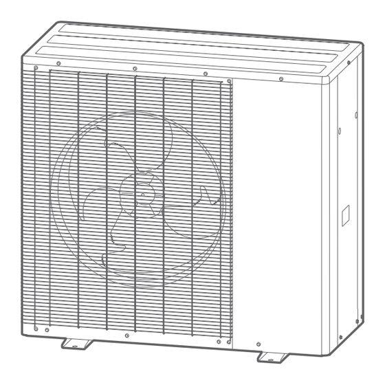
Page 52: Disassembly Process Of Outdoor Unit
Disassembly Process of Outdoor Unit ► Appareance 1095 Accessories Elbow Plug (x9) - 52 - LOGIC AIR 8-10 / Maintenance Manual / 2451 - EN... - Page 53 16. Drain valve (V) 5. Air to Refrigerant Heat Exchanger (Ech) 11. Schrader Valve 17. Automatic bleeder valve (PgA) 6. Supply terminal 12. High pressure switch (Prt) 18. Flowmeter (Db) LOGIC AIR 8-10 / Maintenance Manual / 2451 - EN - 53 -...
-
Page 54: Right Service Panel Removal
► Right service panel removal Unscrew the 5 screws. ► Top panel removal Unscrew the 4 screws. Unscrew the 7 screws. - 54 - LOGIC AIR 8-10 / Maintenance Manual / 2451 - EN... -
Page 55: Front Service Panel And Rear Panel Removal
► Front service panel and rear panel removal Unscrew the 4 screws. Unscrew the 8 screws. LOGIC AIR 8-10 / Maintenance Manual / 2451 - EN - 55 -... -
Page 56: Main Pcb Removal
► Main PCB removal Unscrew the 4 screws. Remove the connectors and the wires. Press the 4 locking spacers to remove the PCB. - 56 - LOGIC AIR 8-10 / Maintenance Manual / 2451 - EN... -
Page 57: Inv Pcb Removal
Place the hook in front of the triangle mark. Remove the 3 connectors. Unscrew the screw. Remove all connectors and wires. Press the 4 locking spacers to remove the inverted PCB. LOGIC AIR 8-10 / Maintenance Manual / 2451 - EN - 57 -... -
Page 58: Hydronic Circuit Pcb Removal
Remove the connectors and wires. Press the 4 locking spacers to remove the hydronic circuit PCB. ► Control box unit removal Unscrew the 5 screws. Unscrew the 2 screws. - 58 - LOGIC AIR 8-10 / Maintenance Manual / 2451 - EN... - Page 59 Unscrew the 2 screws. Remove the binders. LOGIC AIR 8-10 / Maintenance Manual / 2451 - EN - 59 -...
-
Page 60: Front Panel Removal
► Front panel removal Unscrew the 9 screws. - 60 - LOGIC AIR 8-10 / Maintenance Manual / 2451 - EN... -
Page 61: Fan Motor Removal
Fan motor removal Remove the fan nut and the fan propeller. Cut the binders. Loose the clamps to remove the fan motor lead wire. Unscrew the mounting screws. LOGIC AIR 8-10 / Maintenance Manual / 2451 - EN - 61 -... -
Page 62: Thermistor Removal
Cut the binders to remove the isolation. Push the hook to remove the thermistor (outdoor temperature). Remove the thermistor (EEV). ► 4-way valve coil removal Unscrew the mounting screw. Remove the solenoid coil. - 62 - LOGIC AIR 8-10 / Maintenance Manual / 2451 - EN... -
Page 63: Expansion Valve Coil Removal
► Expansion valve coil removal ► Pressure switch removal LOGIC AIR 8-10 / Maintenance Manual / 2451 - EN - 63 -... -
Page 64: Compressor Removal
► Compressor removal Unscrew the 9 screws. - 64 - LOGIC AIR 8-10 / Maintenance Manual / 2451 - EN... - Page 65 Cut the discharge pipe and the suction pipe in this range. LOGIC AIR 8-10 / Maintenance Manual / 2451 - EN - 65 -...
-
Page 66: Circulation Pump Removal
► Circulation pump removal - 66 - LOGIC AIR 8-10 / Maintenance Manual / 2451 - EN... -
Page 67: Flowmeter Removal
► Flowmeter removal LOGIC AIR 8-10 / Maintenance Manual / 2451 - EN - 67 -... -
Page 70: Precautions For Exchange Of Refrigerant-Cycle-Parts
Tighten the fl are part gripping it (Tightening torque:12 1.5N m). PRESSURE SWITCH 100°C Do the static electricity measures. 3-WAY VALVE (GAS) 120°C 3-WAY VALVE (LIQUID) 120°C - 70 - LOGIC AIR 8-10 / Maintenance Manual / 2451 - EN... - Page 72 are in conformity with the relevant Union harmonized directives and regulations: are in conformity with the requirements of the relevant UK legislation: - Low Voltage Directive (LVD) - 2014/35/EU - Electrical Equipment (Safety) Regulations 2016 - S.I. 2016 No. 1101 - Machinery Directive - 2006/42/EC - Supply of Machinery (Safety) Regulations 2008 - S.I.
Need help?
Do you have a question about the LOGIC AIR 8 and is the answer not in the manual?
Questions and answers