Table of Contents
Advertisement
Quick Links
INSTALLATION AND
SERVICING
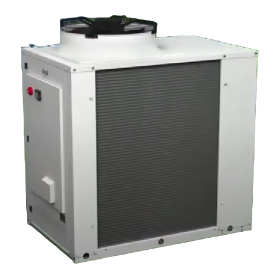
ECOMOD AHP60
50 and 70 kW
Air/water monobloc heat pump
When replacing any part on this appliance, use only spare parts that you can be assured conform to the safety and performance
specification that we require. Do not use reconditioned or copy parts that have not been clearly authorised by Ideal.
For the very latest copy of literature for specification and maintenance practices visit our website www.idealcommercialboilers.com
where you can download the relevant information in PDF format.
September 2022
UIN 00U07352260-A
Advertisement
Table of Contents

Subscribe to Our Youtube Channel
Related Manuals for Ideal Heating ECOMOD AHP60 50 kW


Summary of Contents for Ideal Heating ECOMOD AHP60 50 kW
- Page 1 INSTALLATION AND SERVICING ECOMOD AHP60 50 and 70 kW Air/water monobloc heat pump When replacing any part on this appliance, use only spare parts that you can be assured conform to the safety and performance specification that we require. Do not use reconditioned or copy parts that have not been clearly authorised by Ideal. For the very latest copy of literature for specification and maintenance practices visit our website www.idealcommercialboilers.com where you can download the relevant information in PDF format.
-
Page 3: Table Of Contents
AHP60-50/70 - Installation, Use and Maintenance CONTENTS 1. REGULATIONS, RECOMMENDATIONS AND WARNINGS ..............5 1.1. Applicable regulations and standards ......................5 1.2. Recommendations and warnings ......................... 5 2. DESCRIPTION OF THE EQUIPMENT ................15 2.1. Designations and scope ..........................15 2.2. Packaging ..............................15 2.3. Definitions .............................. - Page 4 7.5. Cleaning the external surfaces ........................65 7.6. Maintenance of the outdoor unit ........................65 7.7. Residual safety risks ........................... 66 7.8. Heavy maintenance work ..........................67 7.9. “Maintenance” check list ..........................68 8. END OF PRODUCT LIFE- ....................74 DATA FOR PRODUCTS ≤ 70KW ............76 9.
-
Page 5: Regulations, Recommendations And Warnings
1. REGULATIONS, RECOMMENDATIONS AND WARNINGS 1.1. Applicable regulations and standards This outdoor heat pump has been designed in accordance with current regulations and must be used accordingly. See the list of standards on the back cover. This device must be transported in compliance with the Local Laws. This device and its refrigerant R32 must be handled in compliance with the application orders of the F Gas regulations. Specific guidelines related to the presence of Fluorine in the composition of the R32 fluid are specified in the European Union regulation n°... - Page 6 The elements indicated below are not exhaustive given the diversity of the possible installations and interventions; they cannot be considered as an undertaking as to the responsibility of the Ideal Heating. These elements cannot replace a risk analysis, which remains the responsibility of the installer and the personnel working on the machines.
- Page 7 MEASURES IN THE EVENT OF AN ACCIDENTAL LEAK Use personal protection equipment. Evacuate the personnel to safe areas. Individual precautions: Eliminate ignition sources. Ensure there is adequate ventilation. Environmental precautions: Try to stop the leak. Cleaning methods: Ventilate the area. HANDLING AND STORAGE Handling: Ensure that the premises have adequate air renewal/extraction .
- Page 8 TOXICOLOGICAL INFORMATION High toxicity: LD/LC50/inhalation/4 hours/rat test = 1107000 mg/m3. Local effects: No known effects. Long term toxicity: No known effects. ENVIRONMENTAL INFORMATION Global warming potential GWP (R744=1): Ozone damage potential (R11=1): Of the ozone ODP (R11=1): Comply with the supplier’s gas collection programme. Avoid direct Disposal Considerations: emission into the atmosphere. ■ Specific warnings on the R32 refrigerant The R32 refrigerant: - is odourless;...
- Page 9 at least 80% of the wall (or the equivalent if more than one wall is open to the outside air), is considered to be open to the outside air. It must be located so that no refrigerant leaks can enter the building and/or endanger people and property.
- Page 10 Percentage of Efficiency cor- Absorbed power Water flow rate Loss of head cor- Freezing point [°C] glycol rection factor correction factor correction factor rection factor -3.2 0.985 1.02 1.08 -7.8 0.98 0.99 1.05 1.12 -14.1 0.97 0.98 1.10 1.22 -22.3 0.965 0.97 1.14...
- Page 11 TO THE EXPANSION SYSTEM Example of recommended connection diagram (non exhaustive) 01.07.2022 11 / 78...
- Page 12 1.2.5. General safety rules Before starting any operation on the units, each operator must be fully familiar with the operation of the machine and its controls and have read and understood all the information contained in this manual. The removal and/or handling of any safety device is strictly prohibited. Children and unaccompanied disabled people are not allowed to use the device.
- Page 13 Be sure to maintain a posture that does not cause fatigue when installing and maintaining the unit. Also check the weight of any component before handling it. The unit works with the refrigerant R32, included in the list of greenhouse gases (GWP 675) that meet the requirements of EU Regulation No.
- Page 14 AHP60-50/70 - Installation, Use and Maintenance 14 / 78 00U07352260-A_EN...
-
Page 15: Description Of The Equipment
2. DESCRIPTION OF THE EQUIPMENT 2.1. Designations and scope ECOMOD AHP60: Heat pump comprising a close-coupled heat pump Hot water production system for heating networks or thermodynamic production of domestic hot water. 2.2. Packaging Outdoor unit Model Code ECOMOD 50 AH090921 ECOMOD 70 AH090924... -
Page 16: Technical Data
AHP60-50/70 - Installation, Use and Maintenance 2.4. Technical data 2.4.1. Data sheet for standard units This product is designed to be installed at a maximum altitude of 2000m AHP 60 Measurement TECHNICAL CHARACTERISTICS units 50 kW 70 kW Heat output (1) 24.1 / 50.2 32.9 / 66.8 min./nom. - Page 17 AHP60-50/70 - Installation, Use and Maintenance AHP 60 Measurement TECHNICAL CHARACTERISTICS units 50 kW 70 kW Hydraulic circuit water capacity Max. pressure on water side Hydraulic connections Ø 1 1/2” (DN 40) Hydraulic Minimum volume of water for bottle circuit Maximum power of circulator 1.04 1.35...
- Page 18 AHP60-50/70 - Installation, Use and Maintenance 2.4.2. 2.4.2. Electrical data for the unit and auxiliaries Electrical data for the unit and auxiliaries Unit power supply Remote control circuit V/~/Hz 3N~400V-50Hz* V/~/Hz 12/01/1950 Integrated control circuit Power supply to fans V/~/Hz 12/01/1950 V/~/Hz 3N~400V-50Hz*...
- Page 19 AHP60-50/70 - Installation, Use and Maintenance 2.4.3.2. Partial load Sound levels refer to units at full load and in conditions guaranteeing a thermal capacity equal to that declared at a temperature of 7°C for an average climate, in accordance with standard EN 14825, in accordance with the provisions of EU regulation 813/2013(dry bulb temperature (wet bulb temperature) of the outside air = 7°C (6°C), water temperature inlet-outlet = 47-55°C). The tolerance on the value of the total sound power level is of 2dB(A).
-
Page 20: Description
AHP60-50/70 - Installation, Use and Maintenance 2.5. Description 2.5.1. Models AHP60 50 - 70 kW Sor�e d’eau Entrée d’eau 1754 1110 1920 Left hand side view Right hand side view Front view Figure 1 - Dimensions of the models AHP60 50 - 70 kW Dimensions and weight Models AHP60 50 kW... - Page 21 AHP60-50/70 - Installation, Use and Maintenance In case of maintenance and/or inspection of the compressors, it is necessary to access the inside of the unit by opening the door located on the front side, where the electrical panel is also located. To unlock it, it is necessary to unscrew the fixing screws using a suitable tool and pull it towards you using the handle under the panel.
-
Page 22: Operating Principle
AHP60-50/70 - Installation, Use and Maintenance 2.6. Operating principle 2.6.1. Production of domestic hot water or heating When the heat pump is operating, other than in the start-up and transition phases, the inlet temperature must not fall below 25°C. A lower value may cause system anomalies, including damage to the compressor. Similarly, the outlet temperature must not exceed 58°C. With temperatures outside of this range, especially if combined with low water flow rates, there may be anomalies in the operation of the unit, or in the most critical cases, the safety devices may be... - Page 23 AHP60-50/70 - Installation, Use and Maintenance Water flow rate on the condenser The nominal water flow rate is determined for a temperature difference of 5°C between the inlet and the outlet of the condenser. The maximum authorised flow rate is that with a temperature difference of 3°C whereas the minimum is that with a temperature difference of 8°C in nominal conditions, as shown on the data sheet. For more detailed information, we provide a table below which indicates the minimum flow rates to be guaranteed on the condenser to ensure that it operates correctly according to the model, as well as the disconnection and re-engagement flow rates for the flow rate controller.
-
Page 24: Installation
AHP60-50/70 - Installation, Use and Maintenance 3. INSTALLATION The outdoor unit and the Ecomod Heat Control control unit must be installed CAUTION: using the new equipment supplied. 3.1. Lifting and handling Handling must be carried out by qualified personnel, correctly equipped with tools suited to the weight and size of the unit, in compliance with the accident prevention safety rules. Notes: 1. -
Page 25: Installation
AHP60-50/70 - Installation, Use and Maintenance 3.2. Installation The choice of the position for installation is particularly important insofar as any later movement is a delicate operation requiring the intervention of a qualified person. Comply with the maximum and minimum distances for the outdoor unit, the performance and service life guarantees depend on this. 3.3. - Page 26 AHP60-50/70 - Installation, Use and Maintenance • The outdoor unit is weatherproof, but avoid installing it in a place where it may be exposed to dirt or heavy water run-off (under a leaking gutter, under a roof, etc.). Avoid installing the unit in places where water is likely to stagnate or fall, for example from gutters. Also avoid places where snow can build up (e.g.
- Page 27 AHP60-50/70 - Installation, Use and Maintenance Industries / risk zones Incinerators Agriculture Paper / Salt Swimming Treatment Type Corrosive product & other Cleaning & fertiliser wood extraction pools plants combustions manufacturers Nitrogen oxides (NOX) Sulphur oxides Oxides (SxOy) Carbon oxides Sulphurs Hydrogen fluoride Volatile gases...
- Page 28 AHP60-50/70 - Installation, Use and Maintenance 3.3.2. Installation precautions We recommend that you carry out a noise nuisance risk study. This will have to take into account the residual noise without the heat pump, the data of the machine, the implatation zone, the distance to the measurement point, this list is not exhaustive. The day and night normative noise level requirements are distinct.
- Page 29 AHP60-50/70 - Installation, Use and Maintenance 3.3.3. Minimum technical clearances • By following the installation precautions, it is absolutely essential to ensure the following minimum service clearances are respected. • Therefore, avoid placing the appliance under canopies or near plants or walls to avoid air recirculation.
- Page 30 • The ducted installation must be carried out according to the configurations shown in the diagram in the previous figure, with a maximum loss of head due to the ducts of: • In the event of failure to comply with these precautions, the performance of the heat pump may be severely degraded and the Ideal Heating shall not be held liable. 30 / 78 00U07352260-A_EN...
- Page 31 AHP60-50/70 - Installation, Use and Maintenance • These minimum clearances must be respected regardless of the installation to guarantee the performances and safety of the unit. • Generally, any possibility of air recirculation should be avoided, as this will degrade the performance of the machine.
-
Page 32: Installing The Control Unit
AHP60-50/70 - Installation, Use and Maintenance 3.4. Installing the control unit The Ecomod Heat Control control unit for the heat pump is supplied separately, with a specific installation guide inside its packaging. Refer to this guide to connect this unit. 3.5. Position of the centre of gravity and the vibration shock absorbers The position of the centre of gravity of each heat pump is indicated in the table, with reference to the dimensions indicated in the image. -
Page 33: Hydraulic Connections
AHP60-50/70 - Installation, Use and Maintenance Models A [mm] B [mm] C [mm] D [mm] ECOMOD AHP60 1410 50 kW and 70 kW 3.6. Hydraulic connections 3.6.1. The accessories to be connected to the AHP60 hydraulic station - The hydraulic connections must comply with good engineering practices according to the regulations in force. - Page 34 AHP60-50/70 - Installation, Use and Maintenance A metal filter must be fitted (with a mesh size not exceeding 1000 microns) as well as a T connector on the return pipe of the system labelled WATER INLET. If the flow rate switch is tampered with or modified, or if the metal filter and filter- settler are not fitted to the system, the warranty is immediately void.
- Page 35 The adjustment and management of flow rates is the responsibility of the installer/ under installer/operator responsibility and will not be operated by CAUTION: Ideal Heating. During commissioning of the system, balancing control will be requested by Ideal Heating. Without control, commissioning will be refused.
- Page 36 AHP60-50/70 - Installation, Use and Maintenance refreshing the oxygen through significant contributions of water, the unit might not experience any damage whatsoever. However, it is important to follow the sizing rules and installation guidelines in order to prevent oxygen from continuously flowing into the heating water. From these rules, we have: Preferably an expansion vessel with a membrane rather than an open expansion vessel that allows direct passage.- Internal pressure with the unit of more than 1 bar cold.
- Page 37 AHP60-50/70 - Installation, Use and Maintenance 3.6.6. Connecting water supply Check that the system is stopped, with the general switch in position 0. Add water until the pressure of the hydraulic circuit reaches 2 bar. The P drain valve is an automatic drainer, run the pump to readjust the pressure.
- Page 38 AHP60-50/70 - Installation, Use and Maintenance 3.6.6.1. Precautions to take for water filling • Supervise all filling/refilling operations. • Before filling/refilling the system with water, disconnect the power supply to the units. • Filling/refilling the installation must always be carried out under controlled pressure conditions (max. 1 bar). Ensure that a pressure reducer and a safety valve have been fitted on the filling/ refilling duct. • The water in the filling/refilling duct must be filtered properly beforehand to remove all impurities and suspended particles. Ensure that a removable screen filter and filter-settler are installed. • Periodically check and evacuate the air that accumulates in the system. • Fit an automatic air vent at the highest point of the system. To fill the installation, we recommend the use an external tap installed by the installer.
-
Page 39: Electrical Connections
AHP60-50/70 - Installation, Use and Maintenance The air vent is delivered closed from the factory. It must be opened so that it can CAUTION: evacuate the air. . If there is a water leak, the component must be changed, by unscrewing it INFORMATION: with two wrenches, as shown in the picture below. - Page 40 AHP60-50/70 - Installation, Use and Maintenance 3.7.1. General remarks on electrical connections Check that the electrical power supply complies with the nominal characteristics of the appliance (voltage, phases, frequency) as stated on the data plate located on the side panel of the appliance. The electrical connection must comply with the electrical wiring diagram of the appliance and local and international regulations (fit a main circuit breaker, and differential circuit breakers for each line, and earth installation adequately, etc.).
- Page 41 AHP60-50/70 - Installation, Use and Maintenance All of the installation operations must be carried out when the heat pump is stopped, and after disconnecting the electrical power supply. These operations must only be carried out by QUALIFIED PERSONNEL. CAUTION: Remove the cover without removing the cable duct support plate. When the work is complete, refit all of the covers removed with their screws and seals (if present).
- Page 42 AHP60-50/70 - Installation, Use and Maintenance 3.7.4. Connecting the control unit See Ecomod Heat Control manual 3.7.5. User terminal The terminal block is located inside the electrical panel. For access, see the instructions. The terminal block must be connected in accordance with the information below. The connections shown below are standard.
- Page 43 AHP60-50/70 - Installation, Use and Maintenance Terminal Connection Type input 3-Ph/N/PE, 400 Power supply Connect the earth wire VAC, 50Hz input 3-Ph/N/PE, 400 Power supply connect the neutral wire from the network VAC, 50Hz input 3-Ph/N/PE, 400 Power supply Connect the L1 phase wire from the main power supply VAC, 50Hz input 3-Ph/N/PE, 400 Power supply...
-
Page 44: Pre-Requisites Before Commissioning
AHP60-50/70 - Installation, Use and Maintenance 4. PRE-REQUISITES BEFORE COMMISSIONING 4.1. Verification before switching on • Check that the electrical and hydraulic diagrams of the installation the machine is connect- ed to are available. • Ensure that the isolation valves of the hydraulic circuits are open. • Check that there are safety valves filters and expansion systems. -
Page 45: Switching On
- Check if heating cables of the compressors are powered correctly. 4.3. Commissioning - The heat pump must only be commissioned by the Ideal Heating commissioning personnel. - If heating is required before the planned commissioning date, back-up generators may be used:... -
Page 46: Operating Diagram
AHP60-50/70 - Installation, Use and Maintenance 4.5. Operating diagram 4.5.1. AHP60 50-70 kW See water diagram on page 37 Figure 15 - Operating diagram • Thicker lines represent insulated ducts 46 / 78 00U07352260-A_EN... - Page 47 AHP60-50/70 - Installation, Use and Maintenance INVC COMPRESSOR BY-PASS LINE FOR COOLING EVAPORATOR MANUAL BALL VALVE CONDENSER YVOL OIL BALANCING SOLENOID VALVE FLUID BOTTLE YISV 4 WAY CYCLE REVERSING VALVE LIQUID SEPARATOR SBSV BY-PASS LINE 2-WAY SOLENOID VALVE ELECTRONIC PRESSURE REGULA- LIQUID AND MOISTURE INDICATOR PRESSURE GAUGE OUTLET NON-RETURN VALVES...
-
Page 48: Ecomod User Interface Navigation
AHP60-50/70 - Installation, Use and Maintenance 4.6. ECOMOD user interface navigation * : Only in case of default in progress ** : Only if USB flash drive detected with the right files 48 / 78 00U07352260-A_EN... -
Page 49: Control Interface
AHP60-50/70 - Installation, Use and Maintenance 5. CONTROL INTERFACE 5.1. User interface The unit is equipped with a display underneath a transparent polycarbonate cover with an IP67 protection rating. The interface consists of a variable text part and a series of icons identifying the operation of the appliance as shown in the table below. -
Page 50: Set" Setpoint Menu (For Manual Operation Only)
AHP60-50/70 - Installation, Use and Maintenance It normally displays the water outlet temperature in tenths of a degree Celsius or the alarm code is displayed if there is at least one alarm in progress. If several alarms are in progress, the first one is displayed, while the second one is displayed after the first one has been reset. Menu Below is a description of the main navigation functions in the menus, also explaining some functions that are harder to understand. -
Page 51: Sensor Menu [Tp]
AHP60-50/70 - Installation, Use and Maintenance 5.3. Sensor menu [TP] Access the PSS menu to enter the maintenance technician password “195” and to activate access to a higher level. Once you have fully exited the menus, the password privileges are lost and the password needs to be entered once again. LABEL SENSOR Inlet water temperature... -
Page 52: Troubleshooting
AHP60-50/70 - Installation, Use and Maintenance 6. TROUBLESHOOTING 6.1. Troubleshooting of failures without error code Problems encountered Cause Solution HMI off with heat pump powered Reverse the cabling between 2 power Power supply phase reversal supply phases Power up the heat pump. Pair Ecomod Heat Control Error 495 on Ecomod Heat Control No bus dialogue between heat pump... - Page 53 AHP60-50/70 - Installation, Use and Maintenance Code Description Cause Solution pressure sensor • Check for gas leaks in the refrigeration circuit. detects a pressure that • Check if the alarm occurs when the operating mode is lower than the “low is changed pressure setpoint”...
- Page 54 AHP60-50/70 - Installation, Use and Maintenance Code Description Cause Solution • Check that the pressure sensor wiring is not inverted If the compressor has been operating for more than 150 seconds, if the pressure sensor • Check that the compressor inverter board is operating detects that the pressure correctly.
- Page 55 AHP60-50/70 - Installation, Use and Maintenance Code Description Cause Solution • Check that compressor discharge sensor DT1 or the NO contact of the Kinv1 switch are connected to the terminals XC -7.1/XC-7.2 correctly Failure of the compressor dischargesensor • Check the Kinv1 switch is working correctly: The DT1 sensor is faulty 1 / intervention of E641...
- Page 56 AHP60-50/70 - Installation, Use and Maintenance Code Description Cause Solution • Check that the sensor is securely attached to the terminals XC-8.1 / XC-8.2 Failure of the The EXT1 sensor is E651 external air defective sensor • Check the wiring of the fan fault contact terminals XC-8.2 and XC-9.1 with terminals 11 and 14.
- Page 57 AHP60-50/70 - Installation, Use and Maintenance Code Description Cause Solution If the functional diagram connections are all present, Check: • Check if opto-coupler OPT1 is powered, if there is a 12V voltage between the VCC and GND terminals. • Bypass opto-coupler separating compressor...
- Page 58 AHP60-50/70 - Installation, Use and Maintenance Code Description Cause Solution If the functional diagram connections are all present, Check: • Check if opto-coupler OPT1 is powered, if there is a 12V voltage between the VCC and GND terminals. • Bypass opto-coupler separating compressor...
-
Page 59: Inverter Board Errors
AHP60-50/70 - Installation, Use and Maintenance 6.3. Inverter board errors Error shown in the display of the main Error description Possible Causes Solutions control board IPM (Intelligent Power Check if dirt has accumulated Module) temperature Too high ambient temperature in the heatsink protection (100-125°C) Driver over... - Page 60 AHP60-50/70 - Installation, Use and Maintenance Error shown in the display of the main Error description Possible Causes Solutions control board E901 (Inverter card 1) Compressor driver Compressor driver and Main control board or inverer Change the card mismatching and model mismatch model mismatch faulty with the model...
-
Page 61: Ohmic Values Of The Various Sensors
AHP60-50/70 - Installation, Use and Maintenance Error shown in the display of the main Error description Possible Causes Solutions control board E941 (Inverter card 1) PFC converter fault PFC converter fault - Input phase loss - Check the input voltage E942 (Inverter card 2) E951 (Inverter card 1) - Check heatsink temperature... -
Page 62: Maintenance Of The Outdoor Unit
AHP60-50/70 - Installation, Use and Maintenance 7. MAINTENANCE OF THE OUTDOOR UNIT 7.1. Drainage of the outdoor unit on the water side If the unit has to be completely drained, first close the manual inlet and outlet valves (not supplied) and then disconnect the pipes provided on the outside of the water inlet and outlet so that the liquid contained in the unit can be evacuated (to make this easier, we suggest installing two drain taps on the outside of the water inlet and outlet between the unit and the manual valves). - Page 63 AHP60-50/70 - Installation, Use and Maintenance Operation even for a short period of time, with a water temperature below +5°C is not covered by the warranty. Before switching the appliance back CAUTION: on after prolonged stoppage, ensure that the temperature of the water- glycol mix is at least +5°C or more.
- Page 64 AHP60-50/70 - Installation, Use and Maintenance The compulsory activities must be performed by an authorised customer service in order for the corresponding certificate to be issued. Failure to respect these activities will make the warranty void and could considerably shorten the life of your product. OPERATIONS month months months months Filling the water circuit. Presence of bubbles in the water circuit.
-
Page 65: Cleaning The External Surfaces
AHP60-50/70 - Installation, Use and Maintenance 7.4.1. CLEANING THE EVAPORATOR Follow the instructions below to clean correctly: a) Remove any surface dirt. Deposits such as leaves, fibres, etc. must be removed using a vacuum cleaner (use a brush or a spray, carefully avoiding rubbing with metal or harsh parts). If compressed air is to be used, ensure that the air stream is kept pointing perpendicularly to the surface of the battery to avoid bending the aluminium fins. Take care not to bend the fins with the nozzle of the compressed air gun. -
Page 66: Residual Safety Risks
AHP60-50/70 - Installation, Use and Maintenance 7.6.1. Installation drain Function used to drain the system, using the circulator at maximum speed. To enable this function: - Control in OFF mode - Access the parameters PRG => PSS => PRG => (enter password 195) - Hold down the UP and DOWN keys at the same time for 3 seconds. The circulator is activated at full speed; after 5 minutes, the circulator switches off. -
Page 67: Heavy Maintenance Work
AHP60-50/70 - Installation, Use and Maintenance 7.8. Heavy maintenance work Some maintenance work may involve the replacement of broken components, which can be heavy. Below is a list of components and the approximate weight of each part (take into account that residual oil, liquid gas or water can increase the weight). -
Page 68: Maintenance" Check List
AHP60-50/70 - Installation, Use and Maintenance 7.9. “Maintenance” check list ■ Before starting any work on equipment containing flammable refrigerant, safety checks must be performed to minimise the risk of ignition. Take the following steps before working on the cooling system: Measure Performed Comment General working environment ■ Inform all of the following persons of the type of work to be carried out: – All of the maintenance personnel. –... - Page 69 ■ Replace the components according to the instructions in the manual. If necessary, call on Ideal Heating’s technical intervention department. Carry out the following checks: ■ The refrigerant load must not exceed that allowed for the installation room.
- Page 70 ■ Only components suitable for a flammable atmosphere may be powered up in the vicinity of such an atmosphere. ■ Use only suitable original parts or components approved by the Ideal Heating. Other components may cause the refrigerant to ignite if leaked. Wiring ■ Check if the wiring is subject to wear, corrosion, traction, vibrations, sharp edges or other unfavourable surrounding influences.
- Page 71 AHP60-50/70 - Installation, Use and Maintenance Measure Performed Comment ■ The refrigerant detector must be suitable for the R32 refrigerant to be detected. ■ The refrigerant detector must not contain any potential source of ignition. ■ Calibrate the refrigerant detector to suit the refrigerant used. Set the response threshold to < 3 g/a, suitable for propane. Leak detection using leak detection liquids: ■ Leak detector liquids associated with most refrigerants are suitable.
- Page 72 AHP60-50/70 - Installation, Use and Maintenance Measure Performed Comment Topping up the refrigerant Filling with refrigerant In addition to the usual filling procedure, the following requirements must be satisfied: - make sure that the filling valve is not used for different refrigerants. The pipes should be as short as possible to minimise the amount of refrigerant contained.
- Page 73 AHP60-50/70 - Installation, Use and Maintenance j) If the recycling bottles are filled as required and the process is completed, ensure that the bottles and equipment are immediately removed from the facility and that all shut-off valves are closed. k) Recovered refrigerant must not be used to fill other systems until it has been purified and examined. Marking (on the heat pump) If the heat pump has been taken out of service, affix the following marking, along with the date and signature, prominently on the heat pump: ■ The refrigerant is inflammable.
-
Page 74: End Of Product Life
The manufacturer or its importer/distributor is available to answer any request for further information. IDEAL HEATING has signed up to the Eco-systems service which collects, recycles and cleans our used electrical equipment, according to the highest environmental requirements. - Page 75 AHP60-50/70 - Installation, Use and Maintenance Incorrect disposal of the appliance may cause serious environmental damage and endanger people. We therefore recommend that you contact authorised persons with appropriate technical training obtained through courses recognised by the competent authorities. The same precautions described in the previous paragraphs must be followed. Special attention must be paid to the disposal of the refrigerant gas.
-
Page 76: Annex A
AHP60-50/70 - Installation, Use and Maintenance 9. ANNEX A - DATA FOR PRODUCTS ≤ 70KW Product reference Trademark Ideal Heating Model ECOMOD AHP-60-50 ECOMOD AHP-60-70 Heat pump Air-Water Nominal power (average / cool / hot climatic conditions) 44 / 50 / 51 49 / 60 / 63 Rated heat output (35°C) - Page 77 AHP60-50/70 - Installation, Use and Maintenance Product reference Trademark Ideal Heating Model ECOMOD AHP-60-50 ECOMOD AHP-60-70 Heat pump Air-Water Nominal power (average / cool / hot climatic conditions) 44 / 51/ 49 51 / 63 / 65 Rated heat output (55°C)
- Page 78 Technical Training The Ideal Technical Training Centre offers a series of first class training courses for domestic, commercial and industrial heating installers, engineers and system specifiers. For details of courses please ring: ... 01482 498432 Ideal Boilers Ltd. pursues a policy of continuing improvement in the design and performance of its products. The right is therefore reserved to vary specification without notice.
Need help?
Do you have a question about the ECOMOD AHP60 50 kW and is the answer not in the manual?
Questions and answers