SCHUNK ROTA THW3 Assembly And Operating Manual
Power chuck
Hide thumbs
Also See for ROTA THW3:
- Translation of original operating manual (54 pages) ,
- Assembly and operating manual (56 pages)

Related Manuals for SCHUNK ROTA THW3


Summary of Contents for SCHUNK ROTA THW3
- Page 1 Power Chuck ROTA THW3 Assembly and Operating Manual Translation of Original Operating Manual...
- Page 2 Imprint Imprint Copyright: This manual is protected by copyright. The author is SCHUNK SE & Co. KG. All rights reserved. Technical changes: We reserve the right to make alterations for the purpose of technical improvement. Document number: 1440828 Version: 07.00 | 24/04/2024 | en...
-
Page 3: Table Of Contents
3.3.3 Calculation of the permissible speed in case of a given initial clamping force ..................25 3.4 Grades of Accuracy ................25 3.5 Permissible imbalance ................. 25 4 Assembly.................... 26 4.1 Torques per screw ................26 07.00 | ROTA THW3 | Power Chuck | en | 1440828... - Page 4 6.1 Lubrication ..................35 6.2 Technical condition ................36 6.3 Maintenance intervals................37 6.4 Disassembling and assembling the chuck ..........38 7 Storage....................42 8 Part list ..................... 43 9 Drawing..................... 45 07.00 | ROTA THW3 | Power Chuck | en | 1440828...
-
Page 5: General
CAUTION Denotes a hazard with a low degree of risk that, if not avoided, could result in a minor or moderate injury. CAUTION Information about avoiding material damage. 07.00 | ROTA THW3 | Power Chuck | en | 1440828... -
Page 6: Applicable Documents
Power lathe chuck in the version ordered Set of base jaws Mounting screws Jaw change key Eye bolt from size 225 Assembly key from size 265 Assembly and Operating Manual Quick guide 07.00 | ROTA THW3 | Power Chuck | en | 1440828... -
Page 7: Basic Safety Notes
07.00 | ROTA THW3 | Power Chuck | en | 1440828... -
Page 8: Structural Changes
In addition, Linomax plus grease, Branotect anti-rust oil and Renolit HLT2 are incorporated into the product as auxiliary and operating materials. The safety data sheet for LINOMAX plus can be found at www.schunk.com. 07.00 | ROTA THW3 | Power Chuck | en | 1440828... -
Page 9: Chuck Jaws
All work must be performed by appropriately qualified personnel. Personnel must have read and understood the complete manual before beginning any work on the product. Observe country-specific accident prevention regulations and the general safety notes. 07.00 | ROTA THW3 | Power Chuck | en | 1440828... -
Page 10: Personal Protective Equipment
2.12 Protection during commissioning and operation Falling or violently ejected components Falling and ejected components can lead to serious injury or death. Take suitable protective measures to secure the danger zone. 07.00 | ROTA THW3 | Power Chuck | en | 1440828... -
Page 11: Notes On Safe Operation
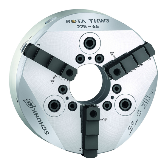
For lubrication, we recommend our tried and tested special grease, LINOMAX plus. Unsuitable lubricants can have a negative impact on the functioning of the clamping device (clamping 07.00 | ROTA THW3 | Power Chuck | en | 1440828... - Page 12 ① Measuring head ③ Chuck jaw ② Clamping insert ④ Bridge element (IFT MA4) 07.00 | ROTA THW3 | Power Chuck | en | 1440828...
-
Page 13: Disposal
To avoid accidents and/or material damage, human access to the movement range of the machine must be restricted. 07.00 | ROTA THW3 | Power Chuck | en | 1440828... -
Page 14: Notes On Particular Risks
Never exceed the technical data specified by the manufacturer for using the clamping device. 07.00 | ROTA THW3 | Power Chuck | en | 1440828... - Page 15 There is a risk of limbs being crushed by moving parts during manual loading and unloading and the clamping procedure. Do not reach between the chuck jaws. Use loading devices. 07.00 | ROTA THW3 | Power Chuck | en | 1440828...
- Page 16 The outer diameter of the screwed-on top jaws must not exceed the outer diameter of the clamping device by more than 10%. 07.00 | ROTA THW3 | Power Chuck | en | 1440828...
-
Page 17: Technical Data
Function monitoring (piston movement and actuating pressure) must be performed in accordance with the guidelines of the Berufsgenossenschaft (employers' mutual insurance association). 07.00 | ROTA THW3 | Power Chuck | en | 1440828... -
Page 18: Clamping Force-Rpm Diagrams
Clamping force/RPM diagram for ROTA THW3 200-52 Speed of rotation [RPM] Colour Jaw ID Weight [kg] SHF 160 SFA 160 GST 140 UVB 160 Minimum required clamping force 33% 07.00 | ROTA THW3 | Power Chuck | en | 1440828... - Page 19 Clamping force/RPM diagram for ROTA THW3 265-81 Speed of rotation [RPM] Colour Jaw ID Weight [kg] SHF 250 SFA 250 GST 251 UVB 250 Minimum required clamping force 33% 07.00 | ROTA THW3 | Power Chuck | en | 1440828...
- Page 20 Clamping force/RPM diagram for ROTA THW3 400-128 Speed of rotation [RPM] Colour Jaw ID Weight [kg] SHF 315 SFA 315 GST 400 UVB 400 10,0 Minimum required clamping force 33% 07.00 | ROTA THW3 | Power Chuck | en | 1440828...
- Page 21 Clamping force/RPM diagram for ROTA THW3 630-165 Speed of rotation [RPM] Colour Jaw ID Weight [kg] SHF 400 SFA 400 13,5 GST 500-630 11,7 UVB 630 31,0 Minimum required clamping force 33% 07.00 | ROTA THW3 | Power Chuck | en | 1440828...
-
Page 22: Calculations For Clamping Force And Speed
Minimum required clamping force Speed of rotation Reduction in effective clamping force by the magnitude of the total centrifugal force, for gripping from the outside inwards. 07.00 | ROTA THW3 | Power Chuck | en | 1440828... - Page 23 The centrifugal torque of the base jaws M can be found in the table "Lathe chuck data"} 3.1 [/ 17]. The centrifugal torque of the top jaws M is calculated as per: 07.00 | ROTA THW3 | Power Chuck | en | 1440828...
-
Page 24: Calculation Example: Required Initial Clamping Force For A Given Speed
Centrifugal torque for one jaw: The chuck has 3 jaws, the total centrifugal torque is: The total centrifugal force can now be calculated: Initial clamping force during shutdown that was sought: 07.00 | ROTA THW3 | Power Chuck | en | 1440828... -
Page 25: Calculation Of The Permissible Speed In Case Of A Given Initial Clamping Force
In order to prevent damage resulting from these residual risks, the entire rotor must be dynamically balanced in accordance with DIN ISO 21940-11. 07.00 | ROTA THW3 | Power Chuck | en | 1440828... -
Page 26: Assembly
ð Chuck assembly (with cylindrical recess) } 4.5.1 [/ 28] if required: ð Assembly preparation for the chuck with reduction or expansion adapter plate } 4.5.2 [/ 31] Performing a functional check } 5.4 [/ 34] 07.00 | ROTA THW3 | Power Chuck | en | 1440828... -
Page 27: Connection Thread Draw Tube
Make sure that the surface area of the flat surface is deburred at the bore holes and is clean. 07.00 | ROTA THW3 | Power Chuck | en | 1440828... -
Page 28: Assembly Process
Chuck assembly Move the draw tube to its foremost position by actuating the clamping cylinder Piston in foremost position R1 = Push the chuck piston to its foremost position and 07.00 | ROTA THW3 | Power Chuck | en | 1440828... - Page 29 [/ 28]) and, if necessary, align at the outer diameter with gentle taps using a hammer. Tighten the mounting screws (item 31) with a torque wrench. Observe the maximum admissible torques [/ 26]. } 4.1 07.00 | ROTA THW3 | Power Chuck | en | 1440828...
- Page 30 1, 2 or 3. Check that the base jaws can move easily and check the jaw stroke. At regular intervals, check that the retainer ring (item 15) is seated firmly. 07.00 | ROTA THW3 | Power Chuck | en | 1440828...
-
Page 31: Assembly Preparation For Chuck With Reduction Or Extension Flange
After assembly, ensure that the flange is in contact with the entire surface. Check the concentricity and axial run-out of the flange (see Fig. } 4.5 [/ 28]). Then the chuck is assembled } 4.5.1 [/ 28]. 07.00 | ROTA THW3 | Power Chuck | en | 1440828... -
Page 32: Function
Function 5 Function 5.1 Function and handling The lathe chucks of type ROTA THW3 are actuated using rotating closed-center or open-center hydraulic cylinders or via a static hydraulic cylinder. The axial tensile and pressure forces are converted to the radial jaw clamping force by the wedge angle in the pistons and thrust jaw. -
Page 33: Base Jaw Position
(B). Item Designation Chuck body Monitoring pin Base jaw Depress monitoring pin Move base jaw CAUTION Excessive force (e.g. from hammer blows) will damage the clamping device. 07.00 | ROTA THW3 | Power Chuck | en | 1440828... -
Page 34: Replacement Or Renewal Of Jaws
A reliable speed limiter must be installed in the machine tool or technical equipment and proof must be provided that the speed limiter is effective! 07.00 | ROTA THW3 | Power Chuck | en | 1440828... -
Page 35: Maintenance
5. Couple the mouth of the grease gun with the lubrication nipple. 6. Fill the chuck with grease until grease is visible at the air bleed screw. 07.00 | ROTA THW3 | Power Chuck | en | 1440828... -
Page 36: Technical Condition
To do this, insert the jaw change key (item 20) into the eccentric bolt (item 4), and turn anti-clockwise to "change" position and remove base jaws from the chuck. 07.00 | ROTA THW3 | Power Chuck | en | 1440828... -
Page 37: Maintenance Intervals
Lubricating the greasing areas: Interval Demands every 30 days or normal / use of coolant after 50,000 clamping cycles every 15 days or after high / use of coolant 25,000 clamping cycles 07.00 | ROTA THW3 | Power Chuck | en | 1440828... -
Page 38: Disassembling And Assembling The Chuck
Insert the retrieval elements in the guide in the mount. Eccentric bolt (item 4) in the "lock" position. Remove screws (item 30) incl. the screw seal (item 40) of the chuck body. 07.00 | ROTA THW3 | Power Chuck | en | 1440828... - Page 39 Remove the base jaws (item 22) from the guideway. Remove the wiper (item 10) incl. the inserted O-ring (item 41) radially from the guide groove. Remove the O-ring (item 48) from the chuck body. 07.00 | ROTA THW3 | Power Chuck | en | 1440828...
- Page 40 (item 8) incl. O-ring (item 42) out of the thrust jaw. Remove the locking pin (item 9), compression spring (item 63), washer (item 62) and safety ring (item 61) from the bore hole. 07.00 | ROTA THW3 | Power Chuck | en | 1440828...
- Page 41 The chuck is assembled in the same way, but in reverse order. CAUTION When assembling the base jaws, make sure that the numbers on the base jaws match the numbers on the jaw guides. 07.00 | ROTA THW3 | Power Chuck | en | 1440828...
-
Page 42: Storage
Only store the product in dry rooms. Protect the product from major temperature fluctuations. NOTE: Before recommissioning, clean the product and all attachments, check for damage, functionality and leaks. 07.00 | ROTA THW3 | Power Chuck | en | 1440828... -
Page 43: Part List
Screws Lock Screw seal O-ring O-ring O-ring O-ring O-ring O-ring 225 / 265 / 315 / 400 O-ring O-ring O-ring 265 / 315 / 400 / 500 / 630 07.00 | ROTA THW3 | Power Chuck | en | 1440828... - Page 44 Pressure piece Safety ring Washer Compression spring Compression spring Cylindrical pin Cylindrical pin Cylindrical pin Ball Cylindrical pin Compression spring Cylindrical pin Air bleed screw Lubrication nipples Emblem Compression spring 07.00 | ROTA THW3 | Power Chuck | en | 1440828...
-
Page 45: Drawing
Drawing 9 Drawing Full chuck 07.00 | ROTA THW3 | Power Chuck | en | 1440828... - Page 46 Drawing Thrust jaw 07.00 | ROTA THW3 | Power Chuck | en | 1440828...
- Page 47 Drawing Mount 07.00 | ROTA THW3 | Power Chuck | en | 1440828...
- Page 48 Drawing Retaining ring center sleeve from size 265 07.00 | ROTA THW3 | Power Chuck | en | 1440828...
- Page 49 07.00 | ROTA THW3 | Power Chuck | en | 1440828...
- Page 50 07.00 | ROTA THW3 | Power Chuck | en | 1440828...
- Page 51 2B, NCA, NCD, NCE, NC, NCF, NCK, NCO, NCR, NCS, NCX, TH, THW, HSH, HSA, DFF Heinz-Dieter SCHUNK GmbH & Co. Spanntechnik KG certifies that the above-mentioned products, when used as intended and in compliance with the operating manual and the warnings on the product, are safe according to the national regulations and: −...
- Page 52 H.-D. SCHUNK GmbH & Co. Spanntechnik KG Lothringer Str. 23 D-88512 Mengen Tel. +49-7572-7614-0 info@de.schunk.com schunk.com Folgen Sie uns I Follow us Wir drucken nachhaltig I We print sustainable...
Need help?
Do you have a question about the ROTA THW3 and is the answer not in the manual?
Questions and answers