
Related Manuals for Gazebo penguin FLORENCE 41215-GP-12


Summary of Contents for Gazebo penguin FLORENCE 41215-GP-12
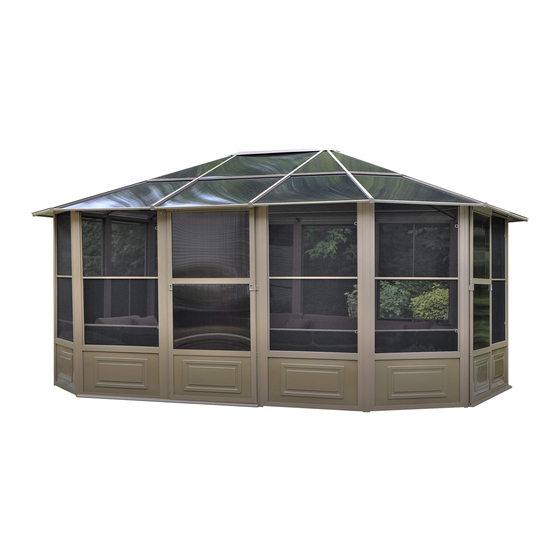
- Page 1 MANUEL D'INSTRUCTIONS INSTRUCTION MANUAL FLORENCE-12x15TOIT EN POLYCARBONATE FLORENCE - 12 x 15 POLYCARBONATE ROOF sku:41215-GP-12 sku:41215-GP-32...
- Page 2 NE DÉTRUISEZ PAS LES BOÎTES AVANT QUE L'ABRI SOIT COMPLÈTEMENT ASSEMBLÉ POUR LA RÉFÉRENCE FUTURE, PRENEZ DES PHOTOS DE TOUS LES SIX COTÉS DE CHACUNES DES BOITES À LA RÉCEPTION DU PRODUIT. VEUILLEZ VÉRIFIER LE CONTENU DE CHAQUE BOÎTE A L’AIDE DE LA LISTE DES PIÈCES 12pi x 15pi / 3.66m x 4.57m Solarium LES INSTRUCTIONS D'INSTALLATION IMPORTANTE: RETENIR POUR LA FUTURE RÉFÉRENCE, LIRE ATTENTIVEMENT...
- Page 3 12X15 Solarium DESCRIPTION DESSIN DESSIN DESCRIPTION 23-087 23-086 Cadre Adjacent Cadre à la porte Régulier (avec trous supplémentaires) 08-132 23-309 Cadre de la Porte porte Coulissante Coulissante 08-133 08-136 Rail de porte Pièce de Supérieur Connexion (206cm) (200.6cm) 08-137 08-138 Rail de porte Butoir en Inférieur (206cm)
- Page 4 DESCRIPTION DESSIN DESSIN DESCRIPTION 08-148 08-147 Embout pour Jonction Chevron de toit Centrale 08-149 08-150 Bordure de Renfort Finition (120.6cm) (94.5cm) 08-151 08-152 Bordure de Renfort Finition (94.4cm) (120.6cm) 08-153 08-154 Bordure de Renfort Finition (94.4cm) (120.6cm) 08-155 (24 ¼”X42 ¼”) 08-156 Panneau M5*20...
- Page 5 DESCRIPTION DESSIN DESSIN DESCRIPTION 08-187 08-168 Rondelle Boulon 08-189 08-193 Bouchon en Écrou Borgne Plastique 08-195 08-196 (47”x47 ½”) (46 ¼”x43”) Bottom Roof Panneau Inf Left Panel rieur en coin 08-197 08-198 (24 ¼”x42 ½”) (46 ¼”x43”) Panneau Inf Panneau rieur Droit Supérieur Droit 08-134...
- Page 6 DESCRIPTION DESSIN DESSIN DESCRIPTION 23-216 Tournevis Clé Hexagonale 23-223 Clé Hexagonale...
- Page 7 PIÈCES DE REMPLACEMENT DISPONIBLES DESCRIPTION DESSIN DESCRIPTION DESSIN 23-090 08-219 Panneau Inf rieur en Acier Fenêtre PVC (pour panneau (avec cadre) muraux) 10-493 23-091 Fenêtre PVC Panneau Inférieur (matériel en Acier (pour les seulement) portes) 15-097 85-417-P Rouleau de Rouleau de Porte Éclisse pour Porte Assemblé...
- Page 8 Note: The dimensions are approximate.
- Page 9 Avant d'assembler le Solarium Ne détruisez pas les boîtes tant que l'unité n'est pas complètement assemblée. Outils nécessaires : Escabeau 6'- 8’ Tournevis Phillips #2, Tournevis Robertson #2 Maillet en caoutchouc Limes Pièce en bois de 12 pouces En fonction de l'emplacement, décidez de l'endroit où vous souhaitez placer le solarium. Veuillez noter que la porte coulissante "C"...
- Page 10 ÉTAPE 1 "vue du dessus" 1-A. Les moustiquaires doivent être placés à l’extérieur de l’unité. 1-B. Le cadre de la porte coulissante (D) est abaissé, assurez-vous qu’il se trouve à l’intérieur.
- Page 11 ÉTAPE 2 "vue du dessus" 2. Relier le cadre régulier (A) au cadre de la porte coulissante (D) à l’aide du connecteur extérieur (I) et du connecteur intérieur (J). ATTENTION : : Connectez d’abord le connecteur (I) comme indiqué sur l’image.
- Page 12 ÉTAPE 3 "vue du dessus" "vue du dessus" 3. Connectez les cadres réguliers et les cadres de portes coulissantes dans l’ordre, conformément à l’ordre de l’image. ATTENTION : : Le cadre adjacent (B) et le cadre de la porte coulissante peuvent être installés dans n’importe quelle position, à...
- Page 13 ÉTAPE 4 ±5mm 4. Assurez-vous que les mesures en diagonale sur l’ensemble des cadres sont à moins de 5mm de la même distance après avoir effectué cette étape. ÉTAPE 5 5. Placez le rail inférieur de la porte (G) à l’intérieur du cadre de la porte coulissante (D) et du cadre adjacent à...
- Page 14 ÉTAPE 6 6.1. Insérez le rail de la port supérieur (F) dans la pièce de connexion située en haut de la porte coulissante (C). 6.2. Fixez le bouchon en plastique (H) aux deux extrémités du rail de porte supérieur (F) à l’aide des boulons (Bb).
- Page 15 ÉTAPE 7 ① ② Cc-2 ③ ④ Retirez le petit carré ici et vous pourrez l'utiliser Dd-L Dd-R Vue intérieure Vue intérieure 7.1. Placez la porte coulissante assemblée (C) à la verticale, insérez l’extrémité inférieure dans le rail de la porte inférieure (G) et fixez l’extrémité supérieure avec les boulons (Cc-2/Ww). 7.2.
- Page 16 ÉTAPE 8 8.1. Fixez les chevrons de toit (L) au capuchon central (N) à l’aide des boulons (Bb). 8.2. Utilisez les vis (Z) pour fixer les chevrons (L) dans le haut des panneaux en passant par la pièce métallique attachée aux chevrons (L). ATTENTION : Les chevrons doivent être fixés à...
- Page 17 ÉTAPE 9 9.1. Fixez les chevrons (L) au capuchon central (N) à l’aide des boulons (Bb). 9.2. Utilisez les vis (Z) pour fixez les chevrons (L) sur la partie supérieure des panneaux en passant par la pièce métallique fixée au chevron (L). ATTENTION : : Les chevrons doivent être fixés à...
- Page 18 ÉTAPE 10 10. Utilisez la même méthode pour assembler les chevrons (K) des panneaux inclinés. Les chevrons (K) doivent être fixés au support de montage en utilisant le trou le plus éloigné de l’angle de l’unité. ATTENTION : : Ne serrez pas les boulons tout de suite car vous devrez peut-être ajuster l’angle lors de l’insertion des panneaux de toit en polycarbonate.
- Page 19 ÉTAPE 11 Aa/Y/LI/Qq Aa/Y/LI Remarque : Veillez à ce que le côté avec la protection UV soit orienté vers le haut. 11.1. Utilisez l’écrou (Hh) et les rondelles (Gg) pour fixer le capuchon du haut (M) au capuchon central (N). 11.2.
- Page 20 ÉTAPE 12 O/P/Q/Pp Après Avant O/P/Q/Pp De ce côté-là! O/P/Q/Pp 12. Après avoir inséré les panneaux de toit en polycarbonate, insérez les joints de toit intermédiaires en aluminium (O/P/Q/Pp) dans les chevrons de toit. NOTE : Les trous d’évacuation des joints de toit intermédiaires en aluminium (O/P/Q/Pp) doivent être situés en bas.
- Page 21 ÉTAPE 13 Kk/Mm/Jj/Rr Kk/Mm/Jj/Rr Remarque : Veillez à ce que le côté avec la protection UV soit orienté vers le haut. Avant Après O/P/Q/Pp Kk/Mm/Jj/Rr "vue du dessus" 13. Insérez les panneaux de toit extérieurs (Jj/Kk/Mm/Rr) en vous référant à l’image ci-dessus. Les panneaux doivent se chevaucher d’environ deux pouces sous les panneaux de toit supérieurs et dans les joints de toit en aluminium.
- Page 22 ÉTAPE 14 14. REMARQUE : Pour ajuster les joints intermédiaires : Une fois que tous les panneaux de toit en polycarbonate sont en place, utilisez un petit morceau de bois et un marteau, puis taper sur le milieu du joint pour l’abaisser. (Essayez de tenir le joint central et les panneaux de toit en même temps pour vous assurer qu’ils soient alignés.
- Page 23 ÉTAPE 15 "Vue de dessous" "Vue de dessous" Vue de dessous "Vue de dessous" "Vue de dessous" 15. Une fois l’installation des bordures de finition terminée, Commencez à fixer les renforts de toit (T/V/X/Tt) à l’aide des boulons (Ff). Fixez le renfort (Uu) sur le chevron du toit (L) à l’aide des boulons (Ff).
- Page 24 ÉTAPE 16 16. Ā l’intérieur de chacun des panneaux (A/B), enfoncer les deux bouchons en plastique (Ll) dans le sol, puis visser les panneaux à l’aide des boulons (Ee) pour chacun des panneaux. A l'intérieur du Solarium Trous de drainage Remarques spéciales : 1.
- Page 25 Suggestions Les suggestions ci-dessous ne sont que des suggestions pour permettre le drainage, qui variera en fonction du matériau, de la planéité et de la pente de votre revêtement de sol. Pour les sols en béton Depuis l'extérieur de l'unité, il est suggéré de percer l'extrémité inférieure des panneaux pour permettre le drainage lors de l'installation sur des sols en béton.
- Page 26 • Advenant que le produit soit endommagé ou que la période de garan�e soit expirée, veuillez contacter le département d’expérience client de Gazebo Penguin afin d’obtenir une liste complète des pièces de remplacement et des prix. LIMITATIONS ET EXCLUSIONS À LA GARANTIE 1.
- Page 27 MANUEL D'INSTRUCTIONS INSTRUCTION MANUAL FLORENCE-12x15TOIT EN POLYCARBONATE FLORENCE - 12 x 15 POLYCARBONATE ROOF sku:41215-GP-12 sku:41215-GP-32...
- Page 28 Some jurisdictions may require permits for, or otherwise regulate, installation and use. For assistance with assembly, installation, parts, or customer service, contact Gazebo Penguin Customer Service Department at the numbers listed below (English & French, Mon-Fri 8:00 AM to 4:00 PM EST):...
- Page 29 12X15 Solarium PACKED PACKED DESCRIPTION DRAWING DESCRIPTION DRAWING IN BOX IN BOX 23-087 23-086 FRAME NEXT REGULAR TO DOOR B FRAME (with extra holes) 23-309 08-132 SLIDING SLIDING DOOR DOOR FRAME 08-133 08-136 CONNECTING TOP DOOR PIECE RAIL Length 206 cm Length 200.6 cm 08-137 08-138...
- Page 30 PACKED PACKED DESCRIPTION DRAWING DESCRIPTION DRAWING IN BOX IN BOX 08-147 08-148 MIDDLE ROOF ROOF JOINT RA FTER CAP 08-150 08-149 ROOF CROSS EDGING Length 120.6 cm Length 94.4 cm 08-152 08-151 ROOF CROSS EDGING Length 120.6 cm Length 94.4 cm 08-154 08-153 ROOF CROSS...
- Page 31 PACKED PACKED DESCRIPTION DRAWING DESCRIPTION DRAWING IN BOX IN BOX 08-168 08-187 BOLT WASHER 08-193 08-189 PLASTIC ACORN NUT PLUG 08-195 08-196 (47”x47 ½”) (46 ¼”x43”) BOTTOM BOTTOM ROOF ROOF LEFT CORNER PANEL PANEL 08-198 08-197 (46 ¼”x43”) (24 ¼”x42 ½”) BOTTOM TOP RIGHT ROOF RIGHT...
- Page 32 PACKED PACKED DESCRIPTION DRAWING DESCRIPTION DRAWING IN BOX IN BOX 23-216 Screw driver Allen wrench 23-223 Allen wrench...
- Page 33 AVAILABLE REPLACEMENT PARTS DESCRIPTION DRAWING DESCRIPTION DRAWING 23-090 08-219 BOTTOM PVC WINDOW STEEL PANEL (in frame) (for wall panels) 10-493 23-091 PVC WINDOW BOTTOM (replacement STEEL PANEL material only) 85-417-P 15-097 ROUND SPLINE DOOR WHEEL FOR PVC ASSEMBLY WINDOW 11-736 15-123 RECEIVER PIN FOR PVC...
- Page 34 Note: The dimensions are approximate.
- Page 35 Before you assemble the Solarium PLEASE DON'T DESTROY THE BOXES UNTIL COMPLETELY ASSEMBLED Tools needed: Step Ladder 6’-8’ #2 Phillips, #2 Robertson Screwdriver (not supplied) Rubber Mallet Various Files 12” piece of wood Based on the location, decide where you would like to position the solarium. Remember the sliding door with “C”...
- Page 36 Step 1 "Top View" 1. Put the Frame next to door(B) and the Sliding Door Frame (D) upright and connect them by using the two Connecting Pieces (E) as shown in the picture 1-A:The screens to be on the outside of the unit. 1-B:The Stiding Door Frame (D) has a step down, Make sure that itis on the inside...
- Page 37 Step 2 "Top View" 2. Connect the Regular Frame(A)with the Sliding Door Frame (D) by using the Outside Connectors (I) and Indide Connector (J). Note: first connect the connector (I) as shown in the figure.
- Page 38 Step 3 "Top View" "Top View" 3. Connect the Regular frames and the Sliding Door Frames in sequence according to the order in the picture. Note: Frame Next To Door (B) and Sliding Door Frame (D) can be installed at any position, as long as Frame Next To Door (B) and Sliding Door Frame (D) are next to each other...
- Page 39 Step 4 ±5mm 4. Note: Be sure measurements diagonally across the overall frame are within 5mm of the same distance after completing this step. Step 5 5. Put the Bottom Door Rail (G) on the inside of the Sliding Door Frame (D) and the Frame next to Door (B), then fix them by using the Bolts(CC).
- Page 40 Step 6 6.1 Insert the Top Door Rail (F) into the connect piece on the top of the Sliding Door(C) 6.2 Fix the Plastic Stopper(H)onto the both ends of the Top Door Rail (F) by using the Bolts (Bb). 6.3 Fix the Upper Door Rail End Cap (Nn) onto the both ends of the Top Door Rail (F) by using the Bolts (Oo).
- Page 41 Step 7 ① ② Cc-2 ③ ④ Remove the small square here and you can use it. Dd-L Dd-R “INSIDE VIEW ” “INSIDE VIEW ” 7.1 Put the assembled Sliding Door (C) upright, insert the lower end into the Bottom Door Rail (G), and fix the upper end with Bolts (Cc 2-Ww).
- Page 42 Step 8 8.1 Attach roof rafters (L) to the central hub (N) using bolt (Bb). 8.2 Use screw (Z) to affix the rafters (L) onto the top of panels going through the metal piece attached to the rafter (L). Note: Rafters must be affixed where panels connect to each other.
- Page 43 Step 9 9.1 Attach roof rafters (L) to the central hub (N) using bolt (Bb). 9.2 Use screw (Z) to affix the rafters (L) onto the top of panels going through the metal piece attached to the rafter (L). Note: Rafters must be affixed where panels connect to each other.
- Page 44 Step 10 10. Use the same method to assemble roof rafters (K) for the angled panels. The rafters (K) should be affixed to the mounting bracket using the hole that will be furthest away from the corner of the unit. Note : Do not tighten the bolts right away as you may have to adjust the angle when inserting the PC roof panels.
- Page 45 Step 11 Aa/Y/LI/Qq Aa/Y/LI Note:"Make sure the one with the UV protection to be facing up." 11.1 Use nut (Hh) and washer (Gg) to affix the top cap (M) to the central hub (N). 11.2 First remove the protective layer from the PC roof panels, then insert them (Y, Aa, Ll, Qq) into the roof rafters according to the below drawing instructions.
- Page 46 Step 12 O/P/Q/Pp A er Before O/P/Q/Pp This side up ! O/P/Q/Pp 12. After inserting the polycarbonate roof panels, insert the aluminium middle roof joints Middle Roof Joint (O), Middle Roof Joint (P), Middle Roof Joint (Q)and Middle Roof Joint (Pp) into the roof rafters. NOTE: The drain holes on the aluminium joints (O/P/Q) should be at the bottom.
- Page 47 Step 13 Kk/Mm/Jj/Rr Kk/Mm/Jj/Rr Note:"Make sure the one with the UV protection to be facing up." Before A er O/P/Q/Pp Kk/Mm/Jj/Rr TOP VIEW 13. After the installation on the middle roof joints complete, insert the bottom PC roof panels (Jj, Kk, Mm, Rr) according to below drawing. They should overlap about two inches under the upper PC roof panels and into the aluminum middle roof joints.
- Page 48 Step 14 14. Once the roof is complete, use the aluminium edging (S/U/W/Ss) to surround the edges of the polycarbonate roof using bolts (Bb) to fasten the rafter cap (R) and the edging, tighten securely. NOTE: At this step, you may need to tap the polycarbonate with a mallet and a piece of wood to get the edging properly setup.
- Page 49 Step 15 Bottom View 15. Once the installation of the edging complete, start affixing the roof cross bars (T, V, X, Tt) using bolt (Ff). Affix the top cross bars (Uu) onto the roof rafter (L) using bolt (Ff).
- Page 50 Step 16 Inside each of the panels (A, B), push two plastic plugs (Ii) into the ground, and then screw down the panels using two screws (Ee) for each panel. Special notes: 1. To remove windows (08-219), pull 1 pin out of the lock position and push the frame to the end of the track, then ease the window out of the tracks one side at a time.
- Page 51 Suggestions The suggestions below are only suggestions in order to permit drainage, these will vary depending on your flooring – material, flatness and slope. From the outside of the unit, it is suggested to drill at the bottom end of the panels to permit drainage when installing on concrete floors.
- Page 52 7. The product is warranted only if installed in accordance with Gazebo Penguin's written instructions included with the product.
Need help?
Do you have a question about the FLORENCE 41215-GP-12 and is the answer not in the manual?
Questions and answers