Advertisement
Applications
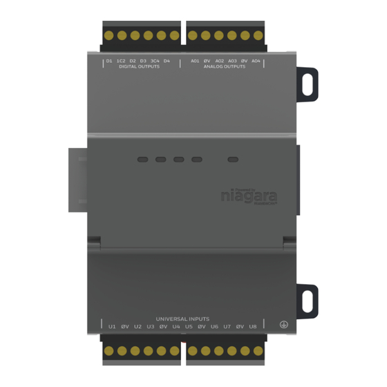
This document describes how to mount and wire an FX-SC8XIOR16-0 (IOR-16) option module for
an FX80 controller. The IOR-16 is designed for the remote monitoring and control of applications
to facilitate end-to-end automation and device-to-enterprise integration. It expands an FX80
Supervisory Controller with 16 I/O points consisting of the following:
• Eight universal inputs (UI): Type 3 (10K) thermistors, 0-100kΩ, 0-10 VDC, 0-20 mA with external
resistor
• Four relay outputs (RO): Form A contacts, 24 VAC @ 0.5 A rated
• Four analog outputs (AO) (1-10 VDC)
The IO module uses DIN rail mounting and has two end-mounted five-pin connectors that support
direct-chaining to other IOR-16 modules or FX-SC8XIOR34-0 (IOR-34) modules. Communications
to an FX80 Controller use RS-485 multidrop on three wires of an end-mounted five-pin connector.
The other two wires on that connector are for INPUT power (15 VDC) and are supplied from a DIN-
mountable option (IOR-34) or a third party 13.5 VDC to 15.75 VDC power supply. The RS-485 bus is
wired back to COM1 or COM2 of the FX80 controller.
Part No. 24-10143-01701 Rev. A
2019-03-22
FX-SC8XIOR16-0 Module Installation
Figure 1: FX-SC8XIOR16-0 Module
Instructions
*241014301701A
(barcode for factory use only)
Advertisement
Table of Contents

Related Manuals for Johnson Controls FX-SC8XIOR16-0


Summary of Contents for Johnson Controls FX-SC8XIOR16-0
- Page 1 Instructions Applications This document describes how to mount and wire an FX-SC8XIOR16-0 (IOR-16) option module for an FX80 controller. The IOR-16 is designed for the remote monitoring and control of applications to facilitate end-to-end automation and device-to-enterprise integration. It expands an FX80 Supervisory Controller with 16 I/O points consisting of the following: •...
-
Page 2: North American Emissions Compliance
Installation Unpack the FX-SC8XIOR 16-0 and inspect the contents of the package for damaged or missing components. If the module is damaged, contact the Johnson Controls® Product Sales Operations team and return any damaged components for repair or replacement. Power supply options An FX80 controller can support up to a maximum of sixteen IOR-16 modules through a single RS-485 bus. - Page 3 Table 3: Voltage drop per 100 feet run (30m) of paired wire Gauge Load Current (AWG) 0.10A 0.25A 0.5A 1.0A 1.5A 2.0A 4.0A 0.020 0.05 0.10 0.20 0.30 0.40 0.80 0.032 0.08 0.16 0.32 0.48 0.64 1.27 FX-SC8XIOR16-0 Module Installation Instructions...
-
Page 4: Parts Included
Precautions Warning Risk of Electric Shock Disconnect the power supply before making electrical connections. Contact with components carrying hazardous voltage can cause electric shock and may result in severe personal injury or death FX-SC8XIOR16-0 Module Installation Instructions... - Page 5 Risk of Property Damage Connect S terminal wiring as shown in Figure 7 or communication errors may result. S terminal serves as reference ground between isolated RS-485 ports on FX80 Supervisory Controllers and IOR-16 and IOR-34 modules. FX-SC8XIOR16-0 Module Installation Instructions...
-
Page 6: Mounting On A Din Rail
Mounting on a DIN rail ensures accurate alignment of connectors between all modules. • If DIN rail mounting is impractical, you can use screws in mounting tabs on the IOR-16. Pull the module’s locking clip down. FX-SC8XIOR16-0 Module Installation Instructions... - Page 7 DIN rail end clips. IOR-16 board layout and terminals The IOR-16 module provides eight universal inputs, four digital relay outputs, and four 0-10 VDC analog outputs. The following table shows the wiring terminal positions and LED locations. FX-SC8XIOR16-0 Module Installation Instructions...
- Page 8 Description Digital Relay Outputs (D1 to D4) Analog VDC Outputs Relay Output LEDs RS-485 Staus LED Five-pin connector 15 VDC Power RS-485 Earth Grounding Connector Lug Universal Inputs (U1 to U4) Universal Inputs (U5 to U8) FX-SC8XIOR16-0 Module Installation Instructions...
- Page 9 Keep these wires as short as possible. See Figure 4 for the location of the earth grounding wire. Figure 4: Earth ground connections required to each IOR-16 Note: Connect any remote IO-R-16 modules to a nearby earth ground in the same manner. FX-SC8XIOR16-0 Module Installation Instructions...
- Page 10 See Voltage drop considerations. • For other wiring on the five-position end connector, see RS-485 Communications. • Do not apply power until all other wiring is completed. See Power up and initial checkout. FX-SC8XIOR16-0 Module Installation Instructions...
- Page 11 • END - RS485 biasing and a termination: 562Ω bias resistors and 150Ω termination resistor • MID - RS485 biasing or termination: 47.5K bias resistors with no termination resistor The following list contains best practice for the switch settings: FX-SC8XIOR16-0 Module Installation Instructions...
- Page 12 Important: Connect S terminal wiring as shown in Figure 7 or communication errors may result. S terminal serves as reference ground between isolated RS-485 ports on FX80 controller and IOR-16 and IOR-34 modules. Figure 7: RS-485 wiring from the FX80 to one or more IOR-16 Modules using daisy-chain connection FX-SC8XIOR16-0 Module Installation Instructions...
- Page 13 Inputs support self-powered 0–10 VDC sensors. Input impedance is greater than 5kΩ. 0–10 V accuracy is ±2% of span, without user calibration. Then following image shows the wiring diagram for a 0–10 VDC sensor. 0–10 VDC sensors require a Voltage Input Point. FX-SC8XIOR16-0 Module Installation Instructions...
- Page 14 25 ms.) • Standard dry contacts must have a 1 Hz (or less) COS frequency, with minimum dwell time >500 ms. (Contacts must remain open at least 500 ms and be closed at least 500 ms.) FX-SC8XIOR16-0 Module Installation Instructions...
- Page 15 Important: Relays are not rated for AC mains (line level) powered loads (instead, 24 V maximum). Use an external 24 V transformer or a 24 VDC power supply to power loads. Use a RelayOutputWritable in the station for each output. FX-SC8XIOR16-0 Module Installation Instructions...
- Page 16 For example, for a device with a 1,000Ω input impedance, the AO would work as a 0 VDC to 4 VDC analog output. For each AO, use a Voltage Output Writable in the station database. The following image shows typical wiring for an AO: Figure 13: Analog output wiring diagram FX-SC8XIOR16-0 Module Installation Instructions...
-
Page 17: Power Up And Initial Checkout
Upgrade Firmware, do not interrupt power to the IOR-16 module and FX Supervisory Controller, or to the communications between them, until the firmware upgrade job finishes. Typically, this takes less than 2 minutes, with job completion signaled in the FX Workbench view. FX-SC8XIOR16-0 Module Installation Instructions... - Page 18 © 2019 Johnson Controls. All rights reserved. All specifications and other information shown were current as of document revision and are subject to change without notice. www.johnsoncontrols.com...
Need help?
Do you have a question about the FX-SC8XIOR16-0 and is the answer not in the manual?
Questions and answers