Advertisement
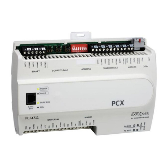
FX-PCX47 Expansion Input/Output Module
Installation Instructions
FX-PCX4711-x
Applications
The FX-PCX47 Expansion Input/Output (I/O) Module is
part of the Facility Explorer FX-PC Programmable
Controller family. The FX-PCX47 module expands the
number of inputs and outputs connected to FX-PCs to
monitor and control a wide variety of Heating,
Ventilating, and Air Conditioning (HVAC) applications.
The FX-PCX47 module operates on an RS-485
BACnet® Master-Slave/Token-Passing (MS/TP) Bus
and integrates into the Web-based Facility Explorer
system.
North American Emissions Compliance
United States
This equipment has been tested and found to
comply with the limits for a Class A digital device
pursuant to Part 15 of the FCC Rules. These limits
are designed to provide reasonable protection
against harmful interference when this equipment is
operated in a commercial environment. This
equipment generates, uses, and can radiate radio
frequency energy and, if not installed and used in
accordance with the instruction manual, may cause
harmful interference to radio communications.
Operation of this equipment in a residential area is
likely to cause harmful interference, in which case
the user will be required to correct the interference
at his/her own expense.
Canada
This Class (A) digital apparatus meets all the
requirements of the Canadian Interference-Causing
Equipment Regulations.
Cet appareil numérique de la Classe (A) respecte
toutes les exigences du Règlement sur le matériel
brouilleur du Canada.
Installation
Observe these guidelines when installing an
FX-PCX47:
•
Transport the FX-PCX47 module in the original
container to minimize vibration and shock damage.
Refer to the
QuickLIT Web site
•
Verify that all parts shipped with the FX-PCX47
module are present.
•
Do not drop the FX-PCX47 module or subject it to
physical shock.
Parts Included
•
one FX-PCX47 module with removable terminal
blocks
•
one installation instructions sheet
Materials and Special Tools Needed
•
three fasteners appropriate for the mounting
surface (M4 screws or #8 screws)
•
one 20 cm (8 in.) or longer piece of 35 mm DIN rail
and appropriate hardware for DIN rail mount (only)
•
small straight blade screwdriver for securing wires
in the terminal blocks
Mounting
Observe these guidelines when mounting an
FX-PCX47 module:
•
Ensure the mounting surface can support the
FX-PCX47, DIN rail, and any user-supplied
enclosure.
•
Mount the FX-PCX47 module on 35 mm DIN rail
whenever possible.
•
Mount the FX-PCX47 module in the proper
mounting position (Figure 1).
•
Mount the FX-PCX47 module on a hard, even
surface whenever possible in wall-mount
applications.
•
Use shims or washers to mount the FX-PCX47
module securely and evenly on the mounting
surface.
•
Mount the FX-PCX47 module in an area free of
corrosive vapors and observe the Ambient
Conditions in the Technical Specifications section.
FX-PCX47 Expansion Input/Output Module Installation Instructions
Part No. 24-10144-122, Rev. —
Issued April 12, 2011
for the most up-to-date version of this document.
1
Advertisement
Table of Contents

Related Manuals for Johnson Controls FX-PCX4711 Series


Summary of Contents for Johnson Controls FX-PCX4711 Series
- Page 1 FX-PCX47 Expansion Input/Output Module Installation Instructions Part No. 24-10144-122, Rev. — FX-PCX4711-x Issued April 12, 2011 Refer to the QuickLIT Web site for the most up-to-date version of this document. Applications • Verify that all parts shipped with the FX-PCX47 module are present.
-
Page 2: Wall Mount Applications
• Provide for sufficient space around the FX-PCX47 7-1/2 module for cable and wire connections, easy cover removal, and adequate ventilation through the FX-PCX47 module (50 mm [2 in.] minimum on the top, bottom, and front of the FX-PCX47 module). •... - Page 3 Figure 3: FX-PCX4711 Module Physical Features and Wiring Terminals FX-PCX47 Expansion Input/Output Module Installation Instructions...
- Page 4 Wiring When connecting the FX-PCX47 module to an FC Bus, wire the bus terminal block plugs on the FX-PCX47 CAUTION: Risk of Electric Shock. module, and the other controllers in a daisy-chain Disconnect power supply before making configuration using 3-wire twisted, shielded cable as electrical connections to avoid electric shown in Figure 4.
- Page 5 Supply Power lengths. Terminal Block Plug Wires from In addition to the wiring guidelines in Table 1, observe Johnson Controls these guidelines when wiring FX-PCX47 module inputs 24 VAC, Class 2 and outputs: Power Transformer • Run all low-voltage wiring and cables separate...
- Page 6 See Guideline A in Table 2. Internal 12 V, 15k ohm pull up Qualified Sensors: 0–2k potentiometer, RTD (1k Nickel [Johnson Controls® sensor], 1k Platinum, and A99B Silicon Temperature Sensor) Negative Temperature Coefficient (NTC) Sensor (10k Type L, 10k JCI Type II, 2.252k Type II) Binary Input - Dry Contact Maintained Mode See Guideline A in Table 2.
- Page 7 Table 1: I/O Terminal Blocks, Functions, Ratings, Requirements, and Cables (Part 2 of 3) Terminal Block Terminal Function, Ratings, and Requirements Determine Wire Size and Label Labels Maximum Cable Length ANALOG OUTn Analog Output - Voltage Mode (0–10 VDC) See Guideline A in Table 2. (Outputs) 10 VDC maximum output voltage 10 mA maximum output current...
- Page 8 Table 1: I/O Terminal Blocks, Functions, Ratings, Requirements, and Cables (Part 3 of 3) Terminal Block Terminal Function, Ratings, and Requirements Determine Wire Size and Label Labels Maximum Cable Length CONFIGURABLE OUTn Analog Output - Voltage Mode (0–10 VDC) See Guideline A in Table 2. (Outputs) 10 VDC maximum output voltage 10 mA maximum output current...
- Page 9 Maximum Cable Length versus Load Current Use Figure 8 to estimate the maximum cable length relative to the wire size and the load current (in mA) when wiring inputs and outputs. Length 137.2 m 450 ft 121.9 m 400 ft 106.7 m 350 ft 1.5 mm (18 AWG) 91.4 m 300 ft...
-
Page 10: Setup And Adjustments
Table 4 shows and describes the valid FC Bus and address numbers with no gaps in the device address SA Bus devices addresses for Johnson Controls® range. The controllers do not need to be connected to MS/TP communications bus applications. - Page 11 Table 4: FC Bus Device Address Descriptions Device Description Address Binary Output Source Power Reserved for FC Bus supervisory controller. Selection Jumpers 1–3 Reserved for peripheral devices. 4–127 Available for FX-PCGs on the FC bus and FX-PCXs on the SA or FC Bus. Switch Analog Input Disables (off) or Enables (on) a controller for...
-
Page 12: Troubleshooting
UI terminals, which maintains the specifications, replace the unit. For a replacement 4 to 20 mA current loop circuit even when power to the module, contact the nearest Johnson Controls FX-PCX is interrupted or off. representative. IMPORTANT: Current Loop jumpers must be in the (default) Disabled position for all UIs that are not set up to operate as 4 to 20 mA analog inputs. -
Page 13: Technical Specifications
Table 6: Status LEDs and Description of LED States LED Label Normal Descriptions of LED States Color State POWER Green On Steady Off Steady = No Supply Power or the FX-PCX polyswitch/resettable fuse is open. Check Output wiring for short circuits and cycle power to FX-PCX module. On Steady = Power Connected FAULT Off Steady... - Page 14 The performance specifications are nominal and conform to acceptable industry standard. For application at conditions beyond these specifications, consult the local Johnson Controls® office. Johnson Controls, Inc. shall not be liable for damages resulting from misapplication or misuse of its products.
Need help?
Do you have a question about the FX-PCX4711 Series and is the answer not in the manual?
Questions and answers