Table of Contents
Advertisement
Quick Links
UL Listed GS-20/25 and GS-40/45 Series
Single-block Multi-function Gas Control Valves
x GS-_ _1_ (On/Off with Flow Adjustment)
x GS-_ _2_ (On/Off Step-slow Opening with Flow Adjustment)
© 1998 Johnson Controls, Inc.
Part No. 24-8711-374, Rev. -
Code No. LIT-121905
All manuals and user guides at all-guides.com
Gas Combustion Combination Controls and Systems Section G
Installation Sheets Manual 121
Technical Bulletin GS-20/25
GS-40/45
Issue Date 1298
Page
www.johnsoncontrols.com
3
3
3
4
5
5
6
7
8
9
9
10
10
10
12
15
1
Advertisement
Table of Contents

Subscribe to Our Youtube Channel
Related Manuals for Johnson Controls GS Series


Summary of Contents for Johnson Controls GS Series
-
Page 1: Table Of Contents
GS-_ _2_ (On/Off Step-slow Opening with Flow Adjustment) x GS-_03_ (On/Off with Pressure Regulator) x GS-405_ (On/Off with Servo Precision Regulator) x GS-406_ (On/Off with Gas/Air Ratio Control) Repairs and Replacement © 1998 Johnson Controls, Inc. Part No. 24-8711-374, Rev. — www.johnsoncontrols.com Code No. LIT-121905... - Page 2 All manuals and user guides at all-guides.com 2 G—UL Listed GS-20/25 and GS-40/45 Series Single-block Multi-function Gas Control Valves Technical Bulletin...
-
Page 3: Introduction
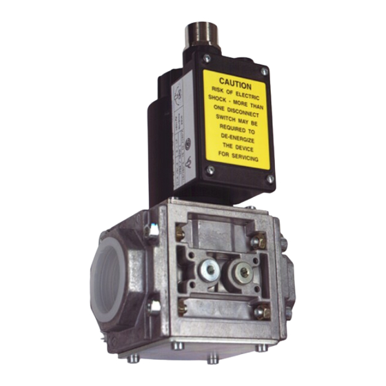
Introduction Figure 1: UL Listed GS Series Single-block Multi-function Control Valves The UL Listed GS Series single-block multi-function gas control valves Application are intended for use on atmospheric and forced-draft gas burners in heating installations. This multi-functional control on a single-block valve body provides a compact answer to gas train applications. -
Page 4: Specifications
The performance specifications are nominal and conform to acceptable industry standards. For application at conditions beyond these specifications, consult the local Johnson Controls office. Johnson Controls, Inc. shall not be liable for damage resulting from misapplication or misuse of its products. -
Page 5: Installation
IMPORTANT: This technical bulletin is intended as a guide for authorized service personnel installing or servicing Johnson Controls products. Carefully follow all instructions in this sheet and all instructions on the appliance. Limit repairs, adjustments, and servicing to the operations listed in this sheet or on the appliance. -
Page 6: Standard Wiring (From Burner Sequence Control)
All manuals and user guides at all-guides.com The GS Series valve may be mounted on a horizontal manifold with the solenoid actuator pointed up (vertical) or in any position not exceeding 90 from the vertical. The valve may also be mounted on a vertical manifold in any position around its axis (see Figure 2). -
Page 7: Gs-406_ Connection Of The Impulse Lines
All manuals and user guides at all-guides.com Electrical Box Connection 1/2 in. NPT Conduit Thread Adapter (Factory Installed) Wiring Connections N = Common L1 = Line = Earth Ground* (* Do not connect earth ground for 24 VAC models.) Figure 3: Standard Wiring Electrical Connections The internal diameter of the impulse tubes for the combustion air (P GS-406_ and the combustion chamber pressure (P... -
Page 8: Checkout Procedure
All manuals and user guides at all-guides.com Checkout WARNING: Fire or explosion hazard. Verify that the valve Procedure functions properly and there are no gas leaks. Follow this checkout procedure before leaving the installation. Failure to verify proper valve installation, equipment operation, and gas tight connections may result in fire, explosion, property damage, and injuries or death. -
Page 9: Adjustments
All manuals and user guides at all-guides.com Adjustments IMPORTANT: All adjustments must be made in conjunction with the gas appliance and in accordance with the appliance manufacturer’s instructions. Only authorized personnel should make adjustments. See each valve model version for specific adjustments. WARNING: Explosion hazard. -
Page 10: Gs-_03_ (On/Off With Pressure Regulator)
All manuals and user guides at all-guides.com This valve provides adjustable step/slow opening for smooth ignition in a GS-_ _2_ burner application. The valve is factory set to maximum start gas position (On/Off Step- and maximum flow position. Adjust the hydraulic damper at the top of the slow Opening solenoid coil to set the desired flow rate through the valve as well as the with Flow... - Page 11 All manuals and user guides at all-guides.com To set the start gas position, energize the solenoid coil to open the valve seats. Remove the pressure tap plug (see Figure 8) located below the gas outlet pipe connection and measure the start gas pressure. The P adjustment scale indicates the factory-set start gas pressure (see Figure 9);...
-
Page 12: Gs-406_ (On/Off With Gas/Air Ratio Control)
All manuals and user guides at all-guides.com Tim e (s) 3 to 12 S eco nds Figure 10: Servo Pressure Regulator Performance vs. Timing Characteristics Cycle the valve three times to check for proper performance, leaving a minimum time of 20 seconds between cycles to evacuate the pressure chamber. - Page 13 All manuals and user guides at all-guides.com The valve not only allows a gas/air ratio adjustment, but also an offset adjustment (zero set), which allows for fine adjustment at lower ratios. With these adjustments, the outlet valve pressure (P ) calculates to: = R •...
- Page 14 All manuals and user guides at all-guides.com 0.7:1 0.6:1 (in. W.C.) (in. W.C.) (in. W.C.) (in. W.C.) Figure 13: Analyses Chart Zero Set (Z) With the correct gas/air ratio (R) set, there may be some minor deviations Adjustment (caused by friction, etc.) at very low pressures. To allow for fine adjustment of the valve, the zero set can be changed.
-
Page 15: Repairs And Replacement
Repairs and Replacement Field repairs must not be made, except to replace the filter or strainer. For a replacement part, contact the nearest Johnson Controls representative or the original equipment manufacturer. CAUTION: Label all wires prior to disconnection when servicing valves. - Page 16 All manuals and user guides at all-guides.com 8. Paint the pipe connections and flanges of the valve with a rich soap and water solution. If bubbles occur, this is an indication of a leak. To stop a leak, tighten joints and pipe connections. Replace the part if the leak cannot be stopped.
Need help?
Do you have a question about the GS Series and is the answer not in the manual?
Questions and answers