Table of Contents
Advertisement
Quick Links
Instructions
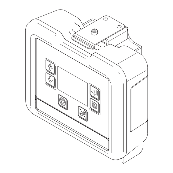
DCM and ADCM
Display Control Module (DCM) and Advanced Display Control Module (ADCM), used to
monitor and control flow rate and track material use. For professional use only.
See page 3 for kit information, including approvals.
Important Safety Instructions
Read all warnings and instructions in this
manual before using the equipment. Be
familiar with the proper control and
usage of the equipment. Save these
instructions.
332013G
EN
Advertisement
Table of Contents

Related Manuals for Graco 24L096


Summary of Contents for Graco 24L096
- Page 1 Instructions 332013G DCM and ADCM Display Control Module (DCM) and Advanced Display Control Module (ADCM), used to monitor and control flow rate and track material use. For professional use only. See page 3 for kit information, including approvals. Important Safety Instructions Read all warnings and instructions in this manual before using the equipment.
-
Page 2: Table Of Contents
Graco Standard Warranty....22 Graco Information ..... . . 22... -
Page 3: Models
See Appendix A - Control Drawing 16M169, page 12 for entity parameters. * NOTE: These models are not available for sale. They are the base models used in other Graco systems. See your system manual for kit and part information. -
Page 4: Safety Symbols
Safety Symbols Safety Symbols The following safety symbols appear throughout this manual and on warning labels. Read the table below to understand what each symbol means. Symbol Meaning Symbol Meaning Ground Equipment Electric Shock Hazard Follow Pressure Relief Procedure Equipment Misuse Hazard Ventilate Work Area Fire and Explosion Hazard Eliminate Ignition Sources... -
Page 5: General Warning
General Warning General Warning The following warnings apply throughout this manual. Read, understand, and follow the warnings before using this equipment. Failure to follow these warnings can result in serious injury. WARNING FIRE AND EXPLOSION HAZARD Flammable fumes, such as solvent and paint fumes, in work area can ignite or explode. To help prevent fire and explosion: •... - Page 6 General Warning WARNING INSTRINSIC SAFETY Intrinsically safe equipment that is installed improperly or connected to non-intrinsically safe equipment will create a hazardous condition and can cause fire, explosion, or electric shock. Follow local regulations and the following safety requirements. • Installation should be in accordance with ANSI/ISA RP12.06.01 “Installation of Intrinsically Safe Systems for Hazardous (Classified) Locations”...
- Page 7 General Warning WARNING PRESSURIZED EQUIPMENT HAZARD Fluid from the equipment, leaks, or ruptured components can splash in the eyes or on skin and cause serious injury. • Follow the Pressure Relief Procedure when you stop spraying/dispensing and before cleaning, checking, or servicing equipment. •...
-
Page 8: Installation
See the identification label for the intrinsic safety rating for your model. The DCM and ADCM are designed for use with Graco Control Architecture based systems that have a compatible design. See Appendix A - Control Drawing 16M169, page 14, for installation requirements and entity parameters. -
Page 9: Grounding
Installation Grounding The DCM and ADCM are used in a variety of systems, with varying grounding requirements. Follow all instructions in your system manual. The equipment must be grounded to reduce the risk of static sparking and electric shock. Electric or static sparking can cause fumes to ignite or explode. -
Page 10: Connection Port
Installation Connection Port Display Control Module (DCM) . 2: Advanced Display Control Module (ADCM) . 3: Port Description Fiber Optic Receiver Fiber Optic Transmitter Power In/CAN Data Digital Input/Output Fiber Optic Reciever Fiber Optic Transmitter Analog Input Analog Output Analog Output Analog Input 332013G... -
Page 11: Maintenance
Maintenance Maintenance Update Software 4. Remove 4 screws, and then remove the access cover. Manual 3A1244 will accompany any necessary software updates. Follow all instructions and warnings in Manual 3A1244 to update your DCM or ADCM software. Replace Battery Replace the battery only if the clock stops functioning after disconnecting power or a power failure. -
Page 12: Diagnostic Information
Maintenance 6. Replace with new battery. Ensure battery fits under NOTE: Use only Panasonic CR2032 batteries for connector tabs before snapping other end in place. replacement. 7. Reassemble access cover and screws. 8. Snap the module back into the bracket. Diagnostic Information The LEDs on the bottom of the DCM or the ADCM give important information about system function. -
Page 13: Parts
Parts Parts Ref. Part Description Qty. MODULE 24L096 24L097 ADCM 25B475 ADCM 16P265 LABEL, warning — LABEL, identif i ca ti on Replacement Danger and Warning labels, tags, and cards are available at no cost. 332013G... -
Page 14: Appendix A - Control Drawing 16M169
Appendix A - Control Drawing 16M169 Appendix A - Control Drawing 16M169 NOTES: 1. The non-intrinsically safe terminals (power rail) must not be connected to any device which uses or generates more than Um=250 Vrms or DC unless it has been determined that the voltage has been adequately isolated. - Page 15 Appendix A - Control Drawing 16M169 DCM View . 8: ADCM View . 9: 332013G...
- Page 16 Appendix A - Control Drawing 16M169 =Fiber Optic Connection =Unspecified Apparatus with suitable Entity Parameters . 10 Calculation Procedures Divisions Zones Voc ≤ Vmax Uo ≤ Ui Isc ≤ Imax Io ≤ Ii Po ≤ Pi Po ≤ Pi Ca ≥ Ci + Ccable Co ≥...
- Page 17 Appendix A - Control Drawing 16M169 1, 2, 5, and 6: Fiber Optics Fiber Optic Receiver A (1) and B (5) Fiber Optic Transmitter A (2) and B (6) 3: CAN Data/Power In Entity Parameters CAN Data/Power Input Loads CAN Data Output Barriers Lo/Ro IEC (Zones) Vmax Imax Pi...
- Page 18 Appendix A - Control Drawing 16M169 7: Differential Analog Input Differential I/O A Output Barriers IEC (Zones) Lo/Ro La/Ra ISA (Divisions) Units μH μF μH/Ω mV_7_1: Power 5.88 50000 3250 mV_7_2: Neg 5.88 50000 325000 mV_7_3: Ground — — — —...
- Page 19 Appendix A - Control Drawing 16M169 10: Differential Analog Input B Differential I/O B Output Barriers IEC (Zones) Lo/Ro La/Ra ISA (Divisions) Units μH μF μH/Ω mV_7_1: Power 5.88 50000 3250 mV_7_2: Neg 5.88 50000 325000 mV_7_3: Ground — — —...
-
Page 20: Mounting Dimensions
Mounting Dimensions Mounting Dimensions . 11 Mounting Dimensions Width (C) Overall Depth Mounting Hole Overall Width Overall Height x Height (D) Size in. (mm) in. (mm) in. (mm) in. (mm) in. (mm) 7.2 (183) 6.0 (152) 2.8 (71) 2.5 x 3.0 0.28 (7) (64 x 76) 332013G... -
Page 21: Technical Data
Technical Data Technical Data DCM and ADCM Metric Operating Temperature 32° to 122°F 0° to 50°C Storage Temperature –22° to 140°F –30° to 60°C Non-Hazardous Location Power Supply Requirements 15 VDC, 500 mA Minimum NOTE: Use recommended power supply PN 16V680 Weight 1 lb 0.45 kg... -
Page 22: Graco Standard Warranty
With the exception of any special, extended, or limited warranty published by Graco, Graco will, for a period of twelve months from the date of sale, repair or replace any part of the equipment determined by Graco to be defective.
Need help?
Do you have a question about the 24L096 and is the answer not in the manual?
Questions and answers