
Related Manuals for LinMot FM01-37


Summary of Contents for LinMot FM01-37
- Page 1 Installation Guide Linear Modules FM01-37 NTI AG / LinMot Dok-Nr. 0185-0187-E_2V0_IG_Linear_Guides_FM01-37...
-
Page 2: Table Of Contents
Electrical Connection ..........................18 Motor cable ............................18 N-connector wiring ........................... 18 Start-up ..............................19 LinMot drive setup ........................... 19 Standard values of the coordinate system / standard installation stator ......... 19 Setting the Parameters ........................19 6.3.1 Defining Payload .......................... 19 6.3.2... - Page 3 FM01-37-xxx_xxx_1CF37Sx60-HP ....................54 11.2 FM01-37-xxx_xxx_1CF37x120F-HP ....................55 11.3 End plates ............................56 11.4 Mounting plate FM01-37-xxx_xxx_1CF37Sx60-HP ................ 57 11.5 Mounting plate FM01-37-xxx_xxx_1CF37Sx120F-HP ..............58 International Certificates ........................59 EU Declaration of Conformity CE-Marking ..................61 UK Declaration of Conformity UKCA-Marking ................62...
-
Page 4: General Information
1.4 Liability NTI AG (as manufacturer of LinMot and MagSpring products) excludes all liability for damages and expenses caused by incorrect use of the products. This also applies to false applications, which are caused by NTI AG's own data and notes, for example in the course of sales, support or application activities. -
Page 5: Safety Instructions
Before working, make sure that there are no high voltages. Fast-moving Machine Parts The sliders of LinMot linear motors are fast-moving machine parts. All necessary precautions must be taken to prevent persons approaching the moving elements during operation (provide covers, guards, etc.). - Page 6 Linear motor sliders consist of a high-precision, thin-walled stainless steel tube in which the neodymium magnets are housed. The LinMot sliders should be handled with care. Avoid contact with other sliders or iron parts as this can damage the magnets and the slider surface.
-
Page 7: Intended Use
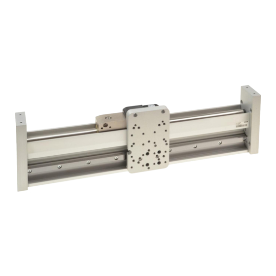
Module type 3.2 FM01 Linear Module LinMot FM01 linear modules are moving stator applications with tubular linear motors for use in industrial and commercial installations. The mechanical construction is based on a special aluminium profile to which a high- precision profile rail guide is attached. Use of ball bearings in the carriages guarantee a reliable and smooth operation, support of external forces, torques and bending moments. - Page 8 Installation Guide Linear Modules Number Item Cylinder screw End plate Parallel pin Mounting plate Connector Stator Bearing Module basis Profile rail guide Slider External sensor (set, optional) Trailing chain kit (optional) Magnetic strip Page 8 / 63 FM01-37 NTI AG / LinMot...
-
Page 9: Intended Installation
MD01 = Carriage with fixed stator (standard for stroke < 1000 mm) • MD02 = Carriage with flexible stator (standard for stroke > 1000 mm) Variant "BE01": The carriage of the linear module is equipped with 1 bearing on the profile rail. NTI AG / LinMot FM01-37 Page 9 / 63... -
Page 10: Arrangement For Multi Carriage Guidance
(see illustration). 3.6 Option external sensor Next to the LinMot linear stator’s own integrated position sensors, both incremental and absolute external encoders are available as an option for the FM01 moduls. Together with a magnetic band, the external sensors provide a high-resolution linear measurement system. -
Page 11: Technical Data Carriage Kits
Installation Guide Linear Modules 3.7 Technical data carriage kits The values for mass and friction are important for the configuration assistant of the LinMot-Talk software. FM01-..37Sx60..37Sx120... Static Load Rating (per bearing) 15400 N (3462.1 lbs) 15400 N (3462.1 lbs) -
Page 12: Installation Instructions
The following sketches show examples of different installation options. The detailed dimensions can be found in chapter 11 “Dimensions”. 4.1.1 Installation examples Example 1: Upright fixing using end plates and brackets. Example 2: Vertical fixing using T-nuts on the underside of the module basis. Page 12 / 63 FM01-37 NTI AG / LinMot... - Page 13 Example 3: Lying attachment with end plates (lengths up to 1200 mm, only with cross table trailing chains). Ordering information Item Description Item-No. Nut N8/M4 Nut for 8 mm T-slots with M4 thread 0150-2189 Nut N8/M6 Nut for 8 mm T-slots with M6 thread 0150-2558 NTI AG / LinMot FM01-37 Page 13 / 63...
-
Page 14: Installation Of The Load
Before performing installation of the load, all necessary precautions must be taken to prevent operation of this device, e. g. the device must be disconnected from the power supply. 4.2.1 Mounting plate FM01-37S…37Sx60… Page 14 / 63 FM01-37 NTI AG / LinMot... -
Page 15: Mounting Plate Fm01-37S
Installation Guide Linear Modules 4.2.2 Mounting plate FM01-37S…37Sx120… NTI AG / LinMot FM01-37 Page 15 / 63... -
Page 16: Cantilever Linear Modules
Cantilevers greater than 500 mm or larger loads are possible but must be checked on a case-by-case basis (support@linmot.com). • The dynamic design of the module must be checked using the LinMot Designer programme. Page 16 / 63 FM01-37... -
Page 17: Cantilever Linear Modules With Double-Sided Or Multiple Mountings
Support distances greater than 1000 mm or larger loads are possible but must be checked on a case-by-case basis (support@linmot.com). • The dynamic design of the module must be checked using the LinMot Designer programme. NTI AG / LinMot... -
Page 18: Electrical Connection
Only connect or disconnect the motor connector and sensor cable if no voltage is applied to the servo drive! Only original LinMot cables may be used for wiring the motor and sensor! Even assembled cables may only be manufactured from the original LinMot accessories and... -
Page 19: Start-Up
6.3 Setting the Parameters Logged into the drive, you will find all the parameters to be set in the LinMot-Talk’s software motor wizard. You can find the necessary information such as moving mass and friction of the carriage kits in the chapter “Technical data carriage kits”. -
Page 20: Master-Slave Configuration
6.4 Master-slave configuration In gantry designs, the master-slave configuration is recommended on motors with parallel axes, that are moving the middle-axis. Refer to MasterSlave Application user manual for detailed instructions and supported drives. Page 20 / 63 FM01-37 NTI AG / LinMot... -
Page 21: Accessories
Installation Guide Linear Modules 7 Accessories 7.1 Trailing chain kits Item Description Item-No. F01-TC300-37 Trailing chain kit for FM01-37 (Art-Nr. 0150-4980, 0150-4990) 0150-5457 F01-TC400-37 Trailing chain kit for FM01-37 (Art-Nr. 0150-4988, 0150-4947) 0150-5456 F01-TC500-37 Trailing chain kit for FM01-37 (Art-Nr. 0150-4989, 0150-4948) -
Page 22: Overview Trailing Chain Kit
Pos. Item Trailing chain angle plate Trailing chain Trailing chain L-Profile Socket pan head screws ISO14583 M3x6 Socket pan head screws ISO14583 M4x10 Socket pan head screws ISO14583 M4x10 Nut N8/M4 Page 22 / 63 FM01-37 NTI AG / LinMot... -
Page 23: Assembly Of The Trailing Chains
Standard: 0140-0050 option (default): Cable connector bottom left The cable is routed towards the left-hand end plate. Inverted: 0140-0051 option: Cable connector bottom right The cable is routed towards the right-hand end plate. NTI AG / LinMot FM01-37 Page 23 / 63... - Page 24 Cable exit on the sides: 0140-0053 option: Cable connector bottom left/right The cable of the left carriage is routed towards the left end plate, the cable of the right carriage towards the right end plate. Page 24 / 63 FM01-37 NTI AG / LinMot...
- Page 25 Cable exit centre/right: 0140-0055 option: Cable connector bottom centre/right. The cable of the left carriage is routed towards the centre of the module, the cable of the right carriage towards the right end plate. NTI AG / LinMot FM01-37 Page 25 / 63...
-
Page 26: Standard Installation Of The Trailing Chain On One Carriage (0140-0050 Option (Default): Cable Connector Bottom Left)
3. Insert the cable into the trailing chain and fit the trailing chain to the plates. Use screw locking compound. Page 26 / 63 FM01-37 NTI AG / LinMot... - Page 27 The carriage must be able to achieve the full required mechanical stroke. 5. Fix the cable to the trailing chain on both sides with cable ties. NTI AG / LinMot FM01-37 Page 27 / 63...
-
Page 28: Inverted Installation Of The Trailing Chain On One Carriage (0140-0051 Option: Cable Connector Bottom Right)
3. Insert the cable into the trailing chain and fit the trailing chain to the plates. Use screw locking compound. Page 28 / 63 FM01-37 NTI AG / LinMot... - Page 29 The carriage must be able to achieve the full required mechanical stroke. 5. Fix the cable to the trailing chain on both sides with cable ties. NTI AG / LinMot FM01-37 Page 29 / 63...
-
Page 30: Cable Exit On The Centre With Two Carriages (0140-0052 Option (Default): Cable Connector Bottom Center)
2. Mount the lower angle plates with T-nuts in the lower part of the module base. Longer lower angle plates have an additional fixing point in the centre. Page 30 / 63 FM01-37 NTI AG / LinMot... - Page 31 The carriages must be able to achieve the full required mechanical stroke. NTI AG / LinMot FM01-37 Page 31 / 63...
- Page 32 Installation Guide Linear Modules 5. Fix the cables to the trailing chains on both sides with cable ties. Page 32 / 63 FM01-37 NTI AG / LinMot...
-
Page 33: Cable Exit On The Sides With Two Carriages (0140-0053 Option: Cable Connector Left/Right)
2. Mount the lower angle plates with T-nuts in the lower part of the module base. Longer lower angle plates have an additional fixing point in the centre. NTI AG / LinMot FM01-37 Page 33 / 63... - Page 34 The carriages must be able to achieve the full required mechanical stroke. Page 34 / 63 FM01-37 NTI AG / LinMot...
- Page 35 Installation Guide Linear Modules 5. Fix the cables to the trailing chains on both sides with cable ties. NTI AG / LinMot FM01-37 Page 35 / 63...
-
Page 36: Cable Exit Left/Centre With Two Carriages (0140-0054 Option: Cable Connector Bottom Left/Centre)
2. Mount the lower angle plates with T-nuts in the lower part of the module base. Longer lower angle plates have an additional fixing point in the centre. Page 36 / 63 FM01-37 NTI AG / LinMot... - Page 37 (here on the left) with cable does not protrude from the module and the permissible cable bending radius is maintained. The carriages must be able to achieve the full required mechanical stroke. NTI AG / LinMot FM01-37 Page 37 / 63...
- Page 38 Installation Guide Linear Modules 5. Fix the cables to the trailing chains on both sides with cable ties. Page 38 / 63 FM01-37 NTI AG / LinMot...
-
Page 39: Cable Exit Centre/Right With Two Carriages (0140-0055 Option: Cable Connector Bottom Centre/Right)
2. Mount the lower angle plates with T-nuts in the lower part of the module base. Longer lower angle plates have an additional fixing point in the centre. NTI AG / LinMot FM01-37 Page 39 / 63... - Page 40 (here on the right) with cable does not protrude from the module and the permissible cable bending radius is maintained. The carriages must be able to achieve the full required mechanical stroke. Page 40 / 63 FM01-37 NTI AG / LinMot...
- Page 41 Installation Guide Linear Modules 5. Fix the cables to the trailing chains on both sides with cable ties. NTI AG / LinMot FM01-37 Page 41 / 63...
-
Page 42: Motor Cables
Trailing chain cable Y/N, 4 m 0150-2443 KS05-Y/N-6 Trailing chain cable Y/N, 6 m 0150-2444 KS05-Y/N-8 Trailing chain cable Y/N, 8 m 0150-2445 KS05-Y/N- Trailing chain cable Y/N, custom length 0150-3509 Page 42 / 63 FM01-37 NTI AG / LinMot... -
Page 43: Motor Cables For Indirect Wiring With Fixed Extension Cable
Trailing chain cable R/N, 2 m (for guides) 0150-3881 KS05-09-R/N-3 Trailing chain cable R/N, 3 m (for guides) 0150-3882 KS05-R/N- Trailing chain cable R/N, custom length 0150-3486 KR05-R/N- Special cable R/N, custom length 0150-3757 NTI AG / LinMot FM01-37 Page 43 / 63... -
Page 44: External Sensors
Installation Guide Linear Modules 8 External Sensors For applications requiring maximum precision or absolute position measurement, LinMot offers direct integration of high quality position sensors. Sensor Compatibility Magnetic strip Compatible drives This sensor can be used 0150-1963 C11x0 with the following linear... -
Page 45: Incremental Sensor
8.1.1 Overview sensor kit (incremental) Pos. Item Magnet sensor MS01-1/D Sensor adapter M2.5x16 / ISO 7046-2 M2.5x10 / ISO 14583 Cable clamp (not pictured) M2.5x6 / ISO 7046-2 (not pictured) NTI AG / LinMot FM01-37 Page 45 / 63... -
Page 46: Dimensions
Installation Guide Linear Modules 8.1.2 Dimensions 8.1.3 Magnetic strips for incremental sensor Carrier strip Magnetic band Page 46 / 63 FM01-37 NTI AG / LinMot... -
Page 47: Extender Incremental Sensor Cable
BiSS absolute sensor kit consists of external sensor, mounting brackets and screws. Magnetic strip and additional cables must be ordered separately. Item Description Item-No. FM01-37/48-SK02/D-BiSS External Sensor kit for FM-Module, 2m (absolute) 0150-5635 NTI AG / LinMot FM01-37 Page 47 / 63... -
Page 48: Magnetic Strips For Absolute Sensor Biss
Magnetic strip for E/F-Guide (absolute) 1580 (62.20) 0150-4920 MB01-ABS/BiSS-198 Magnetic strip for E/F-Guide (absolute) 1980 (77.95) 0150-4923 8.2.2 Absolute sensor BiSS cables Item Description Item-No. KSS01-12-D15/ABS-ENC- For MS01-1/D-SSI/BiSS, Custom length 0150-3652 Page 48 / 63 FM01-37 NTI AG / LinMot... -
Page 49: Absolute Sensor Biss For Fm01-37X120 Modules
Magnetic strip for E/F-Guide (absolute) 1180 (46.46) 0150-4917 MB01-ABS/BiSS-138 Magnetic strip for E/F-Guide (absolute) 1380 (54.33) 0150-4919 MB01-ABS/BiSS-158 Magnetic strip for E/F-Guide (absolute) 1580 (62.20) 0150-4920 MB01-ABS/BiSS-198 Magnetic strip for E/F-Guide (absolute) 1980 (77.95) 0150-4923 NTI AG / LinMot FM01-37 Page 49 / 63... -
Page 50: Absolute Sensor Biss Cables
Installation Guide Linear Modules 8.3.2 Absolute sensor BiSS cables Item Description Item-No. KSS01-12-D15/ABS-ENC- Special Cable for MS01-1/D-SSI/BiSS, Custom length, (max. 10 0150-3652 metres, can be extended with 0150-3717) Page 50 / 63 FM01-37 NTI AG / LinMot... -
Page 51: Maintenance
9.2 Inspection When inspecting, the following points must be checked: a) Visual inspection of lubrication grease level (clean and re-lubricate if necessary) b) Visual inspection of all wearing parts (replace if necessary) NTI AG / LinMot FM01-37 Page 51 / 63... -
Page 52: Cleaning And Lubrication
• LinMot • Companies qualified by LinMot However, assembly, disassembly and inspection can be carried out by the customer (see steps 1 to 6 below). The following points must be observed: • Ensure that the radial alignment of the slider is the same before and after assembly. -
Page 53: Storage And Transport
Lubricant for linear motors (1000ml) 0150-1955 10 Storage and Transport • LinMot linear guides may only be transported and stored in their original packaging. • The linear guides may only be removed from the packaging when they are installed. •... -
Page 54: Dimensions & Weights
Installation Guide Linear Modules 11 Dimensions & Weights 11.1 FM01-37-xxx_xxx_1CF37Sx60-HP Linear Module FM01-37… Stroke H Length L Moving mass Total weight [mm (inch)] [mm (inch)] [g (lb)] [g (lb)] …-330_195_1CF37Sx60-HP-BE01-MD01-N 195 (7.68) 330 (13.0) 591 (1.30) 6815 (15.02) …-430_295_1CF37Sx60-HP-BE01-MD01-N 295 (11.61) 430 (16.93) -
Page 55: Fm01-37-Xxx_Xxx_1Cf37X120F-Hp
Installation Guide Linear Modules 11.2 FM01-37-xxx_xxx_1CF37x120F-HP Linear Module FM01-37… Stroke H Length L Moving Total weight [mm (inch)] [mm (inch)] mass [g (lb)] [g (lb)] …-330_135_1CF37Sx120F-HP-BE02-MD01-N 135 (5.31) 330 (13.0) 1579 (3.48) 6985 (15.40) …-430_235_1CF37Sx120F-HP-BE02-MD01-N 235 (9.25) 430 (16.93) 1579 (3.48) 7913 (17.45) -
Page 56: End Plates
Installation Guide Linear Modules 11.3 End plates Page 56 / 63 FM01-37 NTI AG / LinMot... -
Page 57: Mounting Plate Fm01-37-Xxx_Xxx_1Cf37Sx60-Hp
Installation Guide Linear Modules 11.4 Mounting plate FM01-37-xxx_xxx_1CF37Sx60-HP NTI AG / LinMot FM01-37 Page 57 / 63... -
Page 58: Mounting Plate Fm01-37-Xxx_Xxx_1Cf37Sx120F-Hp
Installation Guide Linear Modules 11.5 Mounting plate FM01-37-xxx_xxx_1CF37Sx120F-HP Page 58 / 63 FM01-37 NTI AG / LinMot... -
Page 59: International Certificates
Installation Guide Linear Modules 12 International Certificates Europe See chapter “EU Declaration of Conformity CE-Marking” See chapter “UK Declaration of Conformity UKCA-Marking” IECEE Ref. Certif. Nr. CH-8521 CB SCHEME NTI AG / LinMot FM01-37 Page 59 / 63... - Page 60 Installation Guide Linear Modules Page 60 / 63 FM01-37 NTI AG / LinMot...
-
Page 61: Eu Declaration Of Conformity Ce-Marking
Installation Guide Linear Modules 13 EU Declaration of Conformity CE-Marking NTI AG / LinMot ® Bodenaeckerstrasse 2 8957 Spreitenbach Switzerland Tel.: +41 (0)56 419 91 91 Fax: +41 (0)56 419 91 92 declares under sole responsibility the compliance of the products: •... -
Page 62: Declaration Of Conformity Ukca-Marking
Installation Guide Linear Modules 14 UK Declaration of Conformity UKCA-Marking NTI AG / LinMot ® Bodenaeckerstrasse 2 8957 Spreitenbach Switzerland Tel.: +41 (0)56 419 91 91 Fax: +41 (0)56 419 91 92 declares under sole responsibility the compliance of the products: •... - Page 63 ALL LINEAR MOTION FROM A SINGLE SOURCE Europe / Asia Headquarters North / South America Headquarters NTI AG - LinMot & MagSpring LinMot USA Inc. Bodenaeckerstrasse 2 N1922 State Road 120, Unit 1 CH-8957 Spreitenbach Lake Geneva, WI 53147 Switzerland Sales / Administration: +41 56 419 91 91 Sales / Administration: 262.743.2555...
Need help?
Do you have a question about the FM01-37 and is the answer not in the manual?
Questions and answers