
Related Manuals for LinMot CF48x150-HP-BE02-MD01-C


Summary of Contents for LinMot CF48x150-HP-BE02-MD01-C
- Page 1 Installation Guide Linear Modules FM01-48 NTI AG / LinMot Dok-Nr. 0185-0172-E_1V1_IG_Linear_Moduls_FM01-48...
-
Page 2: Table Of Contents
Mounting Plate FM01…48x240F… ..................... 12 4.2.2 Electrical Connection ..........................13 Motor Cable ............................. 13 C-Connector Wiring ......................... 13 Start-up ..............................14 LinMot Drive Setup .......................... 14 Setting the Parameters ........................14 6.2.1 Defining Payload .......................... 14 6.2.2 PID Controller ..........................14 6.2.3... - Page 3 Carriage Kit Mounting Plate ......................35 10.3.1 FM01-48…48x150G… ......................35 10.3.2 FM01-48…48x240F… ......................36 International Certificates ........................37 EU Declaration of Conformity CE-Marking ..................39 UK Declaration of Conformity UKCA-Marking ................40 NTI AG / LinMot FM01-48 Page 3 / 41...
-
Page 4: General Information
1.4 Liability NTI AG (as manufacturer of LinMot and MagSpring products) excludes all liability for damages and expenses caused by incorrect use of the products. This also applies to false applications, which are caused by NTI AG's own data and notes, for example in the course of sales, support or application activities. -
Page 5: Safety Instructions
Before working, make sure that there are no high voltages. Fast-moving Machine Parts The sliders of LinMot linear motors are fast-moving machine parts. All necessary precautions must be taken to prevent persons approaching the moving elements during operation (provide covers, guards, etc.). - Page 6 Linear motor sliders consist of a high-precision, thin-walled stainless steel tube in which the neodymium magnets are housed. The LinMot sliders should be handled with care. Avoid contact with other sliders or iron parts as this can damage the magnets and the slider surface.
-
Page 7: Intended Use
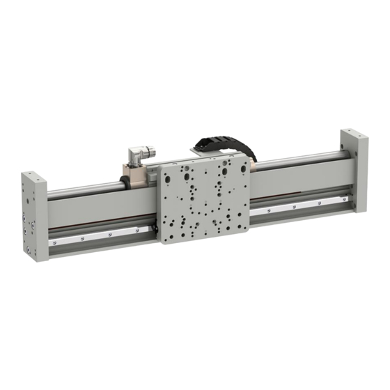
Option: External incremental sensor (sensor kit, stripe) LinMot® FM01 linear modules are moving stator applications with tubular linear motors for use in industrial and commercial installations. The mechanical design is based on a special aluminium profile on which up to two high-precision profile rail guides are attached. -
Page 8: Option External Sensor
The FM01 modules are available with two motor variants. Depending on the selected motor type, the modules have different mechanical values, which are listed below. The values for mass and friction are important for the configuration assistant of the LinMot-Talk software. …48x150G…... -
Page 9: Installation Instructions
The following sketches show examples of different installation options. The detailed dimensions can be found in the "Dimensions" chapter. 4.1.1 Installation Examples Example 1: Installation with “slider on the top” using side plates and brackets. NTI AG / LinMot FM01-48 Page 9 / 41... - Page 10 Example 3: “On the back” using end plates (lengths up to 1200 mm, only cross table x-axis trailing chain). Ordering information Item Description Item-No. Nut N8/M4 Nut for 8 mm T-slots with M4 thread 0150-2189 Nut N8/M6 Nut for 8 mm T-slots with M6 thread 0150-2558 Page 10 / 41 FM01-48 NTI AG / LinMot...
-
Page 11: Installation Of The Load
Before performing installation of the load, all necessary precautions must be taken to prevent operation of this device, e.g. the device must be disconnected from the power supply. 4.2.1 Mounting Plate FM01…48x150G… NTI AG / LinMot FM01-48 Page 11 / 41... -
Page 12: Mounting Plate Fm01
Installation Guide Linear Modules 4.2.2 Mounting Plate FM01…48x240F… Page 12 / 41 FM01-48 NTI AG / LinMot... -
Page 13: Electrical Connection
Only connect or disconnect the motor connector and sensor cable if no voltage is applied to the servo drive! Only original LinMot cables may be used for wiring the motor and sensor! Even assembled cables may only be manufactured from the original LinMot accessories and... -
Page 14: Start-Up
6.2 Setting the Parameters Logged into the drive, you will find all the parameters to be set in the LinMot-Talk’s software motor wizard. You can find the necessary information such as moving mass and friction of the carriage kits in the chapter Technical Data . -
Page 15: Accessories
Trailing Chain Kit for FM01-48 (0150-5668, 0150-5669, 0150-5328, 0150- 0150-5235 5329, 0150-5348, 0150-5349) FM01-TC2200-48x18 Trailing Chain Kit for FM01-48 (0150-5670, 0150-5330, 0150-5555) 0150-6550 FM01-TC2400-48x18 Trailing Chain Kit for FM01-48 (0150-5671, 0150-5331, 0150-5556) 0150-6551 7.1.1 Trailing Chain Dimensions NTI AG / LinMot FM01-48 Page 15 / 41... -
Page 16: Overview Trailing Chain Kit
7.1.2 Overview Trailing Chain Kit Item Trailing chain angle plate Trailing chain Trailing chain L-profile Socket pan head screws ISO14583 M3x6 Socket pan head screws ISO 4762 M4x10 Socket pan washer screws M4x10 Nut N8/M4 Page 16 / 41 FM01-48 NTI AG / LinMot... -
Page 17: Assembling Instructions (Cable Exit To The Left - Default)
3. Put cable into the trailing chain and mount the trailing chain onto both plates, use screw-locking compound. Connect the cable to the connector on the adapter. NTI AG / LinMot FM01-48 Page 17 / 41... - Page 18 The stator must be able to achieve the full required mechanical stroke. 5. Fix the cable on both sides onto trailing chain using cable ties. Page 18 / 41 FM01-48 NTI AG / LinMot...
-
Page 19: Motor Cables
Trailing Chain Cable W/C, 4 m 0150-1807 KS10-W/C-6 Trailing Chain Cable W/C, 6 m 0150-1858 KS10-W/C-8 Trailing Chain Cable W/C, 8 m 0150-1808 KS10-W/C- Trailing Chain Cable W/C, Custom length 0150-3139 NTI AG / LinMot FM01-48 Page 19 / 41... -
Page 20: Motor Cables For Indirect Wiring With Fixed Extension Cable
Motor Cable W/C, 2 m 0150-1811 K15-W/C-4 Motor Cable W/C, 4 m 0150-1801 K15-W/C-6 Motor Cable W/C, 6 m 0150-1802 K15-W/C-8 Motor Cable W/C, 8 m 0150-1803 K15-W/C- Motor Cable W/C, Custom length 0150-3131 Page 20 / 41 FM01-48 NTI AG / LinMot... -
Page 21: External Sensor
7.3.1 Overview Sensor Kit (Incremental) Pos. Item Magnet sensor MS01-1/D Sensor adapter M2.5x16 / ISO 7046-2 M2.5x10 / ISO 14583 Cable clamp (not pictured) M2.5x6 / ISO 7046-2 (not pictured) NTI AG / LinMot FM01-48 Page 21 / 41... -
Page 22: Dimensions
Installation Guide Linear Modules 7.3.2 Dimensions 7.3.3 Magnetic Strips for Incremental Sensor Carrier strip Magnetic band Page 22 / 41 FM01-48 NTI AG / LinMot... -
Page 23: Extender Incremental Sensor Cable
5330, 0150-5555) incremental F01-MB2450 Magnetic strip for E/F-Guide (Item-No. 0150-5671, 0150- 2430 (95.66) 0150-5468 5331, 0150-5556) incremental 7.3.4 Extender Incremental Sensor Cable Item Description Item-No. KS025-D15/D-Encoder Encoder Cable, High Flex, Custom length 0150-3168 NTI AG / LinMot FM01-48 Page 23 / 41... -
Page 24: Maintenance
7.4.1 Overview Sensor Kit (Absolute Sensor SSI) Pos. Item Magnet sensor MS01-1/D-SSI Sensor adapter M2.5x16 / ISO 7046-2 M2.5x10 / ISO 14583 Cable clamp (not pictured) M2.5x6 / ISO 7046-2 (not pictured) Page 24 / 41 FM01-48 NTI AG / LinMot... - Page 25 Installation Guide Linear Modules 7.4.2 Dimensions 7.4.3 Magnetic Strips for Absolute Sensor SSI Adhesive tape Carrier strip Magnetic band NTI AG / LinMot FM01-48 Page 25 / 41...
- Page 26 KSS01-12-D15/ABS-ENC- for MS01-1/D-SSI, Custom length 0150-3652 7.5 Absolute Sensor BiSS BiSS absolute sensor kit consists of external sensor, mounting brackets and screws. Magnetic strip and additional cables must be ordered separately. Page 26 / 41 FM01-48 NTI AG / LinMot...
- Page 27 Magnetic strip for E/F-Guide (absolute) 2190 (86.22) 0150-4924 MB01-ABS/BiSS-243 Magnetic strip for E/F-Guide (absolute) 2430 (95.67) 0150-4925 7.5.2 Absolute Sensor BiSS Cables Item Description Item-No. KSS01-12-D15/ABS-ENC- For MS01-1/D-SSI/BiSS, Custom length 0150-3652 NTI AG / LinMot FM01-48 Page 27 / 41...
-
Page 28: Maintenance Cycles
8.2 Inspection When inspecting, the following points must be checked: a) Visual inspection of lubrication grease level (clean and re-lubricate if necessary) b) Visual inspection of all wearing parts (replace if necessary) Page 28 / 41 FM01-48 NTI AG / LinMot... -
Page 29: Cleaning And Lubrication
Remove any excessive grease while moving the stator. The EM modules can normally be cleaned and lubricated without disassembly. Complete disassembly is only to be carried out by NTI AG / LinMot or certified companies. If the linear module is completely disassembled by other companies/persons, a complete loss of warranty automatically comes into effect. -
Page 30: Storage, Transport, Installation Altitude
The air in the storage area must not contain any harmful gases. • The max. installation altitude is 4'000 m above sea level. From 1'000 m, derating of 1 °C per 100 m is to be considered for air cooling. Page 30 / 41 FM01-48 NTI AG / LinMot... -
Page 31: Dimensions & Weights
1995 (78.54) 2250 (88.58) 4598 (10.14) 27050 (59.64) HP-BE02-MD02-C … 2490_2235_1CF48x150G- 2235 (87.99) 2490 (98.03) 4598 (10.14) 29487 (65.01) HP-BE02-MD02-C Stroke, moving mass and total weight differ in multiple stators configuration. NTI AG / LinMot FM01-48 Page 31 / 41... -
Page 32: Fm01-48
1910 (75.20) 2250 (88.58) 5546 (12.23) 27993 (61.71) HP-BE02-MD02-C … 2490_2150_1CF48x240F- 2150 (84.65) 2490 (98.03) 5546 (12.23) 30430 (67.09) HP-BE02-MD02-C Stroke, moving mass and total weight differ in multiple stators configuration. Page 32 / 41 FM01-48 NTI AG / LinMot... -
Page 33: Side Plates
Installation Guide Linear Modules 10.2 Side Plates 10.2.1 FM01-48…48x150G… NTI AG / LinMot FM01-48 Page 33 / 41... -
Page 34: Fm01-48
Installation Guide Linear Modules 10.2.2 FM01-48…48x240F… Page 34 / 41 FM01-48 NTI AG / LinMot... -
Page 35: Carriage Kit Mounting Plate
Installation Guide Linear Modules 10.3 Carriage Kit Mounting Plate 10.3.1 FM01-48…48x150G… NTI AG / LinMot FM01-48 Page 35 / 41... -
Page 36: Fm01-48
Installation Guide Linear Modules 10.3.2 FM01-48…48x240F… Page 36 / 41 FM01-48 NTI AG / LinMot... -
Page 37: International Certificates
Installation Guide Linear Modules 11 International Certificates Europe See chapter “EU Declaration of Conformity CE-Marking” See chapter “UK Declaration of Conformity UKCA-Marking” IECEE Ref. Certif. Nr. CH-8521 CB SCHEME NTI AG / LinMot FM01-48 Page 37 / 41... - Page 38 Installation Guide Linear Modules Page 38 / 41 FM01-48 NTI AG / LinMot...
-
Page 39: Eu Declaration Of Conformity Ce-Marking
+41 (0)56 419 91 91 Fax: +41 (0)56 419 91 92 declares under sole responsibility the compliance of the products: • Linear modules with carriage series CF48x150-HP-BE02-MD01-C • Linear modules with carriage series CF48x150-HP-BE02-MD01-C-2S • Linear modules with carriage series CF48x150-HP-BE02-MD02-C •... -
Page 40: Declaration Of Conformity Ukca-Marking
+41 (0)56 419 91 91 Fax: +41 (0)56 419 91 92 declares under sole responsibility the compliance of the products: • Linear modules with carriage series CF48x150-HP-BE02-MD01-C • Linear modules with carriage series CF48x150-HP-BE02-MD01-C-2S • Linear modules with carriage series CF48x150-HP-BE02-MD02-C •... - Page 41 ALL LINEAR MOTION FROM A SINGLE SOURCE Europe / Asia Headquarters North / South America Headquarters NTI AG - LinMot & MagSpring LinMot USA Inc. Bodenaeckerstrasse 2 N1922 State Road 120, Unit 1 CH-8957 Spreitenbach Lake Geneva, WI 53147 Switzerland Sales / Administration: +41 56 419 91 91 Sales / Administration: 262.743.2555...
Need help?
Do you have a question about the CF48x150-HP-BE02-MD01-C and is the answer not in the manual?
Questions and answers