
Related Manuals for LinMot EM01-48


Summary of Contents for LinMot EM01-48
- Page 1 Installation Guide Linear Modules EM01-48 NTI AG / LinMot Dok-Nr. 0185-0173-E_1V1_IG_Linear_Guides_EM01-48...
-
Page 2: Table Of Contents
Installation of the Load ........................10 Electrical Connection ..........................11 Motor Cable ............................. 11 C-Connector Wiring ......................... 11 Start-up ..............................12 LinMot Drive Setup .......................... 12 Setting the Parameters ........................12 6.2.1 Defining Payload .......................... 12 6.2.2 PID Controller ..........................12 6.2.3... - Page 3 EM01-48-xxx_xxx_1CE48x150G-HP ....................27 10.2 EM01-48-xxx_xxx_1CE48x240F-HP ....................28 10.3 End Plates............................29 10.4 Mounting Plate EM01-48-xxx_xxx_1CE48x150G-HP ..............30 10.5 Mounting Plate EM01-48-xxx_xxx_1CE48x240F-HP ..............31 International Certificates ........................32 EU Declaration of Conformity CE-Marking ..................34 UK Declaration of Conformity UKCA-Marking ................35...
-
Page 4: General Information
1.4 Liability NTI AG (as manufacturer of LinMot and MagSpring products) excludes all liability for damages and expenses caused by incorrect use of the products. This also applies to false applications, which are caused by NTI AG's own data and notes, for example in the course of sales, support or application activities. -
Page 5: Safety Instructions
Before working, make sure that there are no high voltages. Fast-moving Machine Parts The sliders of LinMot linear motors are fast-moving machine parts. All necessary precautions must be taken to prevent persons approaching the moving elements during operation (provide covers, guards, etc.). - Page 6 Linear motor sliders consist of a high-precision, thin-walled stainless steel tube in which the neodymium magnets are housed. The LinMot sliders should be handled with care. Avoid contact with other sliders or iron parts as this can damage the magnets and the slider surface.
-
Page 7: Intended Use
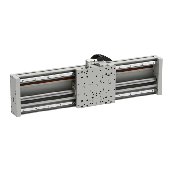
Option: External Sensor (Sensor Kit, Stripe) LinMot EM01 linear modules are moving stator applications with tubular linear motors for use in industrial and commercial installations. The mechanical design is based on a special aluminium profile on which up to two high-precision profile rail guides are attached. Use of ball bearings in the carriages guarantee a reliable and smooth operation, support of external forces, torques and bending moments. -
Page 8: Option External Sensor
It is also possible to run multiple stators on the same guide. Direct mechanical compatibility with other LinMot linear modules for the vertical axis, linear rotary motors and other products, combined with the wide range of stroke availabilities for all axes, the moving stator guides offer a powerful toolbox for any automation task. -
Page 9: Installation Instructions
Example 1: Installation with “slider on the top” using end plates and brackets. Example 2: Installation with “slider on the top” using T-Nuts from the bottom of the profile. Example 3: Installation “on the back” using end plates (lengths up to 1200 mm). NTI AG / LinMot EM01-48 Page 9 / 36... -
Page 10: Installation Of The Load
Before performing installation of the load, all necessary precautions must be taken to prevent operation of this device, e. g. the device must be disconnected from the power supply. Page 10 / 36 EM01-48 NTI AG / LinMot... -
Page 11: Electrical Connection
Only connect or disconnect the motor connector and sensor cable if no voltage is applied to the servo drive! Only original LinMot cables may be used for wiring the motor and sensor! Even assembled cables may only be manufactured from the original LinMot accessories and... -
Page 12: Start-Up
6.2 Setting the Parameters Logged into the drive, you will find all the parameters to be set in the LinMot-Talk’s software motor wizard. You can find the necessary information such as moving mass and friction of the carriage kits in the chapter Technical Data Carriage Kit. -
Page 13: Accessories
7 Accessories 7.1 Trailing Chain Kits Item Description Item-No. EM01-TC300-48x18 Trailing Chain Kit for EM01-48 (Trailing chain, brackets, srews) 0150-4812 EM01-TC400-48x18 Trailing Chain Kit for EM01-48 (Trailing chain, brackets, srews) 0150-4813 EM01-TC500-48x18 Trailing Chain Kit for EM01-48 (Trailing chain, brackets, srews) -
Page 14: Overview Trailing Chain Kit
Item Trailing chain Trailing chain angle plate Socket pan head screws ISO14583 M3x6 Socket pan head screws ISO14583 M4x8 Nut N8/M4 Trailing chain L-Profile Socket pan washer screws BN 5128 M4x10 Page 14 / 36 EM01-48 NTI AG / LinMot... -
Page 15: Assembling Instructions
Nuts. Longer lower angled plates have in the centre an additional mounting point. 3. Put cable into the trailing chain and mount the trailing chain onto both plates, use screw-locking compound. NTI AG / LinMot EM01-48 Page 15 / 36... - Page 16 5. Fix the cable on both sides onto trailing chain using cable ties. Upper end of trailing chain Lower end of trailing chain Page 16 / 36 EM01-48 NTI AG / LinMot...
-
Page 17: Motor Cables
Trailing Chain Cable W/C, 4 m 0150-1807 KS10-W/C-6 Trailing Chain Cable W/C, 6 m 0150-1858 KS10-W/C-8 Trailing Chain Cable W/C, 8 m 0150-1808 KS10-W/C- Trailing Chain Cable W/C, Custom length 0150-3139 NTI AG / LinMot EM01-48 Page 17 / 36... -
Page 18: Motor Cables For Indirect Wiring With Fixed Extension Cable
Motor Cable W/C, 2 m 0150-1811 K15-W/C-4 Motor Cable W/C, 4 m 0150-1801 K15-W/C-6 Motor Cable W/C, 6 m 0150-1802 K15-W/C-8 Motor Cable W/C, 8 m 0150-1803 K15-W/C- Motor Cable W/C, Custom length 0150-3131 Page 18 / 36 EM01-48 NTI AG / LinMot... -
Page 19: External Sensor
7.3.1 Overview Incremental External Sensor Kit Pos. Item Magnet sensor MS01-1/D Sensor adapter M2.5x16 / ISO 7046-2 M2.5x10 / ISO 14583 Cable clamp (not pictured) M2.5x6 / ISO 7046-2 (not pictured) NTI AG / LinMot EM01-48 Page 19 / 36... -
Page 20: Dimensions
Installation Guide Linear Modules 7.3.2 Dimensions 7.3.3 Magnetic Strips for Incremental External Sensor Carrier strip Magnetic band Page 20 / 36 EM01-48 NTI AG / LinMot... -
Page 21: Extender Incremental Sensor Cable
7.4 Absolute External Sensor Kit External sensor kit consists of external sensor, mounting brackets and screws. Magnetic strip and cables must be ordered separately. Item Description Item-No. EM01-37S-SK/D-SSI External Sensor kit for EM-Module (absolute) 0150-2943 NTI AG / LinMot EM01-48 Page 21 / 36... -
Page 22: Overview Absolute External Sensor Kit
7.4.1 Overview Absolute External Sensor Kit Pos. Item Magnet sensor MS01-1/D-SSI Sensor adapter M2.5x16 / ISO 7046-2 M2.5x10 / ISO 14583 Cable clamp (not pictured) M2.5x6 / ISO 7046-2 (not pictured) 7.4.2 Dimensions Page 22 / 36 EM01-48 NTI AG / LinMot... -
Page 23: Magnetic Strips For Absolute External Sensor
Magnetic strip for EM-Module (absolute) 1120 (44.09) 0150-2966 EM01-MB1400/D-SSI Magnetic strip for EM-Module (absolute) 1320 (51.97) 0150-2967 EM01-MB1600/D-SSI Magnetic strip for EM-Module (absolute) 1520 (59.84) 0150-2968 EM01-MB2000/D-SSI Magnetic strip for EM-Module (absolute) 1920 (75.59) 0150-2969 NTI AG / LinMot EM01-48 Page 23 / 36... -
Page 24: Absolute External Sensor Cables
Installation Guide Linear Modules 7.4.4 Absolute External Sensor Cables Item Description Item-No. KSS01-12.../ABS-ENC-10 for MS01-1/D-SSI, 10m, flying leads 0160-3387 KSS01-12-D15/ABS-ENC- for MS01-1/D-SSI, Custom length 0150-3652 Page 24 / 36 EM01-48 NTI AG / LinMot... -
Page 25: Maintenance
3. Move the carriage kit three times over the entire stroke. Remove any excessive grease and soil while moving the carriage kit. 4. If no lubricating film is visible on the rail, repeat step 2 and 3. NTI AG / LinMot EM01-48 Page 25 / 36... -
Page 26: Linear Motor (Stator And Slider) Cleaning And Lubrication
The air in the storage area must not contain any harmful gases. • The max. installation altitude is 4'000 m above sea level. From 1'000 m, derating of 1 °C per 100 m is to be considered for air cooling. Page 26 / 36 EM01-48 NTI AG / LinMot... -
Page 27: Dimensions & Weights
Installation Guide Linear Modules 10 Dimensions & Weights 10.1 EM01-48-xxx_xxx_1CE48x150G-HP Linear Module EM01-48… Stroke H Length L Moving mass Total weight [mm (inch)] [mm (inch)] [g (lb)] [g (lb)] …-380_145_1CE48x150G-HP-BE02-MD01-C 145 (5.71) 380 (14.96) 5280 (11.64) 11178 (24.64) …-440_205_1CE48x150G-HP-BE02-MD01-C 205 (8.07) 440 (17.32) -
Page 28: Em01-48-Xxx_Xxx_1Ce48X240F-Hp
Installation Guide Linear Modules 10.2 EM01-48-xxx_xxx_1CE48x240F-HP Linear Module EM01-48… Stroke H Length L Moving mass Total weight [mm (inch)] [mm (inch)] [g (lb)] [g (lb)] …-440_115_1CE48x240F-HP-BE02-MD01-C 115 (4.53) 440 (17.32) 7730 (17.04) 14331 (31.59) …-530_205_1CE48x240F-HP-BE02-MD01-C 205 (8.07) 530 (20.87) 7730 (17.04) 15666 (34.54) -
Page 29: End Plates
Installation Guide Linear Modules 10.3 End Plates NTI AG / LinMot EM01-48 Page 29 / 36... -
Page 30: Mounting Plate Em01-48-Xxx_Xxx_1Ce48X150G-Hp
Installation Guide Linear Modules 10.4 Mounting Plate EM01-48-xxx_xxx_1CE48x150G-HP Page 30 / 36 EM01-48 NTI AG / LinMot... -
Page 31: Mounting Plate Em01-48-Xxx_Xxx_1Ce48X240F-Hp
Installation Guide Linear Modules 10.5 Mounting Plate EM01-48-xxx_xxx_1CE48x240F-HP NTI AG / LinMot EM01-48 Page 31 / 36... -
Page 32: International Certificates
Installation Guide Linear Modules 11 International Certificates Europe See chapter “EU Declaration of Conformity CE-Marking” See chapter “UK Declaration of Conformity UKCA-Marking” IECEE Ref. Certif. Nr. CH-8521 CB SCHEME Page 32 / 36 EM01-48 NTI AG / LinMot... - Page 33 Installation Guide Linear Modules NTI AG / LinMot EM01-48 Page 33 / 36...
-
Page 34: Eu Declaration Of Conformity Ce-Marking
Installation Guide Linear Modules 12 EU Declaration of Conformity CE-Marking NTI AG / LinMot ® Bodenaeckerstrasse 2 8957 Spreitenbach Switzerland Tel.: +41 (0)56 419 91 91 Fax: +41 (0)56 419 91 92 declares under sole responsibility the compliance of the products: •... -
Page 35: Declaration Of Conformity Ukca-Marking
Installation Guide Linear Modules 13 UK Declaration of Conformity UKCA-Marking NTI AG / LinMot ® Bodenaeckerstrasse 2 8957 Spreitenbach Switzerland Tel.: +41 (0)56 419 91 91 Fax: +41 (0)56 419 91 92 declares under sole responsibility the compliance of the products: •... - Page 36 ALL LINEAR MOTION FROM A SINGLE SOURCE Europe / Asia Headquarters North / South America Headquarters NTI AG - LinMot & MagSpring LinMot USA Inc. Bodenaeckerstrasse 2 N1922 State Road 120, Unit 1 CH-8957 Spreitenbach Lake Geneva, WI 53147 Switzerland Sales / Administration: +41 56 419 91 91 Sales / Administration: 262.743.2555...
Need help?
Do you have a question about the EM01-48 and is the answer not in the manual?
Questions and answers