
Subscribe to Our Youtube Channel
Related Manuals for HYDAC International OLFCM-5/15


Summary of Contents for HYDAC International OLFCM-5/15
- Page 1 OffLine Filter OLFCM-5/15 OLFCM-10/15 Installation instructions 3573893c / 2024-05...
- Page 2 Translation / original language: German © 2024 HYDAC Filter Systems GmbH. All rights reserved. ® All product names used may be trademarks or registered trademarks of HYDAC or the particular owner. This manual was prepared to the best of our knowledge. Nevertheless and despite the greatest care, it cannot be excluded that mistakes could have crept in.
-
Page 3: Table Of Contents
Checking the scope of supply................Decoding the type label ..................3.4.1 Model code ................... Technical data ....................Dimensions/hydraulic diagram ................3.6.1 Drawing OLFCM-5/15-T-… / OLFCM-10/15-T-… ........ 3.6.1.1 Components OLFCM-5-T… / OLFCM-10-T…....Transportation/storage ....................Mounting/installing ......................Avoiding siphoning ..................... Measuring dynamic pressure or differential pressure......... - Page 4 CONTENTS Connecting AquaSensor to an evaluation unit (optional) ........Taking the filter unit into operation ..............Checking installation................... Operation ........................Observing the optical clogging indicator (optional)..........Rectifying malfunctions ....................Performing maintenance ....................Maintenance table ....................Resetting visual clogging indicator VM x BM.x........... Changing filter element –...
-
Page 5: General
1. GENERAL General 45035996988833419 Before you use this product for the first time, read this manual at least up to the chapter "Operation". If you would like to carry out maintenance or troubleshooting, you can find the procedure in the respective chapters. The use and the handling of the product as well as its use are not self-explanatory and are described in detail in this manual. - Page 6 1. GENERAL Warnings visually highlighted in boxes Warnings visually highlighted in boxes provide the following information in relation to a danger: DANGER High electrical voltages Life-threatening injuries or death! Disconnect system from power supply and secure it against being started up again. Warning level Type and source of danger How high is the risk...
-
Page 7: Representation Of Requirements
1. GENERAL Warning level What this means for you Warns of dangers for persons with high risk potential. DANGER Failure to observe this warning will most probably result in serious injury or even death. Warns of dangers for persons with medium risk potential. WARNING Failure to observe this warning may result in serious injury or even death. -
Page 8: Representation Of Intermediate Results/Results
1. GENERAL 1.2.4 Representation of intermediate results/results 9007199396760075 In the case of some activities, it is necessary to carry out work steps with intermediate results and end results. Intermediate results are the consequence of activities; they are marked with an indented arrow. -
Page 9: Safety Regulations
2. SAFETY REGULATIONS Safety regulations 9007199426696203 The product is designed as safe. In spite of that, there is danger in some actions that can only be avoided by using the right procedures. These correct procedures and points, which must be followed, are described in this manual. - Page 10 2. SAFETY REGULATIONS Exposed electrical components Danger due to operating pressure Signs used for the required specialist personnel These symbols show the required training/knowledge for installation work and/or main- tenance work. Specialist personnel – Electrical These persons have specific specialist training and several years of work experience.
-
Page 11: Danger Notifications
2. SAFETY REGULATIONS Danger notifications 9007199575938955 The following residual risks can occur in the various life phases of the product: Life phase – in all the life phases. The following risks could arise during all Life phases: Environmental tip Siphoning effect Reservoir overflowing/leaking = oil spill Remove the ends of the hoses from the reservoir after operation or shut the shut-off device in the suction line. -
Page 12: Observing Regulatory Information
2. SAFETY REGULATIONS Observing regulatory information 9007199302626571 Observe the following regulatory information and directives: ● Legal and local regulations for accident prevention ● Legal and local regulations for environmental protection and environmental require- ments ● Country-specific regulations, organisation-specific regulations ● Occupational safety rules Observing environmental precautions 45035996541652875... -
Page 13: Product And Technical Specifications
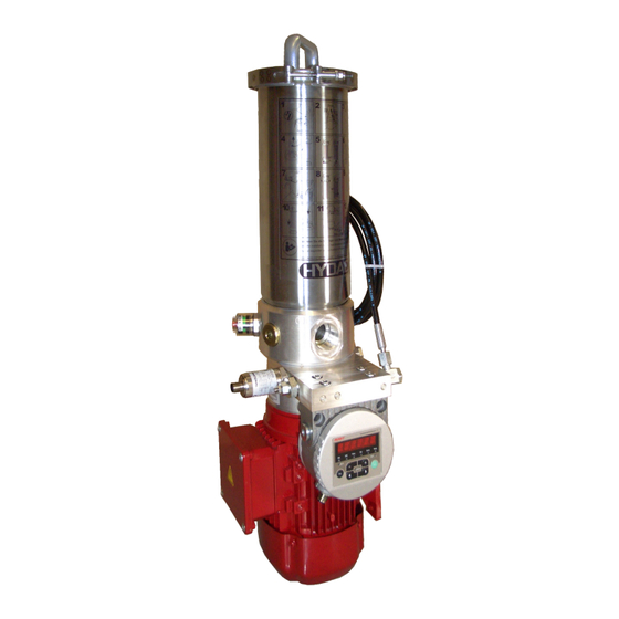
3. PRODUCT AND TECHNICAL SPECIFICATIONS Product and technical specifications 9007199318039307 The filter units of the OLF-5 and OLF-10 series are used for fine filtration of hydraulic oils in the bypass flow. The series includes numerous versions, e.g. with or without motor-pump unit, element removal upwards or downwards, tank installation variant, optionally with integrated Condition Monitoring to determine fluid purity and water content, etc. -
Page 14: Improper Use Or Use Deviating From Intended Use
3. PRODUCT AND TECHNICAL SPECIFICATIONS Improper use or use deviating from intended use 9007199321210123 DANGER Danger due to unintended use Bodily injury and damage to property Never operate the filter unit in potentially explosive atmospheres. Use the filter unit only with the permitted operating media. Any other use or extended use shall not be considered intended use. -
Page 15: Decoding The Type Label
3. PRODUCT AND TECHNICAL SPECIFICATIONS Decoding the type label 9007199317864331 Details for identifying the product are found on the name plates on the product as well as their components. Always mention the part number and the serial number when contacting HYDAC. Fig. 3: Decoding the model code Item Description... -
Page 16: Model Code
3. PRODUCT AND TECHNICAL SPECIFICATIONS 3.4.1 Model code 9007199320254475 The filter unit/filter housing is defined by the following model code: OLFCM - 5/15 - T - xxx-x - NxXMxxx - xx Basic type OLFCM = OffLine Filter ConditionMonitoring Size / flow rate 5/15 = 15 l/min 10/15 = 15 l/min Version... -
Page 17: Dimensions/Hydraulic Diagram
3. PRODUCT AND TECHNICAL SPECIFICATIONS Empty weight See type label Filtration rating ß(2) > 1000 (∆p 2.5 bar) with N5DMxxx or N10DMxxx filter element Voltage supply / power consumption See the type label on the electric motor Emission sound pressure level L < 70 dB(A) Design service life If the service and maintenance intervals are followed, the intended service life of the unit is not limited. -
Page 18: Drawing Olfcm-5/15-T
3. PRODUCT AND TECHNICAL SPECIFICATIONS 3.6.1 Drawing OLFCM-5/15-T-… / OLFCM-10/15-T-… 9007199332746379 The filtration unit has the following dimensions: Fig. 5: Drawing 3486357 – OLFCM-5/15 / OLFCM-10/15 All unit dimensions in mm. 18 / 52 3573893c / 2024-05... - Page 19 3. PRODUCT AND TECHNICAL SPECIFICATIONS Item Designation Fluid inlet Fluid outlet DRAIN Emptying / fluid drain AIR BLEED Venting / air vent Clogging indicator Required space for removing the filter element Space required for cooling the electric motor 19 / 52 3573893c / 2024-05...
-
Page 20: Components Olfcm-5-T
3. PRODUCT AND TECHNICAL SPECIFICATIONS 3.6.1.1 Components OLFCM-5-T… / OLFCM-10-T… 78046347 The filter unit has the following components: Fig. 6: Components OLFCM-5-T… / OLFCM-10-T… 20 / 52 3573893c / 2024-05... - Page 21 3. PRODUCT AND TECHNICAL SPECIFICATIONS Item Designation Fluid inlet Fluid outlet AIR BLEED Venting / air vent DRAIN Emptying / fluid drain Clogging indicator Electric motor Fan cover Terminal box Mounting foot / electric motor foot Filter bowl Clamping clip Filter bowl cover 21 / 52 3573893c / 2024-05...
-
Page 22: Transportation/Storage
4. TRANSPORTATION/STORAGE Transportation/storage 9007199317989771 Empty the filter unit/filter housing fully before transporting it or putting it into storage. Remove the used filter element/filter cartridge and clean the inside of the filter housing. NOTICE Do not pick up the product by the clogging indicator The clogging indicator is damaged/destroyed. -
Page 23: Mounting/Installing
5. MOUNTING/INSTALLING Mounting/installing 27021597827669003 An optimally assembled and installed product ensures a safe and continuous operation. Below, you will find information on how to install and connect the filter unit hydrauli- cally and electrically. Only install the filter unit vertically. Fasten the filter unit to the mounting foot or the foot on the electric motor using four suitable screws, depending on the version. -
Page 24: Avoiding Siphoning
5. MOUNTING/INSTALLING Avoiding siphoning 72057594101524491 If there is a height difference ΔH between the suction side and pressure side container/system, the low lying line can develop a suction effect and trigger the siphoning effect between the communicating containers/ systems. This siphoning effect also occurs when fluid is pumped in a pre-pressurised container. -
Page 25: Measuring Dynamic Pressure Or Differential Pressure
5. MOUNTING/INSTALLING Measuring dynamic pressure or differential pressure 54043195669075979 If pressure is measured in a hydraulic system, the type of measurement such as dynamic pressure or differential pressure as well as the measurement point MP is critical, as shown in the following figure. Fig. 9: Measuring dynamic pressure or differential pressure Measurement point ∑∆p... -
Page 26: Hydraulic Connection
5. MOUNTING/INSTALLING Hydraulic connection 513627531 Observe the following instructions for hydraulic installation. 5.3.1 Calculating the drop off load 536696459 Install the unit securely in a hydraulic system, take the drop-off load into account with the piping or hose system. You will find the respective formula to calculate the drop off load. -
Page 27: Connecting Inlet In
5. MOUNTING/INSTALLING 5.3.2 Connecting inlet IN 9007199318417419 Use a suitable screwed fitting for the connection. Please note when connecting the filter unit: 1. Connect the filter unit to the hydraulic system with a suitable port. 2. For the suction port, ensure that the feed-line is suitable for a negative pressure of ≥ -0.5 bar and that the permitted pressure is not exceeded. -
Page 28: Connecting Electric Motor, 1-Phase
5. MOUNTING/INSTALLING DANGER Electric voltage warning Danger of fatal injury In case of any damage to the insulation, switch off the supply voltage immediately and arrange for repairs to be carried out. Before carrying out any work on the electrical system and before any mainte- nance, cleaning or repair work, disconnect the feed line or pull out the power plug. -
Page 29: Connecting Electrical Clogging Indicator
5. MOUNTING/INSTALLING Connecting electrical clogging indicator 72057594101610123 If the filter housing / filter unit is equipped with an electrical clogging indicator, connect it to your control centre according to the switching logic. For details, see ▶Sec. 9.3 "Clogging indicators – characteristics". Connecting ContaminationSensor to voltage 18014398587610251 Connect the ContaminationSensor... -
Page 30: Operation
6. OPERATION Operation 27021597830749963 To monitor the service life of the filter element / filter cartridge during operation, the filter unit / filter housing can be equipped with a clogging indicator (back pressure / differ- ential pressure, optical or electrical). Check the visual clogging indicator daily, for details see ▶Sec. 6.1 "Observing the optical clogging indicator (optional)"... -
Page 31: Rectifying Malfunctions
7. RECTIFYING MALFUNCTIONS Rectifying malfunctions 9007199319665547 In order to get quick and immediate assistance in the case of errors, you will find the most often occurring errors with their cause and remedy with suitable specialist personnel in this chapter. The following errors may occur during handling or operation of the filter unit / filter housing: Fault Cause(s) - Page 32 7. RECTIFYING MALFUNCTIONS Fault Cause(s) Remedy The running noise of The protective screen Clean the protective the motor-pump is clogged. screen. assembly becomes substantially louder. The pump does not There is no oil in the Prime the pump via the draw effectively or not pump.
-
Page 33: Performing Maintenance
8. PERFORMING MAINTENANCE Performing maintenance 9007199318833547 This chapter contains the description of the required maintenance activities and the qualifications of the staff needed to carry out these tasks. WARNING The hydraulic system is under operating pressure Danger of bodily injury The hydraulic system must be depressurised before performing any work on it. -
Page 34: Resetting Visual Clogging Indicator Vm X Bm.x
8. PERFORMING MAINTENANCE Resetting visual clogging indicator VM x BM.x 9007199318989195 The visual clogging indicator VM x BM.x has a manual reset. Reset the visual clogging indicator manually after each filter element change, as shown below. ü The filter element has been replaced. 1. - Page 35 8. PERFORMING MAINTENANCE 2. Provide a suitable container to collect DRAIN any leaking operating fluid. The capacity depends on the size and is ≈ 3 litres for size 5 and ≈ 6 litres for size 10. Empty the filter housing using the drain screw DRAIN = 10 mm.
- Page 36 AIR BLEED 8. PERFORMING MAINTENANCE 5. Loosen the dirt collecting basket by turning it ≈ 30° clockwise. AIR BLEED ≈ 30° 6. Remove the filter element from the filter housing cover by turning it ≈ 30° clockwise, and dispose of it in an envi- ronmentally friendly manner.
- Page 37 8. PERFORMING MAINTENANCE 7. Clean the inside of the filter housing to remove dirt and deposits. 8. Check the O-ring on the filter bowl for damage. Replace it if necessary. Slightly wet the O-rings on the filter bowl cover and on the filter element with the operating medium.
- Page 38 AIR BLEED 8. PERFORMING MAINTENANCE 10. Attach the dirt collection bowl to the bottom of the filter element by turning it ≈ 30° counterclockwise. ≈ 30° AIR BLEED 11. Place the filter element with filter bowl cover and dirt collection container in the filter housing.
-
Page 39: Changing The Protective Screen
8. PERFORMING MAINTENANCE 15. Tighten the drain screw DRAIN DRAIN = 10 mm. 16. Switch on the filter unit/hydraulic system and bleed the filter housing via the bleed screw AIR BLEED = 6 mm in the filter bowl cover. AIR BLEED 17. Put the unit into operation and check the filter unit/filter unit for leaks. -
Page 40: Annex
9. ANNEX Annex 9007199767907979 This Annex contains additional information on the product. Finding spare parts/accessories 9007199319667851 Use only original spare parts for a long and defect-free life cycle of the product. When ordering spare parts and accessories make sure to always indicate the exact model code and the serial number. -
Page 41: Spare Part Drawing Olfcm-X/Xx-T
9. ANNEX 9.1.2 Spare part drawing OLFCM-x/xx-T-... Toploader 9007199445339787 The following drawing shows the individual parts of the OLFCM-x/xx-T-…: Fig. 14: Spare parts OLFCM-x/xx-T - 32522084 41 / 52 3573893c / 2024-05... -
Page 42: Accessories - Tank Connection Kit Olf-5-Tak
9. ANNEX 9.1.3 Accessories – tank connection kit OLF-5-TAK 9007199320230795 The tank connection kit TAK is used for quick and easy retrofitting of an OLF filter unit to existing hydraulic systems. This can be inserted in all hydraulic systems with a breather filter in accordance with the connection diagram DIN 24557/T2. -
Page 43: Contacting Customer Service
9. ANNEX Contacting Customer Service 72057594095185931 Contact details such as the telephone numbers, e-mail and mailing addresses for the Hotline, product support, Customer Service, branch offices, service partners for mainte- nance, repair and spare parts can be found on our homepage www.hydac.com. HYDAC SYSTEMS &... - Page 44 9. ANNEX Display type Visual display with green-red field, auto- matic return Weight 55 g Response pressure or indication range VM 2 B.x = 2 bar -10% VM 3 B.x = 3 bar -10% VM 5 B.x = 5 bar -10% VM 8 B.x = 8 bar ±10% Permitted operating pressure ≤ 210 bar Permitted temperature range -30 … +100 °C Connector thread G ½ Required installation space According to HN 28-22 Maximum tightening torque...
-
Page 45: Differential Pressure Indicator, Visual - Vm X Bm.x
9. ANNEX 9.3.2 Differential pressure indicator, visual – VM x BM.x 27021597953743627 The visual differential pressure indicator reacts to the increasing pressure difference as the contamination level of the filter element increases. Fig. 17: Differential pressure indicator, visual VM x BM.x Display type Visual display with green-red field, manual return Weight 55 g... -
Page 46: Differential Pressure Indicator, Electrical - Vm X C.x
9. ANNEX 9.3.3 Differential pressure indicator, electrical – VM x C.x 27021597953870731 The electrical differential pressure indicator reacts to the increasing pressure difference as the contamination level of the filter element increases. Fig. 18: Differential pressure indicator, electrical VM x C.x Display type Electrical switch Weight 120 g Response pressure or indication range... -
Page 47: Differential Pressure Indicator, Electrical - Vm X D.x /-L-Xx
9. ANNEX 9.3.4 Differential pressure indicator, electrical – VM x D.x /-L-xx 27021597953879435 The electrical differential pressure indicator reacts to the increasing pressure difference as the contamination level of the filter element increases. Fig. 19: Differential pressure indicator, electrical VM x D.x /-Lxx Display type Visual display and electrical switch Weight 150 g Response pressure or indication range... -
Page 48: Glossary
GLOSSARY Glossary AquaSensor AS1000 series class is displayed in accordance with either ISO/SAE or ISO/NAS. The latest materials and technologies, combined with proven techniques, ensure that users have a small and robust stationary sensor at their disposal. The attractive price- performance ratio makes it particularly interesting for OEM applications for Condition Monitoring... -
Page 49: Index
INDEX Index AquaSensor 29 Installation Connection IN 27 27 Checking direction of rotation Electric motor 28 Pump 28 Making the electrical connections Clogging indicator Checking the supply voltage 27 Differential pressure indicator Installing motor protection switch 27 44, 45, 46, 47 Observing the 30 Reset... - Page 50 50 / 52 3573893c / 2024-05...
- Page 51 51 / 52 3573893c / 2024-05...
- Page 52 HYDAC Filter Systems GmbH Industriegebiet 66280 Sulzbach/Saar Germany Tel. +49 6897 509-01 filtersystems@hydac.com www.hydac.com Further addresses: www.hydac.com/en/contacts...
Need help?
Do you have a question about the OLFCM-5/15 and is the answer not in the manual?
Questions and answers