Table of Contents
Advertisement
Quick Links
Advertisement
Chapters
Table of Contents

Subscribe to Our Youtube Channel
Related Manuals for HYDAC International MFU-10P


Summary of Contents for HYDAC International MFU-10P
- Page 1 MobileFiltration Unit MFU-10P Operating instructions 4391553e / 2023-07...
- Page 2 Translation / original language: English © 2023 HYDAC Filter Systems GmbH. All rights reserved. ® All product names used may be trademarks or registered trademarks of HYDAC or the particular owner. This manual was prepared to the best of our knowledge. Nevertheless and despite the greatest care, it is possible that it may contain errors.
-
Page 3: Table Of Contents
TABLE OF CONTENTS Table of Contents General ........................... Target group of the manual ................Illustrations in the manual................... 1.2.1 Show warning signs................1.2.2 Representation of requirements ............1.2.3 Representation of procedural instructions ..........1.2.4 Representation of intermediate results/results ........1.2.5 Supplementary symbols ............... -
Page 4: Fig. 25 Removing/Mounting The Push-In Protective Screen
TABLE OF CONTENTS Making the electrical connections............... 5.4.1 Filter unit without power plug/without connection cable ....... 5.4.2 Connecting the filter unit to 12 V DC or 24 V DC ......... 5.4.2.1 Connection with a 2-pin male connector ......5.4.3 Connecting a filter unit with a power plug for 120/230 V AC, single phase.................... - Page 5 TABLE OF CONTENTS 10.3 Declaration of conformity..................Glossary .......................... Index ..........................5 / 84 4391553e / 2023-07...
-
Page 6: General
1. GENERAL General 36028797734092427 Before you use this product for the first time, read this manual at least up to the chapter "Operation". If you would like to carry out maintenance or troubleshooting, you can find the procedure in the respective chapters. The use and the handling of the product as well as its use are not self-explanatory and are described in detail in this manual. - Page 7 1. GENERAL Read and observe the warnings carefully and follow the steps provided precisely. Warnings visually highlighted in boxes Warnings visually highlighted in boxes provide the following information in relation to a danger: DANGER High electrical voltages Life-threatening injuries or death! Disconnect system from power supply and secure it against being started up again.
-
Page 8: Representation Of Requirements
1. GENERAL Warning level What this means for you Warns of dangers for persons with high risk potential. DANGER Failure to observe this warning will most likely result in serious injury or even death. Warns of dangers for people with medium risk potential. WARNING Failure to observe this warning may result in serious injury or even death. -
Page 9: Representation Of Intermediate Results/Results
1. GENERAL 1.2.4 Representation of intermediate results/results 9007199396760075 In the case of some activities, it is necessary to carry out work steps with intermediate results and end results. Intermediate results are the consequence of activities; they are marked with an indented arrow. -
Page 10: Safety
2. SAFETY Safety 54043195788865547 The product is designed as safe. In spite of that, there is danger in some actions that can only be avoided by using the right procedures. These correct procedures and points, which must be followed, are described in this manual. - Page 11 2. SAFETY Activity Personnel Knowledge Commissioning Specialist Safe handling/use of tools. personnel - Product-specific knowledge is required. Mechanical Specialist personnel - Electrical Handling, Operating Product-specific knowledge is required. operation, personnel - Knowledge about handling the operating operation monitoring General fluid/operating medium is required Troubleshooting Mainte- Specialist Safe handling/use of tools.
-
Page 12: Hazard Symbols / Pictograms
2. SAFETY Hazard symbols / pictograms 72057594194920203 The following are the safety symbols / pictograms in this manual. They indicate specific dangers to persons, property or to the surroundings. Observe these safety symbols / pictograms and act with particular caution in such cases. Always keep all symbols / pictograms complete and legible. - Page 13 2. SAFETY Hazardous to the environment Others symbols used These marks can be found for all safety and warning instructions in this manual which indicate a particular danger to persons, property or the environment. Exposed electrical components Danger due to operating pressure Signs used for the required specialist personnel These symbols show the required training/knowledge for installation work and/or main- tenance work.
-
Page 14: Danger Notifications
2. SAFETY Danger notifications 54043195685369995 The following residual risks can occur in the various life phases of the product: Life phase – in all the life phases. The following risks could arise during all Life phases: DANGER Electric voltage warning Danger of fatal injury In case of any damage to the insulation, switch off the supply voltage immediately and arrange for repairs to be carried out. - Page 15 2. SAFETY NOTICE Operation without the protective screen The filter unit will be damaged/destroyed Always operate the filter unit with a protective screen. NOTICE Damaged protective screen The filter unit will be damaged/destroyed Never operate the filter unit with a damaged or defective protective screen. Only for the option with compressed air drive: 15 / 84 4391553e / 2023-07...
-
Page 16: Safety Marking
2. SAFETY Safety marking 36028797286950283 The following safety markings, labels / signs are provided on the product. The labels / signs on the product must always be easy to read. Fig. 1: Safety marking, label / sign on the product 1 Label Name plate with the manufacturer's address, for details, see ▶Sec. 3.5 "Decoding the name plate"... -
Page 17: Observing Regulatory Information
2. SAFETY Observing regulatory information 9007199302626571 Observe the following regulatory information and directives: ● Legal and local regulations for accident prevention ● Legal and local regulations for environmental protection and environmental require- ments ● Country-specific regulations, organization-specific regulations ● Occupational safety rules Observing environmental precautions 45035996541652875 Take all measures to protect the environment. -
Page 18: Product And Technical Specifications
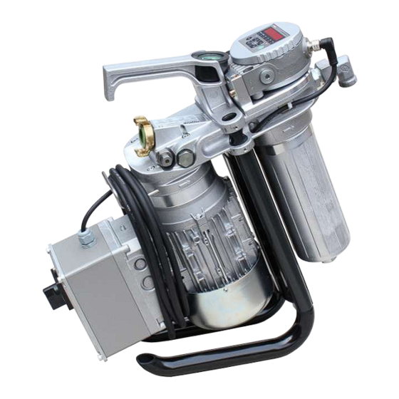
ISO, SAE or NAS. The supply voltage of the ContaminationSensor is available after switching on the filter unit. Follow the operating instructions included in the scope of delivery to operate the ContaminationSensor. Fig. 3: MFU-10P with ContaminationSensor 18 / 84 4391553e / 2023-07... -
Page 19: Checking The Scope Of Delivery
3. PRODUCT AND TECHNICAL SPECIFICATIONS Checking the scope of delivery 45035996354375435 Here you will find the scope of delivery for the product. ● Check the packaging and the product for damage. Report any damage in transit to the forwarding agent or the HYDAC department in charge. -
Page 20: Improper Use Or Use Deviating From Intended Use
3. PRODUCT AND TECHNICAL SPECIFICATIONS Improper use or use deviating from intended use 36028797097527819 Any other or extending use beyond this shall not be considered intended use. HYDAC FILTER SYSTEMS GMBH will assume no liability for any damage resulting from such use. This risk is borne solely by the owner. Improper use can result in hazards and/or the filter unit can be damaged. -
Page 21: Technical Data
54043195606644491 If you are aware of the technical data of the product, you will be able to use it optimally. This chapter provides the technical data of the product: MFU-10P Permitted operating fluids n Mineral oils in accordance with ISO 6743/4 DIN 51524... - Page 22 3. PRODUCT AND TECHNICAL SPECIFICATIONS MFU-10P Signal cable, length Emission sound pressure level L ≤ 65 db(A) Design service life If the service and maintenance intervals are followed, the intended service life of the unit is not limited. The IP protection class of the installed power plug could be different. See IEC DIN EN 60204-1, chapter 7.2.2.
-
Page 23: Decoding The Name Plate
3. PRODUCT AND TECHNICAL SPECIFICATIONS Decoding the name plate 45035996354390283 Details for identifying the product are found on the name plates on the product as well as their components. Always mention the part no. and the serial no. when contacting HYDAC. -
Page 24: Model Code
3. PRODUCT AND TECHNICAL SPECIFICATIONS 3.5.1 Model Code 2522562699 The model code is composed of the following: MFU - 15 E 9 - S M - F E / - Series MFU = Mobile Filter Unit Filter Size 10 = 10 l/min (only type P) 15 = 15 l/min (only type E and S) Type = Economy... -
Page 25: Dimensions And Hydraulic Shematic
3. PRODUCT AND TECHNICAL SPECIFICATIONS Dimensions and Hydraulic shematic 54043195609613835 The dimensions and hydraulic diagrams of the various product variants can be found below. Check the model code on the name plate of the filter unit. 3.6.1 Premium version 9007199336034571 The drawings / dimensions of the units of the MFU -10P9-... -
Page 26: 3.6.1.1 Dimensions / Hydraulic Diagram
3. PRODUCT AND TECHNICAL SPECIFICATIONS 3.6.1.1 Dimensions / hydraulic diagram 9007199336040331 The dimensions of the filter unit with an AC electric motor are as follows: Fig. 6: MFU-10P9-Sx-FE - AC All dimensions in mm. 26 / 84 4391553e / 2023-07... -
Page 27: Fig. 7 Mfu-10P9-Sx-Fe - Dc
3. PRODUCT AND TECHNICAL SPECIFICATIONS The filter unit with DC electric motor has the following dimensions: Fig. 7: MFU-10P9-Sx-FE - DC All dimensions in mm. 27 / 84 4391553e / 2023-07... -
Page 28: Fig. 8 Hydraulic Diagram Mfu-10P
3. PRODUCT AND TECHNICAL SPECIFICATIONS Hydraulic diagram: Fig. 8: Hydraulic diagram MFU-10P 28 / 84 4391553e / 2023-07... -
Page 29: Components And Operating Parts
3. PRODUCT AND TECHNICAL SPECIFICATIONS Components and operating parts 45035996352320011 The following components/operating elements can be found on the filter unit: Fig. 9: Components MFU-10 P 29 / 84 4391553e / 2023-07... - Page 30 3. PRODUCT AND TECHNICAL SPECIFICATIONS IN Inlet OUT Outlet 30 Name plate of the filter unit 110 Connector head 111 Transport handle 115 Vane pump 132 Cable holder 133 Clogging indicator / back-pressure indicator 140 Pressure relief valve 180 Pressure relief valve for the ContaminationSensor 310 Electric motor 330 Connection box with mains On/Off switch 331 Connector cable with power plug...
-
Page 31: How It Works
3. PRODUCT AND TECHNICAL SPECIFICATIONS How it works: 45035996354840459 This chapter provides detailed information on how the filter unit functions. Fig. 10: Operating principle of the filter unit The filter unit has a motor-pump assembly (310), for which the vane pump is integrated directly into connector head (110). -
Page 32: Transportation And Storage
4. TRANSPORTATION AND STORAGE Transportation and storage 54043195608247691 You will find the respective notice on the prevention of damage to the product during transport or storage in this chapter. Empty the filter unit fully before transporting it or putting it into storage. Remove and dispose of the used filter element and clean the inside of the filter bowl. -
Page 33: Transporting/Storing The Filter Unit With Hoses And Lances
4. TRANSPORTATION AND STORAGE Transporting/storing the filter unit with hoses and lances 45035996354357131 If the filter unit is equipped with the hoses including lances from the accessories, here, you will find tips and options to place the lances during transport and storage. 1. -
Page 34: Setting Up / Assembly / Integration Of The Filter Unit
5. SETTING UP / ASSEMBLY / INTEGRATION OF THE FILTER UNIT Setting up / assembly / integration of the filter unit 63050394863001611 An optimally assembled and installed product ensures a safe and continuous operation. NOTICE There is a risk of the unit tipping or slipping away due to vibrations The filter unit will be damaged. -
Page 35: Fig. 15: Adjusting The Feet 0°⇨ 44
5. SETTING UP / ASSEMBLY / INTEGRATION OF THE FILTER UNIT To adjust both feet from 0° to 44°, proceed as follows: 1. Fully unscrew both screws counter- clockwise with an Allen key. 2. Rotate the foot ≈ 22° outwards so that the bores in the foot can be seen in the other threaded hole at the 22°... -
Page 36: Avoiding Siphoning
5. SETTING UP / ASSEMBLY / INTEGRATION OF THE FILTER UNIT Avoiding siphoning 63050394846783499 If there is a height difference ΔH between the suction side and pressure side container / system, the low lying line can develop a suction effect and trigger the siphoning effect between the communicating containers / systems. -
Page 37: Making The Electrical Connections
5. SETTING UP / ASSEMBLY / INTEGRATION OF THE FILTER UNIT If different oils are mixed, the oil properties can change negatively as follows: ● Higher risk of cavitation ● More seal wear ● Modified anti-wear properties ● Poorer filtration ●... -
Page 38: Filter Unit Without Power Plug/Without Connection Cable
5. SETTING UP / ASSEMBLY / INTEGRATION OF THE FILTER UNIT 5.4.1 Filter unit without power plug/without connection cable 36028797280244235 Depending on the version, the filter unit has neither a power plug nor a connection cable. Connect up the filter unit with a suitable connection cable and/or power plug. -
Page 39: Connecting A Filter Unit With A Power Plug For 120/230 V Ac, Single
5. SETTING UP / ASSEMBLY / INTEGRATION OF THE FILTER UNIT 5.4.3 Connecting a filter unit with a power plug for 120/230 V AC, single phase 45035996354484107 In the version for 120/230 V AC, the filter unit is delivered ready for connection with a plug. 1. -
Page 40: Connecting The Suction/Pressure Port
5. SETTING UP / ASSEMBLY / INTEGRATION OF THE FILTER UNIT Connecting the suction/pressure port 45035996354524043 Install the filter unit securely in a system/an assembly, take the pressure loss into account with the piping or hose system. You will find the respective formula to calculate the pressure loss. -
Page 41: Attaching/Connecting The Suction/Pressure Hoses (Accessories)
5. SETTING UP / ASSEMBLY / INTEGRATION OF THE FILTER UNIT Attaching/connecting the suction/pressure hoses (accessories) 45035996354529419 The suction/pressure hoses from the filter unit ▶Sec. 10.2.2 "Accessories list" are matched to the filter unit. If you use different connection hoses, take into account the pressure loss when connecting suction/pressure hoses. -
Page 42: Commissioning The Filter Unit
5. SETTING UP / ASSEMBLY / INTEGRATION OF THE FILTER UNIT Commissioning the filter unit 45035996354475147 When you have checked the points listed here and can answer them with OK, the filter unit is ready for operation. 1. Fill the filter bowl with the fluid to be conveyed in order to protect against dry- running, see ▶Sec. 8.2 "Changing the filter element". -
Page 43: Manual Operation
6. MANUAL OPERATION Manual operation 63050394862292491 Select the required operating mode as described in Chapter ▶Sec. 6.3 "Selecting the operating modes". Connect the suction port / pressure port to the containers or devices to be cleaned and switch on the filter unit using the main switch or switch on the compressed-air supply. -
Page 44: Observe The Optical Clogging Indicator
6. MANUAL OPERATION Observe the optical clogging indicator 45035996352846219 In order to utilize the absorption capacity of the filter element optimally, a visual clogging indicator is located on the filter unit. This visual clogging indicator displays the back pressure upstream of the filter element during operation. Check this clogging indicator daily during operation. -
Page 45: Recirculation With Filtration/Dewatering
6. MANUAL OPERATION 6.3.1 Recirculation with filtration/dewatering 45035996352889099 For the Circulation with filtration or Circu- lation with filtration / dewatering operating mode, use the appropriate filter element (900) with the desired filtration rating. An over-view of the available filter elements with Filtration rating (900) can be found in chapter ▶Sec. 10.2 "Finding spare parts/ accessories". -
Page 46: Circulation Pumping Without Filtration
6. MANUAL OPERATION 6.3.2 Circulation pumping without filtration 45035996352872331 For the Circulation without filtration oper- ating mode, replace filter element (900) with an empty element (910). For a suitable empty element (910), refer to chapter ▶Sec. 10.2 "Finding spare parts/ accessories" Fig. 22: Example of application: Recirculation ü... -
Page 47: Cleaning Up To The Required Cleanliness Class
6. MANUAL OPERATION 6.3.3 Cleaning up to the required cleanliness class 27021597994312203 To clean up to the required cleanliness class, proceed as follows. Use the respective filter element (900) with the required Filtration rating. An over-view of the available filter elements with Filtration rating (900) can be found in chapter ▶Sec. 10.2 "Finding spare parts/accessories". -
Page 48: Operation With Accessories
6. MANUAL OPERATION Operation with accessories 27021598026714251 In order to adapt the filter unit to your requirements, you can select some items from the accessories list. While using accessories, the technical framework conditions can change in some cases such as the maximum permissible viscosity short time duty instead of continuous operation, etc. -
Page 49: Using A Pump Nozzle With A Flow Rate Meter
6. MANUAL OPERATION 6.4.3 Using a pump nozzle with a flow rate meter 9007199517238155 Containers and plants can be easily filled without spilling with the pump nozzle and the flow rate meter. For details on operating and handling the flow meter, its settings, battery replacement and maintenance, refer to the attached instructions. -
Page 50: Rectifying Malfunctions
7. RECTIFYING MALFUNCTIONS Rectifying malfunctions 54043195608281099 In order to get quick and immediate assistance in the case of errors, you will find the most often occurring errors with their cause and remedy with suitable specialist personnel in this chapter. The following errors may occur while operating the filter unit: Error Cause(s) Rectification... - Page 51 7. RECTIFYING MALFUNCTIONS Error Cause(s) Rectification The transport locks are Remove the transport still mounted. seals. The transport seals are the yellow plastic parts. Filter element is The fluid is heavily Replace the filter clogged. contaminated. element. The clogging indicator The contamination is responding.
- Page 52 7. RECTIFYING MALFUNCTIONS Error Cause(s) Rectification Air is being mixed in The pressure hose or the tank. the pressure lance is positioned above the level of the oil. Dip the pressure lance into the oil. The viscosity of the Take note of the fluid to be conveyed is permitted viscosity.
-
Page 53: Performing Maintenance
8. PERFORMING MAINTENANCE Performing Maintenance 63050394863003531 For a long, trouble-free service life of the product, regular maintenance activities are required. This chapter contains the description of the required maintenance activities and the qualifications of the staff needed to carry out these tasks. WARNING The hydraulic system is under operating pressure Danger of bodily injury... -
Page 54: Changing The Filter Element
8. PERFORMING MAINTENANCE Changing the filter element 54043195608409995 The duration of use of a filter element depends on the solid particle contamination and / or the water content in the operating fluid as well as the filtration rating. With increasing load of solids / water in filter element, the differential pressure rises over the filter element steadily and for example, is apparent electri- cally or visually by means of a clogging indicator. - Page 55 8. PERFORMING MAINTENANCE 1. With the filter unit switched on, remove the suction hose from the housing and aspirate air. 2. Now allow the filter unit to continue running until there is no more fluid flowing out of the pressure hose. 3.
- Page 56 8. PERFORMING MAINTENANCE 7. Remove the used filter element. 8. Dispose of the used filter element and the residual oil volume in an environ- mentally friendly manner in accor- dance with the applicable guidelines and regulations. 9. Clean the sealing surface on the connector head and the filter bowl.
- Page 57 8. PERFORMING MAINTENANCE 11. Check the O-rings on the filter element for damage. 12. Coat the screw-in thread on the filter bowl and the O-rings on the filter element lightly with the fluid to make them easier to screw in. Damaged O-rings cause NOTICE leakage in the filter bowl.
- Page 58 8. PERFORMING MAINTENANCE 15. Turn the filter bowl into the connector head by hand in the clockwise direction and tighten it with a torque wrench = 24 mm to ≈ 40 Nm. 16. Remove and clean the protective screen (710) / (711) as described in Chapter ▶Sec. 8.4 "Removing/ installing the protective screen".
-
Page 59: Removing/Installing The Quick Coupling
8. PERFORMING MAINTENANCE Removing/installing the quick coupling 45035996353844235 For transportation or for cleaning/changing the strainer, the suction hose must be removed. In the following, you can read about the procedure for the disassembly/assembly of the quick coupling at the suction connection. 700 Quick coupling on the filter unit 951 Quick coupling on the suction hose 952 Collet... -
Page 60: Removing/Mounting The Push-In Protective Screen
8. PERFORMING MAINTENANCE NOTICE Operation without the protective screen The filter unit will be damaged/destroyed Always operate the filter unit with a protective screen. The two versions of the protective screens require different procedures for disassembly/ assembly. You will find details on this in the subsequent chapters. 8.4.1 Removing/mounting the push-in protective screen 45035996387565195... -
Page 61: Checking/Cleaning The Protective Screen
8. PERFORMING MAINTENANCE Fig. 26: Removing/Installing the push-in protective screen For disassembly, proceed as follows: ü Switch off the filter unit and remove the lance from the reservoir and/or close the shut-off device in order to prevent any subsequent flow of the medium. 1. - Page 62 8. PERFORMING MAINTENANCE If the delivery of the vane pump drops or if the pump's noise level increases, then check/clean the protective screen. Compressed air. 1. Disassemble the protective screen according to Chapter ▶Sec. 8.4 "Removing/ installing the protective screen". 2. Clean the protective screen by washing it out and then dry it using compressed air. 3.
-
Page 63: Protective Screen For Changing The Contaminationsensor
8. PERFORMING MAINTENANCE Protective screen for changing the ContaminationSensor 36028797099053323 Protective screen (531) protects the ContaminationSensor from clogging. For a suitable set of spare parts, refer to ▶Sec. 10.2 "Finding spare parts/accessories". 1 Allen key = 5 mm 1 screwdriver = 8 x 1 mm O-ring Protective screen screws Male connector for power supply to the ContaminationSensor... - Page 64 8. PERFORMING MAINTENANCE 4. Set the ContaminationSensor on the MFU and screw it in with screws (550) in the clockwise direction and tighten the screws to a torque of 10 Nm. 5. Connect plug (561) for the power supply to the ContaminationSensor. Open it by rotating it clockwise.
-
Page 65: Decommissioning / Disposal
9. DECOMMISSIONING / DISPOSAL Decommissioning / Disposal 90071992604532107 In the following chapters, you will be provided with information regarding temporary shutdown/final decommissioning and disposal of the product. Temporary shutdown 253902219 If the product is being temporarily shut down, the following measures are adequate: 1. -
Page 66: Appendix
10. APPENDIX Appendix 36028797287821707 This Appendix contains additional information on the product. 10.1 Contacting Customer Service 63050394840444939 Contact data such as the telephone numbers, e-mail and mailing addresses for the Hotline, product support, Customer Service, Branches, service partners for mainte- nance, repair and spare parts can be found, always updated, on our homepage www.hydac.com. -
Page 67: 10.2 Finding Spare Parts/Accessories
10. APPENDIX 10.2 Finding spare parts/accessories 54043195608302091 Use only original spare parts for a long and defect-free life cycle of the product. When ordering spare parts and accessories make sure to always indicate the exact model code and the serial number. The following spare parts are available for selection: Fig. 28: Spare parts MFU-15 E / MFU-15 S 67 / 84... -
Page 68: Fig. 29 Spare Parts Mfu-10 P
10. APPENDIX Fig. 29: Spare parts MFU-10 P Item Description Auxiliary Part no. Pressure relief valve consisting of: ● Bevel ● Spring ● Screw ● Seal (FKM) Connection set consisting of: ● Nozzles and elbow connector at outlet ● Screw plug including the seal (FKM) Dry-running protection consisting of: ●... -
Page 69: 10.2.1 Finding The Filter Elements
10. APPENDIX Item Description Auxiliary Part no. Protective screen for 3193968 ContaminationSensor consisting of: ● Protective screen including seals (FKM) Filter bowl Seal for the quick coupling GEKA 6209591 (FKM) Plug-in protective screen 320 µm 37575 Screw-in protective screen 300 µm O-ring for the protective screen 16x2.5–70Shore Filter element, see ▶Sec. 10.2.1 "Finding... - Page 70 10. APPENDIX Item Description Materi Part no. Filter element 2 µm, 4265959 AQUAMICRON Filter element 5 µm, 4265960 AQUAMICRON Filter element 10 µm, 4265961 AQUAMICRON Filter element 20 µm, 4265962 AQUAMICRON Tab. 11: Filter elements NX9AMxxx AQUAMICRON Item Description Materi Part no. Empty element for circu- 4265963 lation pumping Tab. 12: Empty element NX9...
-
Page 71: 10.2.2 Accessories List
10. APPENDIX 10.2.2 Accessories list 54043195608326411 In order to adapt the filter unit to your requirements optimally, the following accessories are available for selection: Item Qty Description Auxiliary Part no. Suction / Pressure hose with lances, PVC / PVC 4270478 Hose length: 2.5 m / 2.5 m, Lance length: 0.25 m Suction / Pressure hose with lances,... - Page 72 10. APPENDIX Item Qty Description Auxiliary Part no. Suction/pressure hose with lances, PVC / 4270480 hose length: 2.5 m/5 m, lance length: 0.25 m Suction / Pressure hose with lances, 1SN / 2TE 4270481 Hose length: 2.5 m / 5m, Lance length: 0.25 m Suction / Pressure hose with connections, PVC / PVC...
- Page 73 10. APPENDIX Item Qty Description Auxiliary Part no. Suction / Pressure hose with connections, 1SN / 2TE 4270483 Hose length: 2.5 m / 2.5m, Screw-in thread: M30x2 / M26x1,5 Suction / Pressure hose with connections, PVC / PVC 4270484 Hose length: 2.5 m / 5m, Screw-in thread: M30x2 / M26x1,5 Suction / Pressure hose with connections, 1SN / 2TE 4270516...
- Page 74 10. APPENDIX Item Qty Description Auxiliary Part no. Set of lances consisting of: 4270559 - Suction lance, L = 1.3 mm - Pressure lance, L = 1.3 mm - Connections Flow rate meter 4270518 Pump nozzle 4270561 (operating time ≤10 minutes) Pump nozzle + flow rate meter 4270519 (operating time ≤10 minutes) Tab. 13: Accessories list...
- Page 75 Mathias Dieter Dipl.Kfm. Wolfgang Haering Günter Harge Registered seat of company: 66280 Sulzbach / Saar - Germany c/o HYDAC International GmbH, Industriegebiet, 66280 Sulzbach / Saar Registry Court: Saarbrücken, HRB 17216 Telephone: +49 6897 509 1511 Value added tax identification number : DE 815001609...
- Page 76 10. APPENDIX HYDAC FILTER SYSTEMS GMBH Industriegebiet 66280 Sulzbach / Saar Germany Internet: www.hydac.com UK Declaration of conformity This declaration of conformity is issued under the sole responsibility of the manufacturer. We hereby declare under sole responsibility that the following designated product, on the basis of its design and construction and in the version which we have brought to market complies with the fundamental safety and health requirements contained in the directives and standards listed below.
- Page 77 Fig. 1 Safety marking, label / sign on the product .............. Fig. 2 Fire protection classification B / Minimum distance for fire fighting ......Fig. 3 MFU-10P with ContaminationSensor ............... Fig. 4 Decoding the name plate..................Fig. 5 Model Code ......................
- Page 78 INDEX OF TABLES Index of Tables Tab. 1 Target groups ......................Tab. 2 Target group / Required personnel qualification............Tab. 3 Scope of Delivery ..................... Tab. 4 Technical Data......................Tab. 5 Error/cause/rectification.................... Tab. 6 Overview of the filter element / type of operation ............. Tab.
- Page 79 GLOSSARY Glossary ContaminationSensor CS1000 The 1 SN high-pressure hose has a steel mesh insert and, on the inside, is is made of oil-resistant synthetic rubber and, on the outside of wear and weather resistant synthetic rubber according to DIN EN 853 1SN and SAE 100 R1S.
- Page 80 GLOSSARY additives and resistance to aging. They IEC DIN EN 60204-1 are used at pressures of up to and above Electric equipment of machines - Part 1: 200 bar and meet the normal thermal General requirements. This part of IEC loads. HLP according to DIN 51524, Part 60204 is applicable to electric, electronic 2: with active substances for increasing and programmable electronic equipment...
- Page 81 INDEX Index Service partners 66 Terms of delivery 9 Accessories list 71 Hydraulic diagram Application Premium 28 Intended 19 Increasing the stability Clogging indicator Adjusting the feet 34 Clogging indicator, visual 44 Differential pressure gauge, visual 44 Customer service 66 Mixing of oils Oil characteristics 37...
- Page 82 INDEX quick coupling Installing the 59 Removing the 59 Scope of Delivery 19 shutdown Permanent 65 Temporary 65 Siphoning effect 36 Spare parts 69 Empty element 70 Filter element 69, 70 Spare parts list 67 Storage 32 Suction line filter on the suction hose Permitted viscosity 49 Using the...
- Page 83 83 / 84 4391553e / 2023-07...
- Page 84 HYDAC Filter Systems GmbH Industriegebiet 66280 Sulzbach/Saar Germany Tel. +49 6897 509-01 filtersystems@hydac.com www.hydac.com Further addresses: www.hydac.com/en/contacts...
Need help?
Do you have a question about the MFU-10P and is the answer not in the manual?
Questions and answers