
Related Manuals for NCR VOYIX 1668-K004


Summary of Contents for NCR VOYIX 1668-K004
- Page 1 Radial Arm Mount with Quick Connect VESA Plate Kit Instructions 1668-K004 Issue A Confidential and proprietary information of NCR Corporation. Unauthorized use, reproduction and/or distribution is strictly prohibited...
-
Page 2: Copyright
NCR, therefore, reserves the right to change specifications without prior notice. All features, functions, and operations described herein may not be marketed by NCR in all parts of the world. In some instances, photographs are of equipment prototypes. Therefore, before using this document, consult with your NCR representative or NCR office for information that is applicable and current. -
Page 3: Table Of Contents
Table of Contents Copyright Radial Arm Mount with Quick Connect VESA Plate Introduction Installation Procedure Counterbalancing the Arm Confidential and proprietary information of NCR Corporation. Unauthorized use, reproduction and/or distribution is strictly prohibited. - Page 4 Revision Record Issue Date Remarks May 2022 First issue. Confidential and proprietary information of NCR Corporation. Unauthorized use, reproduction and/or distribution is strictly prohibited.
-
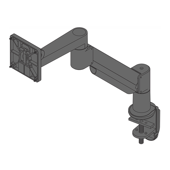
Page 5: Radial Arm Mount With Quick Connect Vesa Plate
2.3 to 7.7 kg (5.0 to 17.0 lbs) display to be mounted on a wall or a tabletop. The Radial Arm Mount allows for easy vertical and horizontal repositioning of the display. Confidential and proprietary information of NCR Corporation. Unauthorized use, reproduction and/or distribution is strictly prohibited. -
Page 6: Installation Procedure
3/8-16 x 1” Flat Socket Cap Screw and 3/8-16 Nylon Stop Nut. b. Install the Small “L” Bracket on the assembly using the 3/8-16 X 1/2” BHSCS. Confidential and proprietary information of NCR Corporation. Unauthorized use, reproduction and/or distribution is strictly prohibited. - Page 7 Rectangular Spacer and 1/2-13 x 3” Socket Set Screw. Then install the Cable Management on the assembly. Thru-Desk a. Drill a 3/8” hole through the tabletop. b. Install the Mount Cup and Mount Cup Rubber Sole as shown. Confidential and proprietary information of NCR Corporation. Unauthorized use, reproduction and/or distribution is strictly prohibited.
- Page 8 Assemble the Mount Cup, Mount Cup Rubber Sole, and Large “L” Bracket using the 3/8-16 x 1” Flat Socket Cap Screw and 3/8-16 Nylon Stop Nut. Confidential and proprietary information of NCR Corporation. Unauthorized use, reproduction and/or distribution is strictly prohibited.
- Page 9 Install the Mount Cup on the Large “L” Bracket using the 3/8-16 x 7/8” Button Socket Cap Screw and 3/8-16 Nylon Stop Nut. Confidential and proprietary information of NCR Corporation. Unauthorized use, reproduction and/or distribution is strictly prohibited.
- Page 10 Install the Mount Cup on the Large “L” Bracket using the 3/8-16 x 1” Flat Socket Cap Screw and 3/8-16 Nylon Stop Nut. 2. Install the Radial Arm on the Mount Cup. Confidential and proprietary information of NCR Corporation. Unauthorized use, reproduction and/or distribution is strictly prohibited.
- Page 11 3. Install the Quick Connect VESA Plate on the display using four (4) M4 x 12 mm Phillips Pan Head Screws. 4. Insert the Tilter into the Quick Connect VESA Plate until it clicks into place. Confidential and proprietary information of NCR Corporation. Unauthorized use, reproduction and/or distribution is strictly prohibited.
- Page 12 5. Install the Tilter on the Arm using the Dog Washer and 10-32 x 3/8” FPhMS with Lock Patch. Confidential and proprietary information of NCR Corporation. Unauthorized use, reproduction and/or distribution is strictly prohibited.
- Page 13 6. Use a 1/8” Allen Wrench to adjust the tilt angle of the display. 7. Check and adjust the Arm for counterbalance. For more information, refer to Counterbalancing the Arm on page 17. Confidential and proprietary information of NCR Corporation. Unauthorized use, reproduction and/or distribution is strictly prohibited.
- Page 14 8. Use a 3/32” Allen Wrench to adjust the horizontal rotation of the arm at the joint as shown. Confidential and proprietary information of NCR Corporation. Unauthorized use, reproduction and/or distribution is strictly prohibited.
- Page 15 9. Route the cable as shown and secure the cable on the arm using the Cable Cap. Note If the Mount Cup is installed over a grommet hole, route the cable down through the hole. Confidential and proprietary information of NCR Corporation. Unauthorized use, reproduction and/or distribution is strictly prohibited.
- Page 16 Confidential and proprietary information of NCR Corporation. Unauthorized use, reproduction and/or distribution is strictly prohibited.
-
Page 17: Counterbalancing The Arm
If the Arm drifts downward, turn the adjustment screw counter-clockwise. Note Depending on the weight of the display, the adjustment screw may have to be turned 15 to 20 times. Confidential and proprietary information of NCR Corporation. Unauthorized use, reproduction and/or distribution is strictly prohibited. - Page 18 2. If the Arm is not staying in position after performing step 1, use a 1/8” Allen Wrench to tighten the adjustment screw in the location shown. Confidential and proprietary information of NCR Corporation. Unauthorized use, reproduction and/or distribution is strictly prohibited.
Need help?
Do you have a question about the VOYIX 1668-K004 and is the answer not in the manual?
Questions and answers