Chapters
Table of Contents

Related Manuals for mundoclima MUCHR-75-H7T


Summary of Contents for mundoclima MUCHR-75-H7T
- Page 1 HIGH PRESSURE DUCT SERIE H7 Service manual MUCHR-75-H7T MUCHR-96-H7T Thank you very much for purchasing our products. CL21532-CL21533 Please read this manual carefully before installing English and using the unit. www.mundoclima.com...
- Page 2 MUCHR-75-H7T MUCHR-96-H7T Service manual Content Part. 1 General information..........2 Part. 2 Indoor Unit.............. 5 Part. 3 Outdoor Unit............13 Part. 4 Installation & Troubleshooting ......25 Part. 5 Controller.............. 53...
- Page 3 MUCHR-75-H7T MUCHR-96-H7T Service manual Part. 1 General information 1. Model Names of Indoor/Outdoor Units ......3 2. External Appearance ............3 3. Nomenclature ..............4...
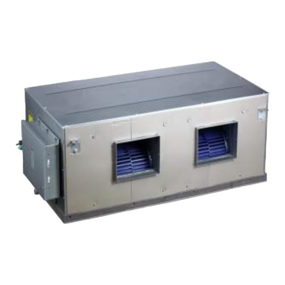
- Page 4 Power supply Hi-static MUCHR-75-H7T-I 220-240V~, 1Ph, MUCHR-75-H7T-E 380-415V~, 3Ph, pressure duct 50Hz 50Hz type Hi-static MUCHR-96-H7T-I 220-240V~, 1Ph, MUCHR-96-H7T-E 380-415V~, 3Ph, pressure duct 50Hz 50Hz type 2. External Appearance 2.1 Indoor units MUCHR-75-H7T-I / MUCHR-96-H7T-I 2.2 Outdoor unit MUCHR-75-H7T-E / MUCHR-96-H7T-E...
- Page 5 MUCHR-75-H7T MUCHR-96-H7T Service manual 3. Nomenclature 3.1 Indoor unit – MU CH R – 96 H I: Indoor unit Serie: Serie 7 H: Heat pump Nominal cooling capacity (96×1,000Btu/h) R: Super DC inverter CH:High static pressure duct type M: Mundoclima 3.2 Outdoor unit...
-
Page 6: Table Of Contents
MUCHR-75-H7T MUCHR-96-H7T Service manual Part. 2 Outdoor Unit 1. Specifications ..............6 2. Dimension (Unit:mm) ............7 3. Refrigerant circuit ............. 8 4. Wiring Diagrams ..............9 5. Electric Characteristics ........... 11 6. Sound Levels ..............12 7. Accessories ..............12... -
Page 7: Specifications
MUCHR-75-H7T MUCHR-96-H7T Service manual 1. Specifications Model MUCHR-96-H7T-E MUCHR-75-H7T-E Power supply V, Ph, 380-415V~, 3Ph, 50Hz 380-415V~, 3Ph, 50Hz Ambient temp in cooling °C -15~48 -15~48 Ambient temp in heating °C -15~24 -15~24 Rated input (Whole units) 11,700 11,100 Rated current (Whole units) -
Page 8: Dimension (Unit:mm)
MUCHR-75-H7T MUCHR-96-H7T Service manual dimension(W×D×H) Packing 1270×1720×565 1270×1720×565 dimension(W×D×H) Net/Gross weight 148/164 147/163 Type R410a R410A Refrigerant Factory charged Throttle type Electronic expansion valve Design pressure (Hi/Lo) 4.4/2.6 Ф9.53 Liquid pipe Refrigerant piping Ф25.4 Gas pipe Note: The nominal cooling capacity is based on the following conditions: Indoor temperature, 27°C DB, 19°C WB; Outdoor temperature, 35°C DB, 24°C WB. -
Page 9: Refrigerant Circuit
MUCHR-75-H7T MUCHR-96-H7T Service manual 3. Refrigerant circuit Electronic Condensor expansion valve High pressure switch High pressure liquid accumulator Oil seperator Evaporator Oil return capilary Compressor Low pressure Low pressure switch liquid accumulator can... -
Page 10: Wiring Diagrams
MUCHR-75-H7T MUCHR-96-H7T Service manual 4. Wiring Diagrams... - Page 11 MUCHR-75-H7T MUCHR-96-H7T Service manual Dial-up function definition S5 function definition S6 function definition Heating priority mode Automatic addressing (set by factory default) 1 2 3 Non-automatic addressing Cooling priority mode (set by factory default) 1 2 3 Initial-start priority mode...
-
Page 12: Electric Characteristics
MUCHR-75-H7T MUCHR-96-H7T Service manual Contents displayed by DSP2 COMM. Fault between IR341 and main chip. COMM. Fault between communication chip and main chip. 3 times of P6 protection in 30 minutes. 3 times of P2 protection in 30 minutes. The number of indoor units decreases. -
Page 13: Sound Levels
MUCHR-75-H7T MUCHR-96-H7T Service manual 6. Sound Levels Front 1.3m Unit Number Model Noise level under three speeds of fan (dB(A)) MUCHR-96-H7T-E MUCHR-75-H7T-E 7. Accessories Accessory name of outdoor unit Qty. Purpose Connection pipe Connecting pipe of system Curved connection pipe... - Page 14 MUCHR-75-H7T MUCHR-96-H7T Service manual Part. 3 Indoor Unit 1.Features ................14 2.Specifications ..............15 3.Dimensions (Unit: mm) ............16 4.Wiring Diagrams ..............17 5.Capacity Table ..............20 6.Static Pressure Curve ............21 7.Electric Characteristics ............. 22 8.Sound Levels ..............22...
-
Page 15: Features
MUCHR-75-H7T MUCHR-96-H7T Service manual 1. Features 1.1 Compact design & convenient installation Convenient installation, hidden in the ceiling, unit installation is not hindered by the location of lighting fixtures or room structure. Air inlet and outlet flanges are standard and easy for duct connection. -
Page 16: Specifications
MUCHR-75-H7T MUCHR-96-H7T Service manual 2. Specifications Model MUCHR-96-H7T-I MUCHR-75-H7T-I 220~240V,1Ph,50Hz Power supply V, Ph, Hz 220~240V,1Ph,50Hz 22,400 Capacity 28,000 7,200 Cooling Input 9,000 3.11 3.11 24,500 Capacity 31,500 6,600 Heating Input 8,500 3.17 3.71 Rated input Rated current Model WZDK750-38GS-W... -
Page 17: Dimensions (Unit: Mm)
MUCHR-75-H7T MUCHR-96-H7T Service manual 3. Dimensions (Unit: mm) Air outlet duct connection screw hole location diagram 1138 Return air duct rivet screw hole location diagram... -
Page 18: Wiring Diagrams
MUCHR-75-H7T MUCHR-96-H7T Service manual 4. Wiring Diagrams... - Page 19 MUCHR-75-H7T MUCHR-96-H7T Service manual Error Code & Indication Mode Conflict Defrost_LED Flash or Show [E0] Communication Error Between Indoor and Outdoor Unit Time_LED Flash or Show [E1] Temp. sensor (T1) Error Run_LED Flash or Show [E2] Temp. sensor (T2) Error Run_LED Flash or Show [E3] Temp.
- Page 20 MUCHR-75-H7T MUCHR-96-H7T Service manual For Setting TERMINAL Fan ON/OFF Interval TYPE 2min 4min 6min Fan Running Factory Setting For Heat Mode Temp. Compensation TYPE 6℃ 2℃ 4℃ 0℃ Factory Setting SW6-1 Digital Tube Display Board LED Indication Display Board TYPE...
-
Page 21: Capacity Table
MUCHR-75-H7T MUCHR-96-H7T Service manual 5. Capacity Table 96 model Cooling mode: Indoor temperature Outdoor temperature (DB °C) DB (°C) WB (°C) 21.0 28.0 35.0 43.0 46.0 52.0 54.0 TC(kW) 28.84 27.44 26.04 24.92 24.08 22.68 21.00 SC(kW) 21.34 21.13 20.83 20.93... - Page 22 MUCHR-75-H7T MUCHR-96-H7T Service manual 75 model Cooling mode: Indoor temperature Outdoor temperature (DB °C) DB (°C) WB (°C) TC(kW) 23.07 21.95 20.83 19.94 19.26 18.14 16.80 SC(kW) 17.07 16.90 16.66 16.74 16.38 15.97 15.12 0.74 0.77 0.80 0.84 0.85 0.88 0.90...
-
Page 23: Static Pressure Curve
MUCHR-75-H7T MUCHR-96-H7T Service manual 6. Static Pressure Curve The corresponding table of electronic control dial code and static pressure range is shown below. For Setting Static Pressure ENC2 Code POWER 0~50 51~80 81~120 121~150 Factory setting Before starting the operation, the installer must set the electronic control dial code based on the actual value of the static pressure of the product .Otherwise, there will be problems. -
Page 24: Electric Characteristics
MUCHR-75-H7T MUCHR-96-H7T Service manual Static curve (ENC2) 3 High air Medium air Low air 3000 3500 4000 4500 5000 5500 air flow (m 7. Electric Characteristics Indoor Unit Power Supply Model Voltage Min. Max. MUCHR-96-H7T-I 220-240V 198V 254V 0.75 MUCHR-75-H7T-I... - Page 25 MUCHR-75-H7T MUCHR-96-H7T Service manual 8. Sound Levels Unit Number Model Noise level under three speeds of fan (dB(A)) MUCHR-96-H7T-I 49~52 MUCHR-75-H7T-I 49~52 9. Accessories Accessory name of indoor unit Qty. Purpose Owner’ manual Installation manual Sealing tape Sealed tube interface...
- Page 26 MUCHR-75-H7T MUCHR-96-H7T Service manual Part. 4 Installation & Troubleshooting 1. Notes ................26 2. Installation of Duct Type Indoor Units ......26 3. Installation of Outdoor Units .......... 30 4. Connection of Refrigerant Pipe ........33 5. Electric Connection ............34 6.
-
Page 27: Notes
MUCHR-75-H7T MUCHR-96-H7T Service manual 1. Notes CAUTION: Install the unit where enough space of installation and maintenance is available. Install the unit where the air inlet and outlet are not baffled and the least affected by external air. - Page 28 MUCHR-75-H7T MUCHR-96-H7T Service manual Pipe side 2.2 Install Φ10 pendant bolts or ground bolts Use Φ10 or bigger screws. The screw material is high-quality carbon steel (whose surface is zinc plated or undergoes other rustproof treatment) or stainless steel.
- Page 29 MUCHR-75-H7T MUCHR-96-H7T Service manual The treatment of the ceiling varies between buildings. For detailed measures, consult with the fitting-out staff. Fix the pendant bolts firmly and reliably in light of the specific situation. Installation of the pendant bolt in different environments.
- Page 30 MUCHR-75-H7T MUCHR-96-H7T Service manual 2.4 Design and connection of duct The duct design must comply with the national heating air conditioner pipeline design specifications The duct accessories and materials must be produced by professional manufacturers. In order to prevent air flow shorting, do not keep the air inlet pipe near the air outlet pipe.
-
Page 31: Installation Of Outdoor Units
MUCHR-75-H7T MUCHR-96-H7T Service manual Caution: Rubbish is easy to accumulate at drain stream trap. Make sure to install a plug or other things which is easy to clean. 2. Test draining Open the clapboard of indoor unit, pour the water in to see whether it drain smoothly and whether there is water leakage. - Page 32 MUCHR-75-H7T MUCHR-96-H7T Service manual Parallel connect the front with rear sides 3.2 Moving and installation Since the gravity center of the unit is not at its physical center, so please be careful when lifting it with a sling. Never hold the inlet of the outdoor unit to prevent it from deforming.
- Page 33 MUCHR-75-H7T MUCHR-96-H7T Service manual 3.4 Install the connecting pipe of outdoor Check whether the height drop between the indoor unit and outdoor unit, the length of refrigerant pipe, and the number of the bends meet the following requirements: The indoor and outdoor connecting pipe interface and power line outlet Various piping and patterns can be selected, such as out from the front, the back, the side, and undersurface, etc.
-
Page 34: Connection Of Refrigerant Pipe
MUCHR-75-H7T MUCHR-96-H7T Service manual 4. Connection of Refrigerant Pipe 4.1 Size of outdoor unit pipes and piping methods Model Gas side Liquid side MUCHR-96-H7T-E Φ25.4mm Φ9.5mm MUCHR-75-H7T-E MUCHR-96-H7T-I Φ25.4mm Φ9.5mm MUCHR-75-H7T-I... -
Page 35: Electric Connection
MUCHR-75-H7T MUCHR-96-H7T Service manual 4.2 Allowed length of refrigerant pipe and height difference Allowed value Max. actual length of pipe (L) Outdoor (upper) Height difference between indoor Max. height difference unit and out door unit (H) Outdoor (lower) 4.3 Refrigerant Replenishment Quantity ... - Page 36 MUCHR-75-H7T MUCHR-96-H7T Service manual national rule. The appliance shall be installed in accordance with national wiring regulations. 5.2 Specifications of power supply MUCHR-96-H7T-I MUCHR-96-H7T-E Model MUCHR-75-H7T-I MUCHR-75-H7T-E Power 220-240V~50Hz 380-415V 3N~50Hz Switch capacity of the main power supply 16/16...
-
Page 37: Duct Design Scheme
MUCHR-75-H7T MUCHR-96-H7T Service manual 6. Duct Design Scheme Examples of construction and ventilation pipeline design scheme (Flowering hidden series.) Construction and ventilation pipeline design scheme 7. Trial Run Please conduct in accordance with the nameplate of Trial Run Tenor on the electric control box. -
Page 38: Trouble Shooting
MUCHR-75-H7T MUCHR-96-H7T Service manual Do not perform compulsory operation in any way, because it is very dangerous if the protection device is not active. Perform trial run only after all installations are finished. Confirm the following issues before trial operation: ... - Page 39 MUCHR-75-H7T MUCHR-96-H7T Service manual Outdoor input current protection Compressor discharge temperature protection Display H6, if three times in 100 minutes Pipe temperature protection Inverter module protection Display H4, if three times in 60 minutes. Typhoon protection Evaporator high temperature protection...
- Page 40 MUCHR-75-H7T MUCHR-96-H7T Service manual E2: Indoor & outdoor unit communication error E2: Indoor units and outdoor unit communication error Communication wires P, Q, E are short circuit or Reconnect the communication wires. disconnected. (Measure the resistance among P, Q and E, the normal resistance is 120Ω.)
- Page 41 MUCHR-75-H7T MUCHR-96-H7T Service manual E4: Ambient temp. T4/pipe temp. T3 sensor error E7: Discharge temp. sensor T7 error E4: T3/T4/T7 sensor error T3/T4/T7 port on main control board is loose. Fasten the T3/T4/T7 port. T3/T4/T7 sensor is short circuit or disabled. (Using a multimeter to measure resistance, if the Replace the sensor..
- Page 42 MUCHR-75-H7T MUCHR-96-H7T Service manual Notes: 1. How to check whether the compressor is short circuit ①: The normal resistance value of inverter compressor among U V W is 0.7~1.5Ω, and infinity to earth. If the resistance value is out of the range, the compressor is abnormal.
- Page 43 MUCHR-75-H7T MUCHR-96-H7T Service manual H0: Communication error between main control chip and module chip; H1: Communication error between main control chip and communication chip H0/H1 Power supply for main PCB, transformer 1 and Provide normal power supply. transformer 2 terminals are abnormal.
- Page 44 MUCHR-75-H7T MUCHR-96-H7T Service manual H8: High pressure sensor error When the discharge pressure is lower than 0.3MPa, the system will display H8 error, the ODU in standby. When the discharge pressure is back to normal, H8 disappears and normal operation resumes.
- Page 45 MUCHR-75-H7T MUCHR-96-H7T Service manual P0: Top temperature protection of compressor P4: Discharge temperature protection P0: Top temperature protection of compressor. P4: Discharge temperature protection. Connect again or replace the Check whether the sensor is well or connected well.
- Page 46 MUCHR-75-H7T MUCHR-96-H7T Service manual P2: Low pressure protection P2/H5: Low pressure protection System is lack of refrigerant. (Refrigerant recharging is not according to the Add refrigerant or check up the requirement, or there has refrigerant leakage of the system.
- Page 47 MUCHR-75-H7T MUCHR-96-H7T Service manual P3: Over-current protection of compressor P3: When the current of inverter compressor is over12A, the system will display P3 protection, the ODU in standby. When the current goes back to normal range, P3 disappears and normal operation resumes.
- Page 48 MUCHR-75-H7T MUCHR-96-H7T Service manual P5: Pipe temperature protection P5: Pipe temperature protection T3 port on main control board is loose. Fasten T3 port. T3 sensor is short circuit or disabled. Replace the sensor. Make sure the ratio of connectable IDU is The indoor load is too large.
- Page 49 MUCHR-75-H7T MUCHR-96-H7T Service manual P6: Inverter module protection P6, L0~L9 error codes can’t display on digital tube automatically, these error codes will display on digital tube only through SW3 button (pressure SW3 ten times, every one second for a time) If the system display three times P6 protection in 60 minutes, the system will stop and display H4 error code.
- Page 50 MUCHR-75-H7T MUCHR-96-H7T Service manual Step 2: Module check 1) DC voltage between terminal P and terminal N should be 1.41 times of the local power supply voltage. 2) DC voltage between terminal 1 and 2 should be 510V~580V. 3) Disconnect the terminal 3, 4, and 5 from inverter compressor. Measure the risistance between any two terminals among terminal 1, 2, 3, 4, 5.
- Page 51 MUCHR-75-H7T MUCHR-96-H7T Service manual Step 2: Check whether the wires of rectifier circuit are loose or not. If wires are loosen, fasten the wires. If wires are OK, replace the main PCB. 3-Phase bridge rectifier Filter board 3) L2 troubleshooting Step 1: Check the DC voltage between 1 and 2 terminal, the normal value should be 510V~580V, if the voltage is higher than 580V, go to step 2.
- Page 52 MUCHR-75-H7T MUCHR-96-H7T Service manual If the value is not in the range, that means the power supply for electrolytic capacitors has problem, you should check the power supply, whether the voltage is too high and whether the voltage is stable.
- Page 53 MUCHR-75-H7T MUCHR-96-H7T Service manual P9: DC Fan module protection P9/H9: Fan module protection The fan module is too hot for bad heat Make sure the fan module working dissipation or high ambient temperature. in the normal temperature range. Some power wires or signal wires of fan Well connect the power wires and module are loose.
- Page 54 MUCHR-75-H7T MUCHR-96-H7T Service manual Part. 5 Controller 1. Wired Controller: KJR-29B1/BK-E (Standard) ....54 2. Touch Key Centralized Controller: CCM30 ..... 62...
- Page 55 MUCHR-75-H7T MUCHR-96-H7T Service manual 1. Wired Controller: KJR-29B1/BK-E (Standard) KJR-29B1/BK-E 1.1 Wired controller specifications KJR-29B/BK-E Model Power Supply Voltage 5.0V DC Ambient Temperature Range -5°C~43°C Ambient Humidity Range RH40%~RH90% Performance Features 1. Operating mode: cool, heat, dry, fan and auto.
- Page 56 MUCHR-75-H7T MUCHR-96-H7T Service manual 1.2 Wired controller outlook 1.3 Operation instructions 1) Remote signal receiving function: the wired controller can be a remote signal receiving device, it is possible to use the wireless remote controller to control the air conditioner through the wired controller when the system have been powered on.
- Page 57 MUCHR-75-H7T MUCHR-96-H7T Service manual 4) Fan speed setting Under COOL, HEAT and FAN modes, press the fan speed button can adjust the fan speed setting. After each fan speed button press will circle as follow: Auto Note: Under AUTO and DRY modes the fan speed is not adjustable and the default fan speed is auto.
- Page 58 MUCHR-75-H7T MUCHR-96-H7T Service manual 8) Quiet operation Under COOL, HEAT, FAN modes, press the button to set into the quiet operation, it is used to reduce the running noise through setting the fan speed to low. Note: Under AUTO, DRY mode, the fan speed is auto and the button does not work.
- Page 59 MUCHR-75-H7T MUCHR-96-H7T Service manual Do not install the controller in a place vulnerable to leakage of flammable gases. Once flammable gases are leaked and left around the wired controller, fire may occur. The wiring should adapt to the wired controller current. Otherwise, electric leakage or heating may occur and result in fire.
- Page 60 MUCHR-75-H7T MUCHR-96-H7T Service manual Wiring principle sketch: Wiring figure: Connect two terminals of embedded 4-core shielding wire with the switching wires of wired controller and signal receiving board. Make sure the sequence of 4 terminals (A, B, C and D) should correspond to the wire...
- Page 61 MUCHR-75-H7T MUCHR-96-H7T Service manual If the embedded 4-core shielding wire cannot go through the wired controller, it can use signal switching for connection; make sure the wires are reliable and firm. The tightening torque range of screw is: 0.8~1.2N·m (8~12kgf·cm).
- Page 62 MUCHR-75-H7T MUCHR-96-H7T Service manual Adjust the length of two plastic screw bars in the accessory to be standard length from the electrical box screw bar to the wall. Make sure when install the screw bar to the electric box screw bar, make it as flat as the wall.
- Page 63 MUCHR-75-H7T MUCHR-96-H7T Service manual Wired controller’s front cover installation: After adjusting the front cover and then buckle the front cover. Avoid clamping the communication switching wire during installation. Correct install the back cover and firmly buckle the front cover and back over, otherwise will make the front cover drop off.
- Page 64 MUCHR-75-H7T MUCHR-96-H7T Service manual The parameter setting table First Second code Function code Cooling-only/Heat pump Coolin Heat pump (Default) selection g only Indoor unit communication Yes (Default) None address setting Power-off memory Yes (Default) None Cancel the reminding 1250 2500...
- Page 65 MUCHR-75-H7T MUCHR-96-H7T Service manual 2.1 General functions and description Query key Any time when you press the key, the selected operation mode is to query the operational state of the air conditioner. By default, the first in-service air conditioner will be queried.
- Page 66 MUCHR-75-H7T MUCHR-96-H7T Service manual the key repeatedly to shift between a single setting and global setting. Single Global Mode key Under the setting operation mode, press this key to set the operation. Cooling Heating Fan only Fan key Under the setting operation mode, press this key to set the fan of the indoor unit to run in the automatic, high, medium or low level of air.
- Page 67 MUCHR-75-H7T MUCHR-96-H7T Service manual Upward key (11) In the main page, press this key can enter the query mode. By default, it is the first in-service air conditioner. In any other time, press this key will select the previous corresponding position air conditioner.
- Page 68 MUCHR-75-H7T MUCHR-96-H7T Service manual Any time when the reset key is pressed, the centralized controller will reset. The result is the same as the result of restoring power-on after power failure. (17) Lock key Any time when this key is pressed, the selected air conditioner can be locked or unlocked.
- Page 69 MUCHR-75-H7T MUCHR-96-H7T Service manual 2.2 LCD display 2.3 Other operations ※ Various locking functions 1. Centralized controller locking The centralized controller locking state will be recorded when powered off. It won't dismiss when re-power on...
- Page 70 MUCHR-75-H7T MUCHR-96-H7T Service manual until receiving the unlocking order. 1) Effect ① When the centralized controller is under locking state, it cannot change the air conditioner's operating state through the centralized controller (such as ON/OFF the unit, setting mode, change the setting temperature, change the fan speed, unlock the exiting locking state etc.), but it can do the query operation, until unlocking...
- Page 71 MUCHR-75-H7T MUCHR-96-H7T Service manual The buzzer long buzz for 2 seconds: all display segments of the LCD are luminous for 2 seconds and then goes off; 1 second later, the system enters normal display state. The centralized controller is in the main page display state and displays the first page, and searches the in-service air conditioners in the network.
- Page 72 MUCHR-75-H7T MUCHR-96-H7T Service manual following situations: 1) If there are one or more air conditioners is under ON state (include timing process of timing ON and OFF), " " key only short press effective. Only sends the shutdown order to the air conditioner which under the ON state, and if the unit is under the OFF state, the controller will not send OFF order to it.
- Page 73 MUCHR-75-H7T MUCHR-96-H7T Service manual function from table 2.2. Press " " and " " keys can select function, and then press " " key to enter parameter selection. ② After entering parameter selection, the function selection icon (as show in a part of the Fig. A) will be lighted on;...
- Page 74 MUCHR-75-H7T MUCHR-96-H7T Service manual 2.4 Fault and Protection codes Fault code content Other fault. Water level detection malfunction. Reserved. Cleaning malfunction. Inverter module protection. Current of compressor is too large (4 Times). Communication malfunction between main board and display board.
- Page 75 MUCHR-75-H7T MUCHR-96-H7T Service manual 2.5 General display data entries 1) General display data is displayed in all display pages. • Under the interconnected control of the computer or gateway, the data is displayed in graphic ( Otherwise, no data is displayed.
- Page 76 MUCHR-75-H7T MUCHR-96-H7T Service manual 3) LCD display description Description of the main page The LCD displays the main page, 60 air conditioners are in service, of which 28 are powered on and 32 off. In the matrix, the bid dots from (16+, 00) to (32+, 15) are luminous, and the small dots are not luminous. It indicates the 32 air conditioners with the addresses from 16 to 47 are powered off.
- Page 77 MUCHR-75-H7T MUCHR-96-H7T Service manual with the addresses 01 and 15 are in service. The centralized controller communicates with the computer normally. Fault page display description Query the air conditioner with the address of 08 in the query page. The air conditioner with the address of 08 is faulty, and fault code is 08. The big black dot below (00+, 08) blinks.
- Page 78 MUCHR-75-H7T MUCHR-96-H7T Service manual CCM30 BKE/A CCM30 BKE/B...
- Page 79 MUCHR-75-H7T MUCHR-96-H7T Service manual ※ Installation diagram ※ Terminal instruction...
- Page 80 ASK FOR MORE INFORMATION Phone: (+34) 93 446 27 81 eMail: info@mundoclima.com TECHNICAL ASSISTANCE Phone: (+34) 93 652 53 57 www.mundoclima.com...
Need help?
Do you have a question about the MUCHR-75-H7T and is the answer not in the manual?
Questions and answers