
Related Manuals for mundoclima H6M Series


Summary of Contents for mundoclima H6M Series
- Page 1 MULTI INVERTER SERIE H6M Installation and owner's manual Thank you very much for purchasing our products. CL20440 to CL20457 Please read this manual carefully before installing English and using the unit. www.mundoclima.com...
-
Page 2: Table Of Contents
CONTENT INSTALLATION MANUAL .................... 3 Safety precautions ......................4 Indoor unit installation ....................5 Outdoor unit installation ....................6 Refrigerant pipe connection ..................8 Electrical installation .....................10 Drain joint installation ....................12 Start up and performance testing .................12 Function of automatic wiring/piping correction .............13 OWNERS MANUAL .................... -
Page 3: Installation Manual
INSTALLATION MANUAL Before using your air conditioner, please read this manual carefully and keep it for future reference.. INVERTER SPLIT-TYPE ROOM AIR CONDITIONER The design and specifications are subject to change without prior notice for product improvement. Consult with the sales agency or manufacturer for details. -
Page 4: Safety Precautions
SAFETY PRECAUTIONS 1. Safety precautions Read the follow SAFETY PRECAUTIONS carefully before installation. Electrical work must be installed by a licensed electrician. Be sure to use the correct rating of the power plug and main circuit for the model to be installed. Incorrect installation due to ignoring of the instruction will cause harm or damage. -
Page 5: Indoor Unit Installation
INDOOR UNIT INSTALLATION 2. Indoor unit installation Fit the installation plate 1) Fit the installation plate horizontally on structural parts of the wall with spaces arround the installation plate. 2) If the wall is made of brick, concrete or like, drill five or eight 5mm diameter holes in the wall. -
Page 6: Outdoor Unit Installation
INDOOR AND OUTDOOR UNIT INSTALLATION Connective pipe and drainage installation 1. Run the drain hose sloping downward. Do not put the end of Do not install the drain hose as Do not block water flow by a rise. drain hose into water. illustrated in Fig.7. - Page 7 OUTDOOR UNIT INSTALLATION Dimensions Unit: mm Model MUEX-14-H6.2 MUEX-18-H6.2 MUEX-21-H6.3 MUEX-27-H6.3 MUEX-28-H6.4 1034 MUEX-36-H6.4 1034 MUEX-42-H6.5 1034 Space for installation and maintenance...
-
Page 8: Refrigerant Pipe Connection
REFRIGERANT PIPE CONNECTION 4. Refrigerant pipe connection Before installing, make sure that the height difference, the length of refrigerant pipe and number of bends between indoor and outdoor units, meet the following specifications. Outdoor unit UNIT 2 x 1 (H6.2) 3 x 1 (H6.3) 4 x 1 (H6.4) 5 x 1 (H6.5) - Page 9 REFRIGERANT PIPE CONNECTION D: Flaring work Handle Firmly hold copper pipe in a die in the dimension shown in the table below. Yoke A(mm) Cone Outer diam. (mm) Max. Min. Copper pipe 6.35 Clamp handle 9.53 Red arrow mark 12.7 12.7 Fig.57 Tightening connection...
-
Page 10: Electrical Installation
ELECTRICAL INSTALLATION 5. Electrical installation Safety standards - The supply voltage must be within a range of 90% to 110% of nominal value. - The thermal circuit breaker and breaker should be 1.5 times the nominal consumption. - All installation and wiring must comply with local and national average and the installation should be performed by qualified personnel. - Page 11 ELECTRICAL INSTALLATION 2 x 1 L(A) N(A) S(A) L(B) N(B) S(B) MUEX-14-H6.2 MUEX-18-H6.2 POWER W 1(L) 2(N) S W 1(L) 2(N) S TO A TO B 3 x 1 L(B)N(B) S(B) L(C)N(C) S(C) L(A)N(A) S(A) MUEX-21-H6.3 MUEX-27-H6.3 POWER W 1(L) 2(N) S W 1(L) 2(N) S W 1(L) 2(N) S TO B...
-
Page 12: Drain Joint Installation
DRAIN JOINT and START UP AND PERFORMANCE TESTING 6 . Drain joint installation Fit the seal into the drain joint, then insert the drain joint into the base pan hole of outdoor unit, 。 rotate 90 to securely assemble them. Connecting the drain joint with an extension drain Base pan hole of Drain joint... -
Page 13: Function Of Automatic Wiring/Piping Correction
AUTOMATIC WIRING/PIPING CORRECTION 8. Function of automatic wiring/piping correction Automatic Wiring/Piping Correction Function: More recent models now feature automatic correction of wiring/piping errors. Press the "check switch" on the outdoor unit PCB board for 5 seconds until the LED displays "CE”, indicating that this function is working, Approximately 5-10 minutes after the switch is pressed, the "CE"... -
Page 14: Owners Manual
OWNER´S MANUAL Before using your air conditioner, please read this manual carefully and keep it for future reference.. INVERTER SPLIT-TYPE ROOM AIR CONDITIONER The design and specifications are subject to change without prior notice for product improvement. Consult with the sales agency or manufacturer for details. -
Page 15: Safety Precautions
SAFETY PRECAUTIONS 1. Safety precautions Read the follow SAFETY PRECAUTIONS carefully before installation. Electrical work must be installed by a licensed electrician. Be sure to use the correct rating of the power plug and main circuit for the model to be installed. Incorrect installation due to ignoring of the instruction will cause harm or damage. -
Page 16: Description And Operating Instructions
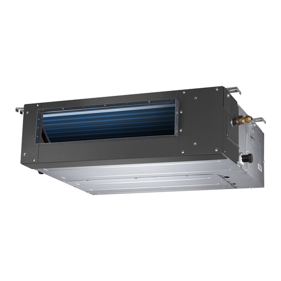
DESCRIPTION AND OPERATING INSTRUCTIONS 2. Description and operating instructions Parts a) Wall mounted MUPR-H6M Indoor unit Unit C 1. Front panel 2. Top air intake 3. Air filter(Inside) 4. Air outlet 5. Horizontal air flow louver 6. Vertical air flow louver(Internal) Unit B 7. - Page 17 DESCRIPTION AND OPERATING INSTRUCTIONS c) Cassette MUCSR-H6M b) Duct MUCR-H6M Unit E Unit E Unit D Unit D Unit C Unit C Unit B Unit B Unit A Unit A Indoor unit Indoor unit 1. Drain pump (drain water from indoor unit) 1.
- Page 18 DESCRIPTION AND OPERATING INSTRUCTIONS Operating temperature Mode Cooling operation Heating operation Drying operation Temperature Room temperature >17 C(62 F) 0 C~50 C Outdoor temperature (32 F~122 F) NOTE: 1. Optimum performance will be achieved within these operating temperatures.If air conditioner is used outside of the above conditions, certain safety protection features might come into operation and cause the unit to function abnormally.
- Page 19 DESCRIPTION AND OPERATING INSTRUCTIONS For some models, the vertical louver can only be adjusted manually. Move the deflector rod manually to adjust the air flow in the direction you prefer. IMPORTANT:Do not put your fingers into the panel of blower and suction side. The high-speed fan inside may cause danger.
-
Page 20: Care And Maintenance
CARE AND MAINTENANCE 3. Care and maintenance Cleaning the grille, case and remote controller Turn the system off before cleaning. To clean, wipe with a soft, dry cloth. Do not use bleach or abrasives. NOTE: Supply power must be disconnectd before cleaning the indoor unit. - Page 21 CARE AND MAINTENANCE Manitenance If you plan to idle the unit for a long time, perform the following: 1 . Cl ean th e i nd oor unit and ai r filt er. 2. Select FAN only mode, let the indoor fan run for a while to dry the inside of the unit. 3.
-
Page 22: Troubleshooting
TROUBLESHOOTING 4. Troubleshooting Stop the air conditioner immediately if one of the following faults occur. Disconnect the power and contact the nearest customer service center. If the E( 0,1..) or P( 0, 1 ..) code appears on the LED(LCD)window, disconnect the power and contact the service people. - Page 23 TROUBLESHOOTING Indoor Unit Error code Operation Lamp Malfunction Error Code Timer Lamp (flashes) Indoor EEPROM malfunction Communication malfunction between indoor and outdoor units Indoor fan speed has been out of control Open or short circuit of T1 temperature sensor Open or short circuit of T2 temperature sensor Water level alarm Overcurrent protection (For some units) Open or short circuit of T4 temperature sensor...
-
Page 24: Disposal
DISPOSAL 5. Disposal When using this air conditioner in the European countries, the follow information must be followed: Disposal: Do not dispose this product as unsorted municipal waste. Collection of such waste separately for special treatment is necessary. It is prohibited to dispose of this appliance in domestic household waste. For disposal, there are several possibilities: A) The municipality has established collection systems, where electronic waste can be disposed of at least free of charge to the user. -
Page 25: Remote Controller
REMOTE CONTROLLER Please read this Owner's Manual carefully before operation. Save this manual in a safe place for future reference. - Page 26 "Owner's manual" shall prevail. IMPORTANT NOTE: This remote controller is able to set different parameters, it has a function selection. For more information, please contact with Mundoclima after sales service or with your commercial sales.
- Page 27 REMOTE CONTROLLER OPERATION OF BUTTONS ON/OFF Button This button turns the air conditioner ON and OFF. MODE Button Press this button to modify the air conditioner mode in a sequence of following: HEAT AUTO COOL FAN Button Used to select the fan speed in four steps: AUTO HIGH NOTE: You can not switch the fan speed in...
- Page 28 REMOTE CONTROLLER SWING Button Used to stop or start horizontal louver auto swing feature. DIRECT Button Used to change the louver movement and set the desired up/down air flow direction. The louver changes 6 in angle for each press. NOTE: When the louver swing or move to a position which would affect the cooling or heating effect of the air conditioner, it would automatically change the...
- Page 29 REMOTE CONTROLLER INDICATORS ON LCD Mode display AUTO COOL HEAT Displayed when data transmitted. Displayed when remote controller is ON. Battery display(low battery detection) Not available for this unit Information are displayed when Displayed when TIMER ON time is set. the remote controller is powered Displayed when TIMER OFF time is set.
- Page 30 REMOTE CONTROLLER HOW TO USE THE BUTTONS Auto operation Ensure the unit is plugged in and power is available. The OPERATION indicator on the display panel of the indoor unit starts flashing. 1. Press the MODE button to select Auto. 2.
- Page 31 REMOTE CONTROLLER Dehumidifying operation Ensure the unit is plugged in and power is available. The OPERATION indicator on the display panel of the indoor unit starts flashing. 1. Press the MODE button to select DRY mode. 2. Press the UP/DOWN buttons to set the desired temperature.
- Page 32 REMOTE CONTROLLER To set the Auto-off time. 1. Press the TIMER OFF button. The remote controller shows TIMER OFF, the last Auto-off setting time and the signal "H" will be shown on the LCD display area. Now it is ready to reset the Auto-off time to stop the operation.
- Page 33 REMOTE CONTROLLER (Auto-off Operation) TIMER OFF The TIMER OFF feature is useful when you want the unit to turn off automatically after you go to bed. The air conditioner will stop automatically at the set time. Example: To stop the air conditioner in 10 hours. 1.
- Page 34 REMOTE CONTROLLER HANDLING THE REMOTE CONTROLLER Location of the remote controller Use the remote controller within a distance of 8 meters from the appliance, pointing it towards the receiver. Reception is confirmed by a beep. CAUTIONS The air conditioner will not operate if curtains, doors or other materials block the signals from the remote controller to the indoor unit.
- Page 35 REMOTE CONTROLLER b) Wired remote controller I. Safety precautions The following contents are stated on the product and the operation manual, including usage, precautions against personal harm and property loss, and the methods of using the product correctly and safely. After fully understanding the following contents (identifiers and icons), read the text body and observe the following rules.
- Page 36 REMOTE CONTROLLER 2. Installation accessory 2.1 Select the installation location Don’t install at the place where cover with heavy oil, vapor or sulfureted gas, otherwise, this product would be deformed that would lead to system malfunction. 2.2 Preparation before installation 1.
- Page 37 REMOTE CONTROLLER 2. Remove the upper part of wire controller Insert a slot screwdriver into the slots in the lower part of the wire controller (2 places), and remove the upper part of the wire controller. (Fig.3-2) NOTICE The PCB is mounted in the upper part of the wire Slots controller.
- Page 38 REMOTE CONTROLLER 5. Wire the indoor unit 4 methods 1 from the rear; 2 from the bottom; 3 from the top; 4 from the top center. HA HB HA HB HA HB HA HB 1 indoor unit 2 notch the part for the wiring to pass through with nippers, etc. Connect the terminals on the remote controller (HA ,HB), and the terminals of the indoor unit (HA ,HB).
- Page 39 REMOTE CONTROLLER 4. Specification DC 5V/DC 12V Input voltage Ambient temperature -5~43℃(23~110℉) RH40%~RH90% Ambient humidity Wiring specifications Wiring type Total length Size Shielded vinyl cord or cable 0.75-1.25mm <50m Copy/ Swing Timer Day off/Del Confirm Back/Turbo Follow me...
- Page 40 REMOTE CONTROLLER 6. Name on the LCD of the wire controler 1 Operation mode indication 8 Turbo function indication 2 Fan speed indication 9 C° / F° indication 3 Left-right swing indication 10 Temperature display 4 Up-down swing indication 11 Lock indication 5 Faceplate function indication 12 Room temperature indication 6 Main unit and secondary unit indication...
- Page 41 REMOTE CONTROLLER 8. Preparatory operation Set the current day and time Timer Press the TIMER button for 3 seconds or more. The timer display will flash. Press the button “ + ” or “ - ” to set the date. The selected date will flash.
- Page 42 REMOTE CONTROLLER Fan speed setting Press the FAN SPEED button to set the fan speed. (This button is unavailable when in the mode of Auto or Dry) Fan speed (Lock) Room temperature sensor selection Copy/ Follow me Indoor Unit Press the Follow me button to select whether the room temperature is detected at the indoor unit or the wire controller.
- Page 43 REMOTE CONTROLLER Faceplate function (on some models) 1.When the unit is off, Press the Mode(A/B) button long to activate the faceplate function. The mark will flash. Mode The F2 mark appears when the faceplate is adjusted. 2. Push the Mode(A/B) button to select Unit A or Unit B, the wire controller select in a sequence that goes from (this step do not need to perform if the wire controller is connected with one unit only): 3.
- Page 44 REMOTE CONTROLLER 10. Timer functions On timer Use this timer function to start air conditioner operation.The timer operates and air conditioner operation starts after the time has passed. Off timer Use this timer function to stop air conditioner operation.The timer operates and air conditioner operation stops after the time has passed.
- Page 45 REMOTE CONTROLLER To set the On and Off TIMER Timer Press the TIMER button to select the Confirm Press the CONFIRM button and the Clock display is flashing. Confirm Press the button “ + ” or “ - ” to set the time of On timer, and then press the CONFIRM button to confirm the setting.
- Page 46 REMOTE CONTROLLER ex.Tuesday time scale 1 Up to 4 timer settings can be saved for each day of the week.It is conventent if the WEEKLY TIMER is set according to the user’s life style. Off timer setting of timer setting 1 Confirm Press the button “...
- Page 47 REMOTE CONTROLLER To set the DAY OFF (for a holiday) During the weekly timer, press the Confirm button. Confirm Press the button “ + ” or “ - ” to select the day in this week . Press the Day off button to set the DAY OFF. Day off/Del mark is hidden ex.The DAY OFF is set for Wednesday...
- Page 48 REMOTE CONTROLLER Copy/ Press the Copy button,the letter “CY” will be Follow me shown on the LCD. Press the button “ + ” or “ - ” to select the day to copy to. Press the Copy button to confirm . Copy/ Follow me mark flashes quickly...
- Page 49 REMOTE CONTROLLER 11. Fault alarm handing If the system does not properly operate except the above mentioned cases or the above mentioned malfunctions is evident, investigate the system according to the following procedures. D ISPLAY MALFU N C T ION & PROT EC T ION D EFIN E D IGITAL TUBE Error of communication between wire controler and indoor unit...
- Page 50 ASK FOR MORE INFORMATION Phone: (+34) 93 446 27 81 eMail: info@mundoclima.com TECHNICAL ASSISTANCE Phone: (+34) 93 652 53 57 www.mundoclima.com...
Need help?
Do you have a question about the H6M Series and is the answer not in the manual?
Questions and answers