Advertisement
Quick Links
Unpacking
Open the carton and unpack the items. Your package should include:
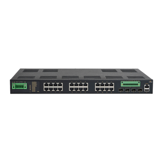
1 IG5 rackmount managed Ethernet switch
2 Mounting brackets
8 M4 rack screws
1 RJ45 console cable
A quick installation guide and the following model-specific accessories:
Model Series
Items
Q'ty
1
RCS, RCSL
Power cable
2
RCR, RCRL
Power protection cover
1
M3 power cover screws
2
FWR, FWRL, FWS,FWSL
Spacer bolts
2
What Else You Need
Appropriate cables for data ports. To prevent switch damage from electrical
surges, it is recommended to use STP (Shielded twisted pair) cabling.
Personal computer or laptop
Appropriate SFP modules for SFP ports
Select a Location
Installation: Rack mount. Use the enclosed brackets and screws to mount
the switch in an open or enclosed 19" rack.
Select a power source within 6 feet (1.8 meters).
Choose a dry area with ambient temperature as follows:
Ambient Temperature
Model Series
-40 ºC to 75ºC (-40 ºF to 167ºF)
FTR, FWR, FWS
-40 ºC to 65ºC (-40 ºF to 149ºF)
RCR, RCS
-10 ºC to 60ºC (14 ºF to 140ºF)
FTRL, FWRL, RCRL, FWSL, RCSL
Keep away from heat sources, sunlight, warm air exhausts, hot-air vents,
and heaters.
Be sure there is adequate airflow.
Connect to the Data Ports
Depending on the model, your switch can have the following ports:
0, 8, 16, or 24 10/100/1000 Mbps TX ports
0, 8,16, or 24 100/1000Base-SFP ports
4 SFP+ slots, supporting 10Gbps or 1Gbps
Use Category 5e or higher UTP/STP cable for TX ports. For SFP and SFP+ ports,
ensure that the same type of transceiver is used at both ends of the link and that
the correct type of fiber cable is used.
Connect Power
Power Input Interfaces
Corresponding voltage
Model Series
Redundant Single Input
24VDC to 48VDC
FTR , FTRL
■
FWR, FWRL
■
100-240VAC / 100-250VDC
FWS, FWSL
■
RCR, RCRL
100-240VAC
RCS, RCSL
InfraGreEn IG5 | Rack Series Managed Ethernet Switch
FTR / FTRL models: Connect the switch to a suitable power supply using 12
to 24 AWG wire. It is suggested to use two power sources to power the IG5.
Dual Power
Models
Supplied by a Listed Power Adapter or DC power source, rated ±24 VDC or
±48 VDC, minimum 1 A, SELV/ES1 and evaluated in accordance with UL/IEC
60950-1 and/or UL/IEC 62368-1. If you need further assistance with
purchasing the power source, contact EtherWAN Systems Inc. for further
information.
FWR/FWS/FWRL/FWSL models: Remove the two screws on the terminal
block and replace with the supplied spacer bolts. After connecting the
power wires to the terminal block, affix the power protection cover over the
terminal bock and secure with the supplied M3 screws.
RCR/RCS/RCRL/RCSL models: Connect the supplied AC power cords to the
AC power receptacles at the rear of the switch.
Relay Output Alarm
The switch provides two relay output contacts. Both Relay 1 and Relay 2 signal
actions from one of the digital inputs. The relay outputs can be connected to an
alarm signaling device. The Current is 0.5A@48VDC at Normal Open or Normal
Closed.
Normal state: 3 & 2 closed, 2 & 1 open
Alarm state: 3 & 2 open, 2 & 1 closed
Power-Up Sequence
When the switch is powered up:
All Link/ACT LEDs blink momentarily.
The Power 1, 2 LEDs light up and stay lit.
LEDs for every port connected to a device will flash, as the switch conducts a
brief Power On Self-Test (POST).
Front Panel LEDs
LED Panel Layout
Inlet
Type
Terminal
Power 1 & 2 = Power input detection status
Block
Green LED ON = Network connection
Terminal
FLASHING = Port sending or receiving data
Block
■
RED = Link down or power down
AC Inlet
■
Copyright 2024 EtherWAN Systems, Inc. All Rights Reserved 4/16/2024
Installation Guide
Console Configuration
Connect to the switch console by connecting the RJ45 console cable to the
console port of the switch and to the serial port of the computer running a SSH
(Secure Shell protocol) application by V2 or above (such as HyperTerminal or
Putty) in default.
Configuration settings of the terminal-emulation program (Need to be enabled in
advance): Baud rate: 115,200bps, Data bits: 8, Parity: none, Stop bit: 1, Flow
control: none.
The default login name is "root," no password.
Web Configuration
Log in to the switch by launching a "HTTPS" web browser and entering
192.168.1.10 in the address bar as default settings. Then enter the default login
ID: root (no password) and click "Login."
USB Port
The switch is equipped with one USB port (Type A connector) for configuration
file and syslog backup. The USB port can be used to save the configuration and
Syslog to a (FAT32) USB storage device.
Plug the device into the USB port and use the "Save Configuration" command in
the web interface, or "copy running-config startupconfig" in the CLI. Use the
"Export Logs to USB" command in the web interface, or "export logs" in the CLI.
Digital IO-Setting
Connecting the Digital Inputs
The pin definitions for the digital input module are shown below. Each digital
input consists of two contacts on the 5-pin connector located on the top of the
switch. The inputs can be wired as either dry or wet contacts.
Dry Contacts:
[DI1-/GND] [DI2-/GND]
Logic level 1: Close to GND
Logic level 0: Open
Wet Contacts:
[DI1+/DI1-] [DI2+/DI2-]
Logic level 1 (High): 13~30 Volts
Logic level 0 (Low): 0~3 Volts
Configuring Digital Input Alarms Using the Web Interface
Located under the Diagnostics group, the Digital IO-Setting page allows for quick
configuration and enabling of digital input and environmental alarms.
W70G-IG5Q3
Page 1
Advertisement

Related Manuals for EtherWAN Rack Series


Summary of Contents for EtherWAN Rack Series
- Page 1 60950-1 and/or UL/IEC 62368-1. If you need further assistance with Log in to the switch by launching a “HTTPS” web browser and entering purchasing the power source, contact EtherWAN Systems Inc. for further Power protection cover 192.168.1.10 in the address bar as default settings. Then enter the default login information.
- Page 2 InfraGreEn IG5 | Rack Series Managed Ethernet Switch Installation Guide FWR/FWRL series terminal block: FWS/FWSL series terminal block: Read these instructions carefully before connecting the system to the power Safety Information source. Keep these instructions for later reference. The power cord must be connected to a properly earth grounded outlet.
Need help?
Do you have a question about the Rack Series and is the answer not in the manual?
Questions and answers