
Related Manuals for ITT Engineered Valves C67


Summary of Contents for ITT Engineered Valves C67
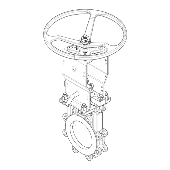
- Page 1 Installation, Operation, and Maintenance Manual C67 Bi-Directional Knife Gate Valve...
-
Page 3: Table Of Contents
Table of Contents Table of Contents 1 Introduction and Safety ............................ 2 1.1 Safety message levels ..........................2 1.2 User health and safety ..........................2 2 Transport and Storage ............................4 2.1 Handling and unpacking guidelines......................4 2.2 Lift the valve .............................. 4 2.3 Storage, disposal, and return requirements .................... -
Page 4: Introduction And Safety
1.2 User health and safety General precautions This product is designed and manufactured using good workmanship and materials, and meets all appli- cable industry standards. This product should be used only as recommended by an ITT engineer.. WARNING: • Misapplication of the valve can result in injury or property damage. Select valves and valve components of the proper materials and make sure that they are consistent with your specific performance requirements. - Page 5 • Ensure that the contents of the operating instructions have been fully understood by the personnel. Instruction and training can be carried out by either ITT or the reseller of the valve by order of the operat- ing company. Non-compliance risks Failure to comply with all safety precautions can result in the following conditions: •...
-
Page 6: Transport And Storage
2 Transport and Storage 2 Transport and Storage 2.1 Handling and unpacking guidelines CAUTION: Always observe the applicable standards and regulations regarding the prevention of accidents when handling the product. Handling guidelines Follow these guidelines when handling the product to prevent damage: •... -
Page 7: Storage, Disposal, And Return Requirements
2.3 Storage, disposal, and return requirements If the valve is handwheel-operated, then turn the handwheel so that one spoke is aligned perpen- dicular to the flow direction (or parallel with the gate). Prepare the valve for lifting: If your valve is... Then... Handwheel-op- Loop the lifting strap under the yoke. - Page 8 Store in accordance with the short-term action items. months • Store in accordance with ITT's Long Term Storage Procedure. Contact ITT to obtain this procedure. Disposal Dispose of this product and associated components in compliance with federal, state, and local regula- tions.
-
Page 9: Product Description
Contact ITT to request a maintenance manual for another manufacturer's actuator, limit switch, position- er, controller, or other accessory. -
Page 10: Universal Yoke
3.2 Universal Yoke 3.2 Universal Yoke Design overview The valve features weld-free 304 stainless yoke plates which simplify top works conversions. The yoke design also allows for simpler mounting of valve control accessories and gate shrouds. Additionally, the yoke comes standard with lockout pin holes for locking both the open and closed positions. Features Same yoke across various operators allows for easy conversion from one operator to another. -
Page 11: Installation
4 Installation 4 Installation 4.1 Install the chest liner (if provided) Remove the entire valve (including topworks) from the pipeline. Secure the valve in the vertical position to a fixture, workbench, or table that is anchored to the floor. Do not block valve port when anchoring valve. An overhead hoist is helpful especially on larger size valves. -
Page 12: Preinstallation
Air cylinders, when provided, are sized for a specified input pressure. Excessive pressure could result in serious personal injury or may cause damage to the valve and cylinder. Air regulators and air filters are available from ITT or your authorized ITT distributor. NOTICE: •... -
Page 13: Preparation Before Installation
Bolt the valve to the mating flange using the proper size fasteners. See the Recommended fasteners table in this section. ITT recommends you use studs to ensure the full thread engagement of tapped holes. Lubricate stainless steel fasteners to prevent galling. -
Page 14: Check After Installation
4.5 Check after installation 4.5 Check after installation Operate the actuator to have the valve full open or closed for several times smoothly to make sure it is in good condition. Check the tightness at the connection face between the pipe and valve. Valve shall not be used to replace the blind flange for the piping pressure testing. -
Page 15: Maintenance
External valve parts Excessive wear or corrosion • Replace the affected parts • Contact ITT to obtain replace- ment parts or for specific in- structions 5.3 Lubrication requirements Lubrication schedule The stem and stem nut of the knife gate valve are lubricated at the factory before shipment. -
Page 16: Adjust The Packing
5.4 Adjust the packing 5.4 Adjust the packing The packing may require some adjusting after the line pressure is up to normal. Stroke the valve a few times. Tighten the packing gland bolts just enough to stop the leakage. Over tightening the packing may cause undue pressure against the gate making the valve difficult to operate and causing packing wear. -
Page 17: Packing Dimensions
5.6 Replace the seal NOTICE: Position the packing gland so it is centered on the gate, but not touching the gate. Improper installation may result in premature packing failure. Replace the packing gland nuts and tighten them so that the packing gland sets the packing. NOTICE: Do not tighten the packing gland nuts completely. - Page 18 5.6 Replace the seal Open the valve fully. Remove the yoke, topworks, and packing gland from the valve: Remove the yoke fasteners and gate clamp fasteners. Lift off the yoke and topworks. Remove gland fasteners and packing gland. Lift out the gate, clean it, and smooth out any marred or rough surfaces with a scotch-brite pad. The gate should be free of grooves and scratches.
- Page 19 5.6 Replace the seal Valve size (in.) Valve size Length in body Length in body From centerline From centerline to (DN) (in.) (cm) to top of chest top of chest (cm) (in.) 110.9 281.69 55.4 140.72 135.6 344.42 67.8 172.21 Replace the seal: Saturate the body seal groove and both ends of the seal with liquid soap or any good water- soluble lubricant that will not harm the seal or process.
- Page 20 5.6 Replace the seal Length in body mark Starting inside the port at the 9 o’clock center line position, place the other end of the seal into the seal groove with a rubber mallet. Indentations are cast inside the port for guidance. Force the seal into the groove.
- Page 21 5.6 Replace the seal Pull the seal up the groove inside the chest, applying constant pressure until the last mark on the seal is in line with the top of the chest. Length in body mark Work the seal into the bottom of the body with pliers and a rubber mallet. Centerline mark The centerline point marked on the seal should be at the center of the body.
-
Page 22: Set The Stroke
5.7 Set the stroke 14. Cut each end of the seal off to the required extended length. Extended length Valve size (in.) Valve size (DN) Extended length (in.) Extended length (cm) 1.250 3.175 1.250 3.175 1.250 3.175 1.812 4.602 1.875 4.763 1.875 4.763... - Page 23 5.7 Set the stroke Is the valve handwheel-actuated? • If no: Proceed to step 2. • If yes: No adjustment is necessary. The stroke is set at the factory. Is the valve bevel gear-actuated? • If no: Proceed to step 3. •...
- Page 24 5.7 Set the stroke Screw the gate clamp (3) fully into the cylinder rod. Reattach the gate to the gate clamp and close the valve. Measure the distance from the tip of the gate to the top of the seal at the bottom of the port. Tip of the gate to the top of the seal Adjustment distance iii.
-
Page 25: Troubleshooting
6 Troubleshooting 6 Troubleshooting 6.1 Knife gate valve operation troubleshooting Symptom Cause Remedy Jams during operation Crystallization of medium on seat and Clean debris on seat and gate gate Damage on gate and seat Replace gate and seat Medium built inside of body Clear the medium inside body Internal leakage exceeds standard Abrasive wear on seat... -
Page 26: Parts Listings And Cross-Sectional
7 Parts Listings and Cross-Sectional 7 Parts Listings and Cross-Sectional 7.1 Drawing and parts list Exploded view C67 Bi-Directional Knife Gate Valve Installation, Operation, and Maintenance Manual... - Page 27 7.1 Drawing and parts list Parts list Item Description Material Handwheel Ductile Iron Yoke Hub 304 Stainless Steel Yoke Assembly 304 Stainless Steel Stem Assembly Bolts Stainless Steel Packing Gland 304 Stainless Steel Packing PTFE/Graphite, Acrylic/PTFE Packing Support Bars Brass, PTFE FDA or GR TFE Yoke Nuts Stainless Steel Lock Pin...
- Page 28 Visit our website for the latest version of this document and more information: http://www.engvalves.com ITT Engineered Valves 1110 Bankhead Avenue Amory, MS 38821 Form IOM.C67.en-US.2024-05 ©2024 ITT Industries Ltd. The original instruction is in English. All non-English instructions are translations of the original instruction.
Need help?
Do you have a question about the Engineered Valves C67 and is the answer not in the manual?
Questions and answers