Table of Contents
Advertisement
Quick Links
1
重点
校对项
认证图标
A
1.物料编码
单位表述
产地表述
2.版面尺寸
变更要求
3.材质标注
B
4.颜色标注
5.客户型号
6.产品名称
C
7.产品参数
8.电压功率
9.单位符号
10.认证标志
D
11.回型标志
12.ROHS标志
E
13.警语警语
及字高
14.控制面板
及功能
15.目录及
F
页码
16.商标LOGO
1、印刷颜色:钉装,单色印刷;
2、说明书幅面大小为: 210*290MM;
G
3、1:1图纸在第二页;
*应研发要求更新P27接线图-彭娟-20231212
标记 处 数 更改文件号
H
制 图
设 计
校 对
会 签
1
2
标准元素核对表(此表仅用于印刷品制作过程核对标准内容,非印刷内容)
大于5mm
大于5mm
大于5mm 大于5mm 大于7mm
直流电:
交流电:
V~
频率:
Hz
功率:
W
MADE IN CHINA
Made in China
Made in P.R.C
图纸变更需要核实变更内容点以及涉及的物料和MO单,尤其关注92的在途MO单
技术要求(版本号: A , 2018-01)
签 字 日 期
彭娟
审 核
卢灿飞
-----
标准化
古广君
-----
审 定
古广君
日 期
20231019
-----
2
3
0000000
0 0 0 0 0 0
ETL有C或US或C+US
UL只有C+US或无
容量:
mL/L
电流:
A
压强:
Pa/kPa/MPa 长度:mm/cm/m 时间:s/min/h重量:kg
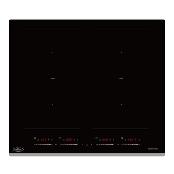
多头电磁炉
使用说明书
K
1
3
4
5
01
PET
GS图标无高度要求,印刷可见即可
PET材质 合成纸材质
Belling-MC-6F74A0H556 BIHF60BK
材料:100G双胶纸
1:1
广东美的生活电器制造有限公司
1
4
5
6
05
A
PP
B
C
D
E
F
G
PN:16166000A31289
H
6
Advertisement
Table of Contents

Related Manuals for Belling BIHF60BK


Summary of Contents for Belling BIHF60BK
- Page 1 及字高 14.控制面板 及功能 15.目录及 页码 技术要求(版本号: A , 2018-01) 16.商标LOGO 1、印刷颜色:钉装,单色印刷; 2、说明书幅面大小为: 210*290MM; 3、1:1图纸在第二页; PN:16166000A31289 *应研发要求更新P27接线图-彭娟-20231212 多头电磁炉 Belling-MC-6F74A0H556 BIHF60BK 使用说明书 材料:100G双胶纸 标记 处 数 更改文件号 签 字 日 期 制 图 彭娟 审 核 卢灿飞 ----- 设 计 标准化 古广君...
- Page 2 Belling BIHF60BK...
-
Page 8: Electrical Shock Hazard
Foreword Safety Warnings Your safety is important to us. Please read this information before using your cooktop. Installation Electrical Shock Hazard work or maintenance on it. Cut Hazard Important safety instructions appliance as it could reduce your installation costs. instructions for installation. person. -
Page 9: Health Hazard
Operation and maintenance Electrical Shock Hazard Health Hazard this appliance to make sure that their implants will not be affected by the electromagnetic field. Hot Surface Hazard Induction glass until the surface is cool. Cut Hazard children. Important safety instructions affected by its electromagnetic field. - Page 10 instructor should be satisfied that they can use the appliance without danger to as this can scratch the glass. Congratulations oon the purchase of your new induction Hob. please read the installation section.
-
Page 11: Product Introduction
PRODUCT INTRODUCTION Top View Max. 2200/ Max. 2200/ 3300 W zone 3300 W zone Free induction zone. Free induction zone. 3300/3700 W 3300/3700 W Max. 2200/ Max. 2200/ 3300 W zone 3300 W zone Glass plate Control panel Control Panel Pause control Boost control Timer control... -
Page 12: Working Theory
Working Theory Induction cooking is a safe, advanced, efficient, and economical cooking technology. It works by electromagnetic vibrations generating heat directly in the pan, rather than indirectly through heating the glass surface. The glass becomes hot only because the pan eventually warms it up. Iron pot Magnetic circuit Ceramic glass plate... -
Page 13: Pan Dimension
• Cookware bases with aluminium content. • These reduce the ferromagnetic area,whitch means that less power is emitted to the Cooware. This cookware may not be sufficiently detected or may not be detected at all,And therefore does not heat sufficienty. •... -
Page 14: How To Use
HOW TO USE Start Cooking Touch the ON/OFF control. After power on, the buzzer beeps once, heating zone selection controls show “ - ” , indicating that the induction hob has entered the state of standby mode.mode. Place a suitable pan on the cooking zone that you wish to use. •... -
Page 15: Using The Boost Function
Beware of hot surfaces H/h will show which cooking zone is hot to touch. It will disappear when the surface has cooled down to a safe temperature. It can also be used as an energy saving function if you want to heat further pans, use the hotplate that is still hot. -
Page 16: Locking The Controls
Examples of good pot placement and bad pot placement. Locking the Controls • You can lock the controls to prevent unintended use (for example children accidentally turning the cooking zones on). • When the controls are locked, all the controls except the ON/OFF control are disabled. To lock the controls Touch the lock control The digital will show “Lo”... - Page 17 Time decrease button, long press and short press are effective. At the same time, press the timing plus or minus button for 1s to cancel the timing. Pause When the cooking zones are running, touch the “ II ” control, all the displays will show “...
-
Page 18: Default Working Times
Confirmation Disconfirmation Blinking with sound Blinking with sound 1. No pot is displayed after 6 seconds Press the flashing bunner's boost 2. 10 seconds later, turn off the key to confirm the transfer blinking and prompt sound Operate the RF slide. cancel the transfer RF bunner is heated at LR bunner level and heat in the set gear Default Working Times... -
Page 19: Cooking Tips
QUICK START GUIDE Take care when frying as the oil and fat heat up very quickly, particularly if you’re using PowerBoost. At extremely high temperatures oil and fat will ignite spontaneously and this presents a serious fire risk. Cooking Tips •... -
Page 20: Heat Settings
HEAT SETTINGS The settings below are guidelines only. The exact setting will depend on several factors, including your cookware and the amount you are cooking. Experiment with the induction hob to find the settings that best suit you. Heat setting Suitability •... -
Page 21: Cleaning Your Appliance
CLEANING YOUR APPLIANCE Do’s Note: Always switch off your appliance and allow it to cool down before you clean any part of it. Note: Please take extra care when cleaning over the symbols on the control panel, as this can lead to them fading. -
Page 22: Troubleshooting
TROUBLESHOOTING Operation of your appliance can lead to errors and malfunctions. The following tables contain possi- ble causes and notes for resolving an error message or malfunction. It is recommended to read the tables carefully below in order to save your time and money that may cost for calling to the service center. -
Page 23: Failure Display And Inspection
Failure Display and Inspection The induction hob is equipped with a self diagnostic function. With this test the technician is able to check the function of several components without disassembling or dismounting the hob from the working surface. (1) Troubleshooting Problem Possible causes What to do! - Page 24 (2) Specific Failure & Solution Failure Problem Solution A Solution B Check to see if plug is secured tightly in outlet and No power supplied. that outlet is working. The LED does not come on when unit is The accessorial power board plugged in.
-
Page 25: Product Installation
PRODUCT INSTALLATION Selection of Installation Equipment Cut out the work surface according to the sizes shown in the drawing. For the purpose of installation and use, a minimum of 5 cm space shall be preserved around the hole. Be sure the thickness of the work surface is at least 30mm. Please select heat-resistant and insulated work surface material (Wood and similar fibrous or hygroscopic material shall not be used as work surface material unless impregnated) to avoid the electrical shock and larger deformation caused by the heat radiation from the hotplate. -
Page 26: Before Locating The Fixing Brackets
WARNING: Ensuring Adequate Ventilation Make sure the induction cooker hob is well ventilated and that air inlet and outlet are not blocked. In order to avoid accidental touch with the overheating bottom of the hob, or getting unexpectable electric shock during working, it is necessary to put a wooden insert, fixed by screws, at a minimum distance of 15mm from the bottom of the hob. - Page 27 Adjusting the Bracket Positio Fix the hob on the work surface by insert 4 brackets on the bottom of hob(see picture) before installation. Adjust the bracket position to suit for different table top thickness. bracket Under any circumstances, the brackets cannot touch with the inner surfaces of the worktop after installation (see picture).
-
Page 28: Connecting The Hob To The Mains Power Supply
Connecting the Hob to the Mains Power Supply This hob must be connected to the mains power supply only by a suitably qualified person. Before connecting the hob to the mains power supply, check that: 1. The domestic wiring system is suitable for the power drawn by the hob. 2. -
Page 29: Disposal And Recycling
DISPOSAL AND RECYCLING Important instructions for environment Compliance with the WEEE Directive and Disposing of the Waster Product: This product complies with EU WEEE Directive (2012/19/EU). This product bears a classification symbolfor waster electrical and electronic equipment (WEEE). This symbol indicates that this product shall not be disposed with other household wastes at the end of its service life. - Page 30 Your Belling Appliance is guaranteed against breakdown for an initial period of 12 months from date of purchase (for guarantee conditions please refer to your instruction booklet) Your standard one year guarantee is extended for an additional 12 months when you register the product within 28 days of purchase with Glen Dimplex Ireland.
-
Page 31: Technical Data
TECHNICAL DATA Hob Details BIHF60BK Cooking Hob Cooking Zones 4 Zones Supply Voltage 220-240V~ 50Hz or 60Hz Installed Electric Power 7400W Product Size L×W×H(mm) 590X520X53 Building-in Dimensions A×B (mm) 560X480 Weight and Dimensions are approximate. Because we continually strive to improve our products we may change specifications and designs without prior notice.
Need help?
Do you have a question about the BIHF60BK and is the answer not in the manual?
Questions and answers