Table of Contents
Advertisement
Quick Links
Operating instruction – Spindle lifting system SN/SO 13xx with SCT iSMPS
It is essential to read this operating instruction thoroughly before commissioning the system.
The manual must be kept in close proximity to the system for future reference.
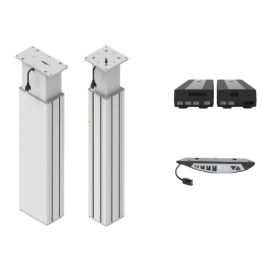
Spindle lifting column of Type SN or SO
Control box SCT iSMPS
Hand switch Memory
Errors and technical changes reserved.
Ergoswiss AG does not assume any liability for operating errors or
using the products outside of the intended purpose use.
At the time of delivery Ergoswiss AG will replace or repair defect
products within accordance with the warranty provisions.
In addition, Ergoswiss assumes no other liability.
For your questions and special custom demand Ergoswiss AG will
be at your disposal.
Document no.: B-00511
Edition 2024 04
Spindle lifting system SN/SO 13xx with SCT iSMPS
1
Operating instruction EN
Copyright by Ergoswiss AG
Operating instruction
2
3
Ergoswiss AG
Nöllenstrasse 15
CH-9443 Widnau
Tel.: +41 (0) 71 727 06 70
Fax: +41 (0) 71 727 06 79
info@ergoswiss.com
www.ergoswiss.com
Page 1 of 29
Advertisement
Table of Contents
Troubleshooting

Related Manuals for Ergoswiss SN 13 Series


Summary of Contents for Ergoswiss SN 13 Series
- Page 1 CH-9443 Widnau Tel.: +41 (0) 71 727 06 70 At the time of delivery Ergoswiss AG will replace or repair defect Fax: +41 (0) 71 727 06 79 products within accordance with the warranty provisions.
- Page 2 The declaration of incorporation is only valid for the Ergoswiss lifting system and not for the overall system created by the further-user.
-
Page 3: Table Of Contents
10 Error codes and trouble shooting ..................27 10.1 Error codes on the display ..................... 27 10.2 Trouble shooting ........................28 11 Declaration of Incorporation ....................29 Document no.: B-00511 Operating instruction EN Page 3 of 29 Edition 2024 04 Copyright by Ergoswiss AG... -
Page 4: Safety Requirements
NOTE Indicates general information, useful user tips and work recommendations, which have no im- pact on the health and safety of staff. Document no.: B-00511 Operating instruction EN Page 4 of 29 Edition 2024 04 Copyright by Ergoswiss AG... -
Page 5: System Description
2 System description 2.1 General The basic functionality of a spindle lifting system SN/SO by Ergoswiss AG is the lifting and lowering of work surfaces, machine parts, profile systems, etc. An operative spindle lifting System SN/SO consists of a minimum of following components: →... -
Page 6: Target Group And Prior Knowledge
(e.g. through constructive measures or through instructions in the operating instructions and/or through safety indication on the system). In the event of improper use, the liability of Ergoswiss AG and the general operating permit for the lifting system will expire. -
Page 7: Performance Characteristics
2/40 stat. = during standstill; dyn. = during stroke movement Duty Cycle 2/40; operating max. 2 min, pause 40 min Document no.: B-00511 Operating instruction EN Page 7 of 29 Edition 2024 04 Copyright by Ergoswiss AG... -
Page 8: Control Box Sct2 Ismps And Sct4 Ismps
2.4.3 Hand switch Up/Down and Memory RJ-12 plug 6 Pin Electrical connection Cable length 2 m (79”) Protection class (DIN EN 60529) IP 30 Document no.: B-00511 Operating instruction EN Page 8 of 29 Edition 2024 04 Copyright by Ergoswiss AG... -
Page 9: System Data
High pulse / impact forces due to the discontinuation of loads are not allowed. (e.g. discontinuation of loads in feed with crane or forklift) Document no.: B-00511 Operating instruction EN Page 9 of 29 Edition 2024 04 Copyright by Ergoswiss AG... -
Page 10: Mounting Instructions
Mounting on T-slot (Cross bar) Mounting at bottom Outer profile with T-slots Foot plate with thread (Screw size M8) (0.3”) Screw-in depth max. 8 mm Document no.: B-00511 Operating instruction EN Page 10 of 29 Edition 2024 04 Copyright by Ergoswiss AG... - Page 11 4x thread for screw size M8 (0.3”) Screw-in depth max. 8 mm 1x thread for screw size M10 (drawing in mm) Document no.: B-00511 Operating instruction EN Page 11 of 29 Edition 2024 04 Copyright by Ergoswiss AG...
-
Page 12: Mounting Instructions Control Box
3 extension cables. They have a length of 1’000 mm each. (39’’) 124.00290: Extension cable Hand switch SCT 1m Document no.: B-00511 Operating instruction EN Page 12 of 29 Edition 2024 04 Copyright by Ergoswiss AG... - Page 13 → Are the plugs of the motor cable connected to the correct sockets (1 to 4)? → Is the entire lifting system assembled according to the assembly instructions? 8. Connect power cable to the mains. Document no.: B-00511 Operating instruction EN Page 13 of 29 Edition 2024 04 Copyright by Ergoswiss AG...
-
Page 14: Mounting Instructions Hand Switch
The control panel must overhang below the work sur- face! 2. Fasten the hand switch using the mounting screws. Be careful not to drill through the table top! Document no.: B-00511 Operating instruction EN Page 14 of 29 Edition 2024 04 Copyright by Ergoswiss AG... -
Page 15: Initial Operation
The maximum continuous operating time is 2 minutes. Afterwards a pause of at least 40 minutes needs to be observed before the system can be operated again. Document no.: B-00511 Operating instruction EN Page 15 of 29 Edition 2024 04 Copyright by Ergoswiss AG... -
Page 16: Operation With Hand Switch Type Memory
The memory position is now stored under the pressed button. To approach a stored memory position: Keep one of the buttons pressed until the desired working height is reached. Document no.: B-00511 Operating instruction EN Page 16 of 29 Edition 2024 04 Copyright by Ergoswiss AG... -
Page 17: Limit The Stroke Length (Container-Stop/Shelf-Stop)
NOTE To delete a set Container-stop position, a new one has to be done with the same procedure. Document no.: B-00511 Operating instruction EN Page 17 of 29 Edition 2024 04 Copyright by Ergoswiss AG... -
Page 18: Setting The Shown Height On The Display "S 06
The unit of measurement on the display has now been changed from centimeters (cm) to inches (inch) or from inches to centimeters (2.54 cm = 1 inch). Document no.: B-00511 Operating instruction EN Page 18 of 29 Edition 2024 04 Copyright by Ergoswiss AG... -
Page 19: Deactivating / Activating The Tilt Sensor "S 08
4. If the tilt sensor is activated, the message «E dd» appears. For the new initialization of the tilt sensor, a «Reference drive» must now be performed. Document no.: B-00511 Operating instruction EN Page 19 of 29 Edition 2024 04 Copyright by Ergoswiss AG... -
Page 20: Locking The Movement (Child Protection)
The control gives an acoustic signal to confirm the deactivation. The system is not locked anymore and can be operated normally. Document no.: B-00511 Operating instruction EN Page 20 of 29 Edition 2024 04 Copyright by Ergoswiss AG... -
Page 21: Reference Drive - Referencing The End Positions
4. Let go of the buttons After reaching the block position, the lower and the upper position will be stored automatically. The Reference drive is completed. Document no.: B-00511 Operating instruction EN Page 21 of 29 Edition 2024 04 Copyright by Ergoswiss AG... -
Page 22: Restore To Factory Settings - Factory Reset "S 00
6. Press the button to leave the menu mode. The display shows «E dC». 7. Do an initial operation according to chapter 4. Document no.: B-00511 Operating instruction EN Page 22 of 29 Edition 2024 04 Copyright by Ergoswiss AG... -
Page 23: Operation With Hand Switch Type Up-Down
4. Let go of the buttons After reaching the block position, the lower and the upper position will be stored automatically. The Reference drive is completed. Document no.: B-00511 Operating instruction EN Page 23 of 29 Edition 2024 04 Copyright by Ergoswiss AG... -
Page 24: Synchronize 2 Control Boxes
→ Is the entire lifting system assembled according to the assembly instructions? 6. Connect power cable to the mains. 7. Perform the initial operation according to chapter 4. Document no.: B-00511 Operating instruction EN Page 24 of 29 Edition 2024 04 Copyright by Ergoswiss AG... -
Page 25: Safety Strip - Squeezing Protection
Spindle lifting system SN/SO 13xx with SCT iSMPS 8 Safety strip – Squeezing protection ATTENTION With lifting systems of Ergoswiss AG it is important to make sure that no objects or people are trapped during the lifting movement. Danger of squeezing during lifting movement! Attach the safety strip to an assumed squeeze zone. -
Page 26: Maintenance And Disposal
The lifting system is not covered by the Electrical and Electronic Equipment Act (WEEE Directive 2012/19/EU). Lifting systems from Ergoswiss AG are intended for installation in an overall system (e.g. assembly table) and classified under the category of incomplete machines in accordance with the Machinery Regulation (EU) 2023/1230. -
Page 27: Error Codes And Trouble Shooting
Motor turns faster than expected by E CC Contact customer support the control box Document no.: B-00511 Operating instruction EN Page 27 of 29 Edition 2024 04 Copyright by Ergoswiss AG... -
Page 28: Trouble Shooting
Drive only move to one direction Hand switch defective Replace the hand switch Drive only moves downwards System overload Remove weight from the system Document no.: B-00511 Operating instruction EN Page 28 of 29 Edition 2024 04 Copyright by Ergoswiss AG... -
Page 29: Declaration Of Incorporation
Operating instruction Spindle lifting system SN/SO 13xx with SCT iSMPS 11 Declaration of Incorporation Document no.: B-00511 Operating instruction EN Page 29 of 29 Edition 2024 04 Copyright by Ergoswiss AG...
Need help?
Do you have a question about the SN 13 Series and is the answer not in the manual?
Questions and answers