
Related Manuals for Raytools XC3000S Series


Summary of Contents for Raytools XC3000S Series
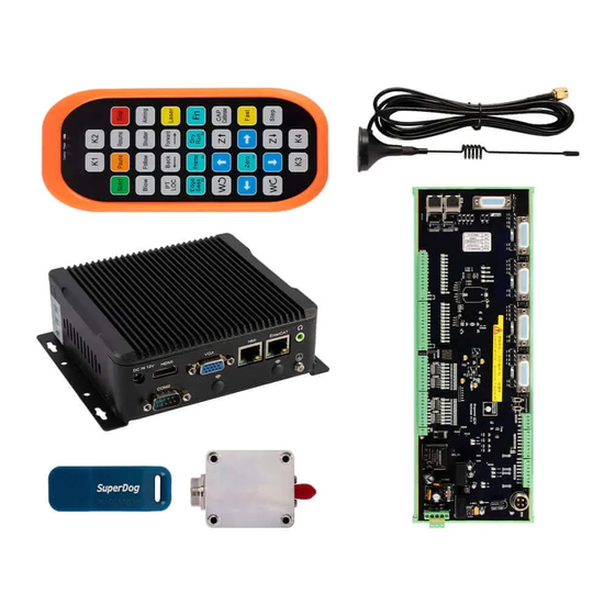
- Page 1 XC3000S Series Laser Cutting System Commissioning Manual XCS3000S Laser Cutting System Commissioning Manual B Laser Delivery C IOT A CNC System...
- Page 2 XC3000S Series Laser Cutting System Commissioning Manual Document History Edit date Version Topic, revision, action taken 2023/5/26 V1.2 First edition Thank you for choosing our product! This manual describes the installation and commissioning of laser cutting head in details so that you can use this product quickly.
- Page 3 XC3000S Series Laser Cutting System Commissioning Manual Disclaimer ▪ We reserve the right to change the design in order to improve the quality or expand the application or comply to manufacturing workmanship. ▪ We will not bear any responsibility for losses and accidents caused by wrong operation or improper handling of our products.
- Page 4 XC3000S Series Laser Cutting System Commissioning Manual Safety Instructions Prevent Electric Shock ▪ Parts of the laser head such as nozzle, sensor, sensor interface and attached fasteners may not be fully protected by the ground wire due to function fault. These parts may have low voltage. When installing electrical equipment, please pay attention to taking anti electric shock measures for relevant personnel.
-
Page 5: Table Of Contents
XC3000S Series Laser Cutting System Commissioning Manual Catalog 1 Product Overview ..............................7 1.2 System connection schematic ........................8 Technical parameters ......................... 10 2 Wiring instructions ............................11 2. 1 EPC-1020 interface description ......................11 2. 1 .1 EPC-1020 interface description ....................12 EPC-2000 interface description ......................12 2.2.1 EPC2000 Interface Layout ....................... - Page 6 XC3000S Series Laser Cutting System Commissioning Manual 6.2.1 Control BM109 Cutting head abnormal treatment ..............87 6.2.2 BM111 Yaskawa Focusing Driver ....................87 Normal Questions ..........................87 6.3.1 Host cannot enter the system ....................88 6.3.2 Enter the system sheet showing that the slave is not connected or not in OP status ..88 7 Appendix ................................93...
-
Page 7: Product Overview
1 Product Overview The manual includes the summarized instruction of installation, setting, use and operation of professional RAYTOOLS XC3000S Series laser cutting software. Main functions are introduced here as there are too many modules to describe. XC3000S Series laser cutting software is a professional CNC software of RAYTOOLS, adapted to industrial laser production application. -
Page 8: System Connection Schematic
XC3000S Series Laser Cutting System Commissioning Manual 1.2 System connection schematic Bus type servo connection method... - Page 9 XC3000S Series Laser Cutting System Commissioning Manual Pulse type servo connection method...
-
Page 10: Technical Parameters
XC3000S Series Laser Cutting System Commissioning Manual Technical parameters EtherCAT Support standard EtherCAT for flexibleaccess to the system topology 5-way universal interface of axis, which can be adapted to different Control Method types of servo drives and provide high-precision position feedback,... -
Page 11: Wiring Instructions
XC3000S Series Laser Cutting System Commissioning Manual 2 Wiring instructions 2. 1 EPC-1020 interface description EPC-1020 (optional) is our new HMI PC, with good performance in graphics processing and response speed. EPC-1020 Network Card 2× Gigabit NIC 4 x USB3.0, 1 built-in USB2.0 onboard... -
Page 12: Epc-1020 Interface Description
EPC-2000 real-time EtherCAT master PC is the core component of motion control system of the machine, developed by Raytools technology with motion control algorithm and professional control logic designed for laser use. It also supports a variety of modes like online upgrade or real-time upgrade, with features... - Page 13 XC3000S Series Laser Cutting System Commissioning Manual including good stability, anti-interference ability, high-performance computing mode, and easy to upgrade and operate. EPC-2000 2×Gigabit NIC Network Card 4×USB2.0,2个USB3.0 1×2.5HD,1×MSATA Storage Device -20℃~60℃ Ambient temperature 5%~95% Ambient humidity Support both HDMI / VGA interface...
-
Page 14: Epc2000 Interface Layout
XC3000S Series Laser Cutting System Commissioning Manual 2.2.1 EPC2000 Interface Layout Startup button HMI(LAN2)master control module communication interface EtherCAT(LAN1)connection interface DC power input 9-36VDC EtherCAT ( LAN1 ) port is defined as EtherCAT connection interface to be connected with the servo motor and EDS board. -
Page 15: Eds3000 Interface Description
XC3000S Series Laser Cutting System Commissioning Manual 2.3 EDS3000 Interface Description EDS3000 is an EtherCAT-based slave interface board with a rich set of IO, motion control and laser follow interfaces and resources, especially for signal acquisition and motion control applications in the laser industry. -
Page 16: Eds3000 Interface Description
XC3000S Series Laser Cutting System Commissioning Manual 2.3.1 EDS3000 Interface Description The board has a boundary dimension of 122mm*348mm and can be assembled on a module rack for mounting on the DIN C45 rail. On the upper left there are 4 DB15 ports for external servo drives. From left to right, they are Y-axis, X-axis, Y1-axis and Z-axis. -
Page 17: Power Supply Interface Description
XC3000S Series Laser Cutting System Commissioning Manual 2.3.2 Power supply interface description EDS3000 board power interface needs to be externally connected to the DC24V switching power supply, where the 24V, 0V and PE input terminals are connected to the output interface... -
Page 18: Digital Input Interface
XC3000S Series Laser Cutting System Commissioning Manual 2.3.3 Digital input interface When COM1 is connected to 24V, the input signal is active low; when COM1 is connected to 0V, the input signal is active high. Take NPN and PNP sensors as an example: When using the NPN type limit, the COM1 port is connected to 24V. -
Page 19: Digital Output Interface
XC3000S Series Laser Cutting System Commissioning Manual When COM1 is connected to 24V, the input signal is active low; when COM1 is connected to 0V, the input signal is active high. Take contact switch as an example. Active low-evel connection... -
Page 20: Analog Input Interface
XC3000S Series Laser Cutting System Commissioning Manual All DO1~DO16 output 24V high level, with the maximum output current of 0.5A. If it’s connected to a high- power load, please connect an external relay and connect a current- continuing diode (MIC 10A6) in parallel with the oxygen and nitrogen solenoid valve. -
Page 21: Pwm Interface
XC3000S Series Laser Cutting System Commissioning Manual 2.3.7 PWM Interface There are 2 PWM pulse width modulation signals, which can be used to control the average power of the fiber laser. The PWM signal supports 24V or 5V (manually adjusting), and the duty cycle is adjustable from 0% to 100%. -
Page 22: Servo Drive Interface
XC3000S Series Laser Cutting System Commissioning Manual 2.4 Servo Drive Interface 1. 5 servo control interfaces on the board card to connect the generic axis (X, Y, Y1, Z and F axes) interface use a double-row DB15 female socket, as shown in the following figure:... - Page 23 XC3000S Series Laser Cutting System Commissioning Manual Note: EDS3000 board ALM signals are active low, which can be switched to active high by the jumper cap next to the corresponding axis port. The alarm polarity of the axis port can also be set in the configuration tool to change the alarm trigger conditions.
-
Page 24: Yaskawa Servo Drive Wiring Diagram
XC3000S Series Laser Cutting System Commissioning Manual 2.4.1 Yaskawa Servo Drive Wiring Diagram... - Page 25 XC3000S Series Laser Cutting System Commissioning Manual Yaskawa Servo Parameter Setting Recommended Parameter Type Setting range Value Pn000 0.0.1.0 0.0.x.0 (0 speed; 1 position) 0.0.0.X (0 forward; 1 reverse) 0.X.0.0 (0 3-phase power; 1 single-phase power); 0.0.0.X (0 Pn000 0.1.0.1 display setting, 1 display all parameters) 0.0.0.X (0pulses +direction positive logic, 5 pulses +direction...
-
Page 26: Hcfa Servo Drive Wiring Diagram
XC3000S Series Laser Cutting System Commissioning Manual 2.4.2 HCFA Servo Drive Wiring Diagram HCFA Servo Parameter Setting Parameter Recommended Setting Range Type Value P00-01 0 Position mode; 1 Speed mode; 7 EtherCAT mode P00-07 0: Pulse + direction positive logic; 1 Pulse -... - Page 27 XC3000S Series Laser Cutting System Commissioning Manual Panasonic Servo Setting Parameters Parameter Recommended Setting Range Type Value Pr001 0: Position control, 1: Speed control Pr007 3: Pulse plus direction Pr005 1: High-speed pulse 3mpa; 0: Low- speed pulse 500kpps...
-
Page 28: Delta Servo Drive Wiring Diagram
XC3000S Series Laser Cutting System Commissioning Manual 2.4.4 Delta Servo Drive Wiring Diagram Delta B Series Servo Drive Wiring Diagram... - Page 29 XC3000S Series Laser Cutting System Commissioning Manual Delta A2 Series Servo Drive Wiring Diagram Delta Servo Setting Parameters Parameter Recommended Setting Range Type Value P1-00 0x1002 Thousands of bits 1 High-speed differential 0x0000 P1-01 Percentile 1 is the reverse P2-10...
-
Page 30: Fuji Servo Drive Wiring Diagram
XC3000S Series Laser Cutting System Commissioning Manual 2.4.5 Fuji Servo Drive Wiring Diagram Fuji servo 26 Pin interface... - Page 31 XC3000S Series Laser Cutting System Commissioning Manual Fuji Servo Setting Parameters Parameter Recommended Setting Range Type Value PA-101 0...position 1...speed 2...torque 3...position <=> speed 4...position <=>Torque 5... Speed <=> Torque 6... Extended mode 7...Positioning operation PA-103 0...Differential input: Command pulse/symbol 1...Differential...
- Page 32 XC3000S Series Laser Cutting System Commissioning Manual P Series Servo Drive Wiring Diagram...
- Page 33 XC3000S Series Laser Cutting System Commissioning Manual M Series Servo Drive Wiring Diagram 2.5 Laser Wiring...
- Page 34 XC3000S Series Laser Cutting System Commissioning Manual 2.5.1 Max Chuangxin Fiber Laser Wiring Diagram Max Chuangxin Fiber Laser ESD3000 Board 15 Laser modulation+ PWM output 3 Laser modulation- (24V valid ) Red + Red laser light DO13 Out light +...
- Page 35 XC3000S Series Laser Cutting System Commissioning Manual 2.5.2 Hotspot Single-mode Continuous Fiber Laser Wiring Diagram Analog shielded wire ESD3000 Board 2-Analog voltage 0~10V AO3+ Analog output 1-Analog- (Select AO3 to control laser) AO3- CTRL_INTERFACE interface line PWM output 13 External +...
- Page 36 XC3000S Series Laser Cutting System Commissioning Manual 2.5.3 Raycus RFL-C3000 Continuous Fiber Laser Wiring Diagram Raycus Fiber Laser ESD3000 Board CTRL-INTERFACE 15 Laser modulation+ PWM output 3 Laser modulation- (24V valid ) Red + (homologated Out light + with laser)
-
Page 37: Eds2010 Interface Layout
XC3000S Series Laser Cutting System Commissioning Manual 2.6 EDS2010 Interface Layout The card has a form factor of 185mm*122mm and can be assembled on a module frame for use on DIN C4535 rails. The functional layout is shown in the figure below. -
Page 38: Power Connector
XC3000S Series Laser Cutting System Commissioning Manual 2.6.1 Power connector The EDS2010 board power interface needs to be connected to an external DC24V switching power supply, where the input terminals 24V, 0V and PE are connected to external switching power supply 24V, 0V and P E respectively. - Page 39 XC3000S Series Laser Cutting System Commissioning Manual User custom payload...
-
Page 40: Preparation For Software Installation
XC3000S Series Laser Cutting System Commissioning Manual 3 Preparation for software installation 3.1 Self-hosted recommended configuration Inter i5 1.6GHz (4 cores) and above Memory 8GB and above Storage Devices 120G hard drive and above NetworkCard 2×10/100/1000 Gigabit NIC 4×USB3.0 4×USB2.0... - Page 41 XC3000S Series Laser Cutting System Commissioning Manual Follow the prompts and click Next.
- Page 42 XC3000S Series Laser Cutting System Commissioning Manual The installation environment. The system will automatically identify whether the installation environment is complete. It is not recommended to select it by yourself, you can directly click Next.
- Page 43 XC3000S Series Laser Cutting System Commissioning Manual Select the installation path, the default installation path is C:/HMI, it is not recommended to change it, you can directly click Install. After the software installation is complete. Wait for the update of the underlying firmware, this step will take...
-
Page 44: Filter By Actual Configuration
XC3000S Series Laser Cutting System Commissioning Manual 3.2.2 Filter by actual configuration System: XC3000S; Keyword 1: EDS3000. Keyword 2: Pulse-dir drive or COE drive according to the actual configuration. Check the standard configuration in the configuration description, after which click Use selected config. -
Page 45: Software Parameters Setting
XC3000S Series Laser Cutting System Commissioning Manual 3.2.3 Software parameters setting Set the parameters of X, Y, and Z-axis, Pitch compensation, Verticality correction, Laser head, Laser Device, Assist gas, Dust removal valve, Alarm, Button, Pallet changer, Lubrication and other parameters according to the actual situation of the machine. -
Page 46: Registration Is Required To Open The Process, You Can Register Through The Mobile Wechat Applets
3.2.6 Use XC3000S software After opening the software, import the graphics to be processed and configure the process parameters for processing. Please refer to the latest "XC3000S Series Laser Cutting System User Manual" for details. 3.3 Software Licensing 1) Open the software and click the "?" at the top right corner of the software page. 2) Open the WeChat applet "KIC Cloud", log in, click Authorize, then click Swipe icon and scan the QR code of the software,... - Page 47 XC3000S Series Laser Cutting System Commissioning Manual date". 4 ) Click " Decrypt" . 5 ) Copy the "registration code “in the interface into software registration code box. 6 ) Click " Register" , you can see that the authorization period on the software has changed, as shown in...
-
Page 48: Machine Tool Commissioning
XC3000S Series Laser Cutting System Commissioning Manual 4 Machine tool commissioning After installation, a password 4006701510 is required to enter the configuration tool. Then you can select the category configuration in the menu bar, you will see the Parameter button. Click the corresponding parameter button, the parameter dialogue box will show to modify the parameter. - Page 49 XC3000S Series Laser Cutting System Commissioning Manual 4.1 Set the parameters in the parameter screen according to the actual configuration 1 )XY axis mechanical parameters and hardware configuration XY axis mechanical parameters: Encoder pulse count, Pitch XY axis point and port config: XY hard limit, XY axis servo axis port, XY soft limit.
- Page 50 XC3000S Series Laser Cutting System Commissioning Manual 3) Z-axis parameters Servo parameters: Pulse number, Pitch Homing parameters: Homing mode, Return origin direction and type, Zero signal, Zero signal logic, Coordinate aft backward set Axis point and port config: Servo axis, positive and negative hard limit, soft limit 4 )Laser head...
- Page 51 XC3000S Series Laser Cutting System Commissioning Manual 5 )Laser Device Laser brands and parameters: Laser brand, Laser power, Frequency 6 )Gas interface common settings Gas pressure control: default can be, change if there are special needs. Gas process control: default can be, change if there are special needs.
- Page 52 XC3000S Series Laser Cutting System Commissioning Manual 4.2 Test if each axis limit is effective Note: The motor should be in the no enable state throughout this step! 1 )Enter the HMI software interface, File - Diagnostic Tool- IO Monitor...
- Page 53 XC3000S Series Laser Cutting System Commissioning Manual 2 )Trigger the limit switch and observe whether the corresponding point position in the monitoring interface has changed 3 )Verify the panel buttons for energy stop, each axis limit and zero switch, and start/pause in turn until...
- Page 54 XC3000S Series Laser Cutting System Commissioning Manual 4.3 Zeroing the machine and adjusting the servo gain 1 )Click CNC in the menu bar, click Return origin, and click OK in the pop-up window that appears.
- Page 55 XC3000S Series Laser Cutting System Commissioning Manual Draw a garden of about 30mm, turn on error detection, and then adjust the cutting speed to 30m/min up or down in the process. Then select the drawing and click on the empty walk.
-
Page 56: Platform Configuration Tools
XC3000S Series Laser Cutting System Commissioning Manual 5 Platform Configuration Tools After installation, a password is required to enter the configuration tool, which is 4006701510. 5.1 Interface Introduction 1: Menu bar area;2: PLC Variable Classification Area;3: Current configuration area;4: Online module... -
Page 57: Menu Bar Area
XC3000S Series Laser Cutting System Commissioning Manual 5.1.1 Menu bar area Including: File, category configuration, Tool and Help File Save button: Save the current configuration file. Restart kernel: Activate current configuration Reads the configuration from the kernel module and import it into the current configuration area Activate current configuration Category Configuration Save button: Save the current configuration file. - Page 58 XC3000S Series Laser Cutting System Commissioning Manual ◆ XY axis mechanical parameters and hardware configuration XY axis mechanical parameters and hardware configuration, as shown in the figure below. Please refer to the 7.4.1 for details. ◆ Pitch compensation (the parameters from the interferometer are imported, and the error is inverted according to the actual situation.
- Page 59 XC3000S Series Laser Cutting System Commissioning Manual ◆ XY Back origin XY Back origin parameter, as shown in the figure below. Please refer to the 7.4.3 for details. ◆ Z-axis follow The Z-axis follow parameters are shown in the figure below. Please refer to the 7.4.4 for details.
- Page 60 XC3000S Series Laser Cutting System Commissioning Manual ◆ Verticality correction Verticality correction, as shown in the figure below. Please refer to the 7.4.5 for details. ◆ Laser head Laser head parameters, as shown in the following figure. Please refer to the 7.4.6 for details.
- Page 61 XC3000S Series Laser Cutting System Commissioning Manual ◆ Laser Device Laser Deviceparameters, as shown in the following figure. Please refer to the 7.4.7 for details. Assist gases ◆ Assist gas cell valve and analog output settings, as shown below. Please refer to the 7.4.8 for details.
- Page 62 XC3000S Series Laser Cutting System Commissioning Manual ◆ Dust removal valve Dust removal valve parameters, as shown in the following figure. Please refer to the 7.4.9 for details. Alarm ◆ 1-16 custom alarm settings, as shown below. Please refer to the 7.4.10 for details.
- Page 63 XC3000S Series Laser Cutting System Commissioning Manual ◆ Button Buttons are divided into custom buttons and physical buttons. Custom button, as shown in the following figure. Please refer to the 7.4.11 for details. Physical button, as shown in the following figure. Please refer to the 7.4.12 for details.
- Page 64 XC3000S Series Laser Cutting System Commissioning Manual ◆ Pallet changer Pallet changer parameters, as shown in the following figure. Please refer to the 7.4.13 for details. Lubrication ◆ Lubrication parameters, as shown in the figure below. Please refer to the 7.4.14 for details.
- Page 65 XC3000S Series Laser Cutting System Commissioning Manual ◆ Panel Control 1. Select the software interface display according to the display, as shown in the following figure: 2. Set Mainform height of the main interface, Number of camera, Camera brand, and Display monitor panel:...
- Page 66 XC3000S Series Laser Cutting System Commissioning Manual 3. Open the software and right-click on an empty space in the monitoring panel. IP setting ◆ Segmented axis configuration Mechanical parameters and hardware configurations for the three segmented axis parameters C, V and B can be configured as shown below. Please refer to the 7.4.15 for details.
- Page 67 XC3000S Series Laser Cutting System Commissioning Manual ◆ Handle configuration You can configure the functions of K1~K4 and Fn+K1~K4 keys in the wireless handle, and you can also change the up/down/left/right axis motorized direction, as shown in the following figure.
- Page 68 XC3000S Series Laser Cutting System Commissioning Manual...
- Page 69 XC3000S Series Laser Cutting System Commissioning Manual Tools : Update firmware Update to the main control module firmware, the update will overwrite the original program and configuration information, then re-activate the configuration. : Firmware authorization For kernel master authorization, if not authorized, contact our after-sales professionals.
-
Page 70: Plc Variable Classification Area
XC3000S Series Laser Cutting System Commissioning Manual 5.1.2 PLC Variable Classification Area By selecting different tabs, the variables displayed in the PLC variables area will follow the changes including: Flat General Configuration, Switchboard, Dust Extraction Valve, Custom General Configuration. This tab contains: cutting motion axes, height... -
Page 71: Current Configuration Area
XC3000S Series Laser Cutting System Commissioning Manual 5.1.3 Current configuration area You can view the current profile's point link definition and connection order in this area. You can also add, insert, change or delete slave and point link information; Please refer to section 5.3 for details. -
Page 72: Configure And Change Points
XC3000S Series Laser Cutting System Commissioning Manual 5.2 Configure and change points 5.2.1 Operation on slave stations Add: 1 )Right-click - Append EtherCAT Node - select the slave to be added. 2 )Appending completed Insert... - Page 73 XC3000S Series Laser Cutting System Commissioning Manual 1 )Select the insert location, right-click - Insert EtherCAT Node - select the slave to be inserted. 2 )Insertion completed...
- Page 74 XC3000S Series Laser Cutting System Commissioning Manual Delete 1 )Select the slave that needs to be deleted, right-click - Delete node, and select Yes in the pop- up dialog box...
- Page 75 XC3000S Series Laser Cutting System Commissioning Manual 2 )Delete completed...
-
Page 76: Changing The Slave Connection Order
XC3000S Series Laser Cutting System Commissioning Manual 5.2.2 Changing the slave connection order Method 1: Use the above add, insert, delete, and repeat operation to change the slave connection order. Method 2: Select the slave station you need to move, press and hold the mouse and drag it to the location you want to move, and then release the left mouse button. - Page 77 XC3000S Series Laser Cutting System Commissioning Manual 2 )Select the PLC variable to be linked in the PLC variable area and right-click - Confirm connection. 3 )The link is complete and both the current configuration area and the PLC variable area have...
- Page 78 XC3000S Series Laser Cutting System Commissioning Manual Delete the link: Method 1: 1 )Select the pin in the current configuration area where the link needs to be removed and right-click – Delete connection. 2 )Delete completed...
-
Page 79: Example Demonstration
XC3000S Series Laser Cutting System Commissioning Manual Method 2: 1 )In the PLC Variables area, select the variable that needs to be deleted from the link and right- click - Delete connection. 2 )Delete completed Change the link: first delete the original link, and then add the link again. - Page 80 XC3000S Series Laser Cutting System Commissioning Manual Requirements: 1. Import XC3000 standard configuration, machine configuration as follows: 4 pulse servos for X, Y, Y1, Z axes, one EDS3000 board, use this configuration for the points in the standard configuration. Process: Open the configuration tool and enter the password: 4006701510.
- Page 81 XC3000S Series Laser Cutting System Commissioning Manual Click then a dialog box will pop up, and just wait for the kernel to restart.
- Page 82 XC3000S Series Laser Cutting System Commissioning Manual Example 2: Requirements: 1、The existing machine configuration is as follows: Panasonic servo motors 4, respectively for X, Y, Y1, Z axis, an EDS board, you need to connect all the limit signals according to the standard points, the network cable connection order is Y, X, Y1, Z, EDS3000 board, delete the nodes in the current configuration area and create a new configuration, backup the new configuration in order to import to other replicators with the same configuration.
- Page 83 XC3000S Series Laser Cutting System Commissioning Manual 2 )Turn on the first servo (station 0) and connect it to the Y-axis; turn on the second servo (station 1) and connect it to the X-axis; turn on the third servo (station 2) and connect it to the Y1-axis;...
- Page 84 XC3000S Series Laser Cutting System Commissioning Manual Confirm the configuration and click Save, then click in Tool under the sub-page to back up the current configuration. Subsequent copies of the model can be imported directly into this backup file. Click and click OK on the pop-up dialog, and wait for the kernel to restart.
-
Page 85: Precautions And Exception Handling
XC3000S Series Laser Cutting System Commissioning Manual 6 Precautions and exception handling 6.1 Electrical and commissioning considerations 6.1.1 Solenoid valve must be connected in parallel with a continuity diode The diode has a unidirectional conductivity, that is, the diode anode and cathode with a positive voltage, the diode conducts. -
Page 86: Power Supply Wiring Specification
XC3000S Series Laser Cutting System Commissioning Manual DC power 24V to the cathode of the diode, DC power 0V to the anode of the diode; Connection in reverse will lead to a short circuit. 6.1.2 Power supply wiring specification 1、The power supply requires electrical installation specifications and separation of low and high voltage. -
Page 87: Control Bm109 Cutting Head Abnormal Treatment
XC3000S Series Laser Cutting System Commissioning Manual 6.2.1 Control BM109 Cutting head abnormal treatment If the servo does not have any alarm but the software has an F-axis drive alarm, change the drive parameter PR16 to 1 and save it according to the following procedure. -
Page 88: Host Cannot Enter The System
XC3000S Series Laser Cutting System Commissioning Manual 6.3.1 Host cannot enter the system 1. Confirm that the host and monitor 220V power supply is normal, and use the universal measurement host input power. The standard host power supply is DC12V. - Page 89 XC3000S Series Laser Cutting System Commissioning Manual...
- Page 90 XC3000S Series Laser Cutting System Commissioning Manual If the OP status column doesn’t show OP, the communication is not connected; if PO-Crc or P0-PHY has a non-zero value in any column, it means the slave is interfered with, and if the value is large, it means the communication is broken.
- Page 91 XC3000S Series Laser Cutting System Commissioning Manual EtherCAT Interface Connection Status Description EtherCAT Tags Description LED Color Status Description 1: Speed EtherCAT Green Extinguished 10 Mbps connection connection Always bright 100 Mbps speed connection Orange Always bright 1000 Mbps connection...
- Page 92 XC3000S Series Laser Cutting System Commissioning Manual Ethernet interface connection status description Tags Description LED Color Status Description Ethernet 1: Speed Ethernet Extinguished 10 Mbps Green communication connection connection speed Always bright 100 Mbps connection Orange Always bright 1000 Mbps...
-
Page 93: Appendix
XC3000S Series Laser Cutting System Commissioning Manual 7 Appendix 7.1 EDS2000 (Optional) The XC3000S is compatible with the EDS2000 board. EDS2000 is available when EDS3000 is not used. 7.1.1 EDS2000 IO Card The EDS2000 is an EtherCAT bus-based slave interface board with a rich set of IO, motion control and laser follower interfaces and resources, especially for signal acquisition and motion control applications in the laser industry. -
Page 94: Eds2000 Wiring Diagram
XC3000S Series Laser Cutting System Commissioning Manual 7.1.2 EDS2000 Wiring Diagram... -
Page 95: Eds2000 Laser Point Diagram
XC3000S Series Laser Cutting System Commissioning Manual 7.1.3 EDS2000 Laser Point Diagram... -
Page 96: Eds2000 Servo Drive Interface
XC3000S Series Laser Cutting System Commissioning Manual 7.1.4 EDS2000 Servo Drive Interface The four servo control interfaces on the general-purpose axis (X,Y, Y1, Z) interface board are three-row 1 ) DB15 (hole) sockets, as shown in the figure below The pins are defined as follows:... - Page 97 XC3000S Series Laser Cutting System Commissioning Manual output - The 1 F-axis control connector on the focus axis (F-axis) interface board is a two-row DB9 (hole) 2 ) socket, as shown in the following figure: The pins are defined as follows:...
- Page 98 XC3000S Series Laser Cutting System Commissioning Manual 3) Servo driver control signal wiring diagram. The following items should be noted when connecting the servo drive: The EDS2000 uses a pulse + direction signal to control the servo drive, and you must confirm that the drive supports this mode.
-
Page 99: Eds2000 Servo Drive Interface
XC3000S Series Laser Cutting System Commissioning Manual 7.1.5 EDS2000 Servo Drive Interface Yaskawa E-7 Series AC Servo Drive Wiring Diagram 3-pin(male) Yaskawa Servo Setting Parameters Parameter Type Recommended Setting range Value Pn000 0.0.1.0 0.0.x.0 (0 speed; 1 position) 0.0.0.X (0 forward; 1... - Page 100 XC3000S Series Laser Cutting System Commissioning Manual Syst Pn200 0.0.0.X (0 pulses + direction positive logic, 5 0.0.0.0 pulses + direction negative logic). X.0.0.0 (linear 1M) Pn50A 8100 Positive turn prohibition cancellation Pn50B 6548 Reverse ban cancellation...
- Page 101 XC3000S Series Laser Cutting System Commissioning Manual HCFA Servo Drive Wiring Diagram 3-pin (male) HCFA Servo Setting Parameters Parameter Recommended Setting range Type Value P00-01 0 Position mode; 1 Speed mode; 7 Bus mode P00-07 0: Pulse + direction positive logic; 1 Pulse -...
- Page 102 XC3000S Series Laser Cutting System Commissioning Manual Panasonic MINAS A6 AC Servo Drive Wiring Diagram 3-pin(male) Panasonic Servo Setting Parameters Parameter Recommended Setting range Type Value Pr001 0: Position control, 1: Speed control Pr007 3: Pulse plus direction Pr005 1: High-speed pulse 3mpa;0: Low-...
- Page 103 XC3000S Series Laser Cutting System Commissioning Manual Delta B Series Servo Drive Wiring Diagram 3-pin (male)
- Page 104 XC3000S Series Laser Cutting System Commissioning Manual 3-pin(male)
- Page 105 XC3000S Series Laser Cutting System Commissioning Manual Delta Servo Setting Parameters Parameter Recommended Setting range Type Value P1-00 0x1002 Thousands of bits 1 High-speed differential P1-01 0x0000 Percentile 1 is the reverse P2-10 0x0101 Fuji ALPHA5 Smart Servo Drive Wiring Diagram...
- Page 106 XC3000S Series Laser Cutting System Commissioning Manual Fuji Servo Setting Parameters Parameter Recommended Setting range Type Value PA-101 0...position 1...speed 2...torque 3...position <=> speed 4...position <=> Torque 5...Speed <=> Torque 6...Extended mode 7...Positioning operation PA-103 0...Differential input: Command pulse/symbol 1...Differential input: Forward pulse/reverse Pulse 2.
- Page 107 XC3000S Series Laser Cutting System Commissioning Manual F-axis Yaskawa servo drive wiring diagram Leadshine Servo Drive Wiring Diagram Leadshine Servo Series Basic Parameter Parameter Type Recommended Setting range Value...
- Page 108 XC3000S Series Laser Cutting System Commissioning Manual P0-01 0...position 1...Speed 2...torque 3...position <=> speed 4...Position<=>Torque5...Speed<=> Torque P0-07 3: Pulse + Direction P0-12 Encoder feedback reversal...
-
Page 109: Eds3000 Wiring Diagram
XC3000S Series Laser Cutting System Commissioning Manual 7.2 EDS3000 Wiring Diagram... -
Page 110: Eds2010 Wiring Diagram
XC3000S Series Laser Cutting System Commissioning Manual 7.3 EDS2010 Wiring Diagram... -
Page 111: Epc-2000 Size Diagram
XC3000S Series Laser Cutting System Commissioning Manual 7.4 EPC-2000 Size Diagram... -
Page 112: Epc-1020 Size Diagram
XC3000S Series Laser Cutting System Commissioning Manual 7.5 EPC-1020 Size Diagram... -
Page 113: Parameter Definition
XC3000S Series Laser Cutting System Commissioning Manual 7.6 Parameter Definition 7.6.1 XY mechanical parameter and hardware config X, Y-axis mechanical parameters ParameterName Default Remarks Value Encoder pulse number 10000 How many pulses are sent to the servo and the motor turns one... - Page 114 XC3000S Series Laser Cutting System Commissioning Manual Separate set Selected X-axis mechanical parameters and Y-axis mechanical parameters are not synchronized, set separately Positive hard limit signal DI3/D16 Positive and hard limit pins can be set NO: no output for limit in untriggered state, select this item...
- Page 115 XC3000S Series Laser Cutting System Commissioning Manual Dual-drive parameters Parameter Name Default Remarks Value Select axis and fill in according to the actual configuration Slave axis axis Y1 port Master-Slave Reverse Y1 axis motor rotation direction Axes SYNC Dir When the absolute value of the difference between the...
-
Page 116: Pitch
XC3000S Series Laser Cutting System Commissioning Manual 7.6.2 Pitch Pitch parameters Parameter Name Default Remarks Value Open Pitch Unchecked Enable and disable the pitch compensation function for the Compensation corresponding axis Reverse Offset None Interferometer parameters are inverted, and the error is inverted for actual conditions 7.6.3 X/Y Back origin parameter... -
Page 117: Z-Axis Home Position Parameter
XC3000S Series Laser Cutting System Commissioning Manual to return to zero Return origin speed Speed of finding the reference signal when returning to zero Back distance Distance from zero return to limit signal setback Aft back set coordinate Coordinate value of the reference switch in the coordinate... - Page 118 XC3000S Series Laser Cutting System Commissioning Manual Absolute: Move to the zero position of the drive feedback, with the position 0 of the drive feedback as the reference point Return origin direction Positive Positive: When returning to zero, move in the positive direction to...
-
Page 119: Verticality Correction
XC3000S Series Laser Cutting System Commissioning Manual 7.6.5 Verticality correction Verticality correction parameters ParameterName Default Value Remarks Start verticality Unchecked Turn on and off the correcting verticality correction function Length AB 100mm Verticality correction function tests the length of one side of a cut rectangle... -
Page 120: Lasers
XC3000S Series Laser Cutting System Commissioning Manual head Height sensor type EDS On-Board Capacitive Select by actual heightening Sensors equipment Height sensor signal port Not used Choose by actual configuration 7.6.7 Laser Device Laser Device parameters Parameter Name Default Value... - Page 121 XC3000S Series Laser Cutting System Commissioning Manual Safety door alarm stop Unchecked When checked, processing will be stopped when the processing safety gate alarm is activated during processing Laser brand Just choose by the actual laser brand Laser power 1000...
- Page 122 XC3000S Series Laser Cutting System Commissioning Manual Assist gas setting parameters Parameter Name Default Value Remarks Air Magnetic Valve Settable air magnetic pin Air Proportional Valve Power Not used Settable air proportional valve power pin Air Max Pressure Maxpressuresupportedbytheair proportionalvalve, e.g., if using 0-10BAR proportional valve, this value could be 10.
- Page 123 XC3000S Series Laser Cutting System Commissioning Manual When checked, all proportional valve power is Close the power supply of all Unchecked turned off after the processing program is rushed. proportion valves after the procedure. When checked, blowing is turned on when the light...
-
Page 124: Dust Removal Valve
XC3000S Series Laser Cutting System Commissioning Manual 7.6.9 Dust removal valve Dust removal valve parameters Parameter Name Default Value Remarks Enable partition output checked Whether to open the dust removal function Row & Col Number of rows and columns of partitioned... - Page 125 XC3000S Series Laser Cutting System Commissioning Manual Alarms parameters Parameter Name Remarks Corresponds to custom alarms number 1, 2, 3 Alarm info (CNS) In Chinese language, this message will be printed after the alarm In English language, this message will be printed after the alarm...
-
Page 126: Custom Buttons
XC3000S Series Laser Cutting System Commissioning Manual 7.6.11 Button Button Parameter Name Remarks Number index Corresponds to custom buttons num ber 1, 2, 3 Used When checked, the HMI interface will display this button Cmd ID Default Name (CNS) Button (Chinese) -
Page 127: Solid Button
XC3000S Series Laser Cutting System Commissioning Manual 7.6.12 Physical button Physical button Parameter Name Default Value Remarks Start signal l ogic DI14 Settable start signal input pins NO: No signal output in untriggered, select this item. NC:signal output in untriggered, select this item. -
Page 128: Switchboard
XC3000S Series Laser Cutting System Commissioning Manual 7.6.13 Pallet changer Input Signal parameters Parameter Name Default Value Remarks Start pallet changer Unchecked When checked, the pallet changer is started. Type Horizontal Optional horizontal translation, hydraulic lift, motor panning lift, servo axis exchange, Y-axis pulling, external exchange table Selection based on actual pallet changer. - Page 129 XC3000S Series Laser Cutting System Commissioning Manual Up-row unclamped in-pos login Not used Settable top-row loose-in-place input pin The output logic of the upper table fixed cylinder opening in place sensor Up-row clamped in-pos login Not used Settable top row clamping in place input pins...
- Page 130 XC3000S Series Laser Cutting System Commissioning Manual Output Signal parameters Parameter Name Default Value Remarks Forward Not used Settable forward signal output pin Backward Not used Settable backward signal output pin High speed Not used Settable High speed signal output pin...
- Page 131 XC3000S Series Laser Cutting System Commissioning Manual Parameter Name Default Value Remarks Forward Not used, Settable forward button input pin Fill in the actual configuration, if there is no this button, please select NO Backward Not used, Settable backward button input pins...
- Page 132 XC3000S Series Laser Cutting System Commissioning Manual Parallel exchange Parameter Name Default Value Remarks Pallet changer with bolt Fill in according to the actual configuration Bolt unclamped in-pos Fill in according to the actual configuration, Settable delay time Bolt clamped in-pos...
- Page 133 XC3000S Series Laser Cutting System Commissioning Manual Z-axis middle limit logic Not used, When the upper table is in the cutting area, Z-axis hardware limit logic (different from Z- limit; it can be considered that Z-limit is the negative limit of the...
-
Page 134: Lubrication
XC3000S Series Laser Cutting System Commissioning Manual 7.6.14 Lubrication Parameter Name Remarks Interval Output interval of lubrication pump Duration Duration of each output of the lubrication pump Pump overpressure Settable alarm input pin and logic for oil pump alarm points... - Page 135 XC3000S Series Laser Cutting System Commissioning Manual Max follow-up offset 5mm When the absolute value of the difference between the commanded position and the actual position is greater than this value, the software will alarm and shut down. System Latency...
- Page 136 XC3000S Series Laser Cutting System Commissioning Manual Return origin Positive, Positive: When returning origin, move in the positive direction to direction and type Limit find the return to zero reference switch. Reverse: When returning origin, move in the negative direction to...
-
Page 137: Advanced Options
XC3000S Series Laser Cutting System Commissioning Manual 7.6.16 Advanced option Advanced option parameters Parameter Default Remarks Name Value DX150P Unchecked You can choose whether or not to search for edges before processing position loop in the software interface after checking the box. - Page 138 XC3000S Series Laser Cutting System Commissioning Manual Shanghai Jiaqiang Automation Technology Co. Address: 8 Dongbao Road, Songjiang District, Shanghai, Hotline: 400-670-1510 Email: sales@empower.cn Website: www.empower.cn...
Need help?
Do you have a question about the XC3000S Series and is the answer not in the manual?
Questions and answers
How to resolve a laser source alarm on a cnc laser cutter