
Related Manuals for Raytools BM111 Series


Summary of Contents for Raytools BM111 Series
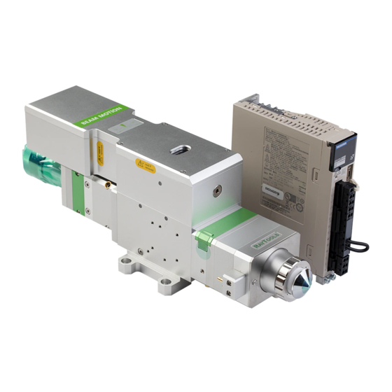
- Page 1 BM111 SERIES 3KW Auto-Focusing Laser Cutting Heads User Manual Hotline: 400-670-1510 Email: sales@empower.cn Add: 1500xinfei Road No.72, Shanghai, China...
- Page 2 Manual Thank you for choosing our products! This manual makes a detail introduction about the use of BM111 series auto-focusing laser cutting heads, including installation, operation and maintenance instructions etc. If you have other things need to know, please contact us directly.
-
Page 3: Table Of Contents
BM111 SERIES 3KW Auto-Focusing Laser Cutting Heads User Manual Index 1 Introduction ..........................4 1.1 Product Features ........................4 1.2 Structure & Function ......................4 2 Product Configuration ......................6 2.1 Configuration Type ........................ 6 2.2 Packing List ..........................6 2.3 Cutting Head Shape ....................... - Page 4 BM111 SERIES 3KW Auto-Focusing Laser Cutting Heads User Manual 5.2 Beam Focus position Adjustment ..................20 6 Maintenance .......................... 21 6.1 Cleaning Lens ........................21 6.2 Removal and Installation of Lens ..................21 6.2.1 Removal and Installation of Protective Lens ............22 6.2.2 Removal and Installation of Collimating Lens ............
-
Page 5: Introduction
This manual includes the general description, basic installation, factory settings, operation and maintenance services and other aspects of BM111 series products, which have too many optical and mechanical customization configurations, so only the main parts will be introduced in this manual. - Page 6 BM111 SERIES 3KW Auto-Focusing Laser Cutting Heads User Manual Focusing driver module: The collimating beam is focused into a small beam spot which has high power density, and the focus position is adjusted by the driving device automatically; ...
-
Page 7: Product Configuration
BM111 SERIES 3KW Auto-Focusing Laser Cutting Heads User Manual 2 Product Configuration 2.1 Configuration Type Code Fiber interface type Collimating lens type Focus lens type BM111A01A 100YYH 125YYH BM111A02A 100YYH 155YYH 2.2 Packing List Name Quantity Laser cutting head Driver... -
Page 8: Cutting Head Shape
BM111 SERIES 3KW Auto-Focusing Laser Cutting Heads User Manual 2.3 Cutting Head Shape QBH interface Cable interface Water-cooled X-Y adjust interface Protective Lens Cutting gas interface Nozzle-cooled gas interface Fig 2.1 – Cutting head shape of BM111 2.4 Cutting Head Configuration Diagram 2.4.1... -
Page 9: Focus Length
BM111 SERIES 3KW Auto-Focusing Laser Cutting Heads User Manual 2.4.2 Focus length 125mm FL 155mm FL Spacer parallel MODE BM111001A BM111002A CL/mm FL/mm H/mm 417.8 Weight/KG 6.28 8 | 28 V1.0 Shanghai Empower Technologies Co., Ltd. © Copy Right www.empower.cn... -
Page 10: Mechanical Installation
BM111 SERIES 3KW Auto-Focusing Laser Cutting Heads User Manual 3 Mechanical Installation 3.1 Mounting Holes The mounting holes size and position of the BM111 laser cutting head are shown in Figure 3.1, which can be used to fix the laser head and machine tool. We strongly recommend customers to install the laser head perpendicular to the process material surface as requested and make sure the laser head is locked, this is one of the preconditions to ensure the follow-up stable cutting effect. -
Page 11: Assist Gas Interface
BM111 SERIES 3KW Auto-Focusing Laser Cutting Heads User Manual used equipped with external water supplied, the precondition is to meet the requirements in the list. Water-cooled interface Water-cooled interface Nobble-cooled gas pipe interface Cutting gas pipe interface Fig 3.2 - position of water pipe and gas pipe interfaces... -
Page 12: Connection Of Cutting Head Cable
BM111 SERIES 3KW Auto-Focusing Laser Cutting Heads User Manual filters which can remove a minimum of 0.01 micron particle to purify. We recommend customers to use the pressure gauges with stainless steel diaphragm. Industrial pressure gauges suck in air. Rubber diaphragm produces hydrocarbons by aging or other factors. -
Page 13: Connection Of Cable And Driver
BM111 SERIES 3KW Auto-Focusing Laser Cutting Heads User Manual Motor cable interface Signal cable interface Fig 3.3 - cable interface of laser cutting head 3.3.2 Connection of Cable and Driver Connect motor power cable and signal cable with the corresponding interfaces of driver according to the definition in cable sleeve.(Note: The low level output of the limiting sensor is... -
Page 14: Fiber Insertion And Interface Direction Adjustment
BM111 SERIES 3KW Auto-Focusing Laser Cutting Heads User Manual 3.5 Fiber Insertion and Interface Direction Adjustment In this section, an optical fiber insertion method is described in conjunction with QBH connector. First, align the red point at the end of the QBH connector with the red point of the handwheel;... -
Page 15: Etc_F100 Installation
BM111 SERIES 3KW Auto-Focusing Laser Cutting Heads User Manual 4 ETC_F100 Installation 4.1 Interface and Signal 1.Interface Interface Description CON1 DB15 female connector, the interface to connect servo driver. CON2 Interface to connect external IO devices. CON3 Interface to 24V DC power supply. - Page 16 BM111 SERIES 3KW Auto-Focusing Laser Cutting Heads User Manual E1_A_P(Encoder A positive) E1_B_P(Encoder B positive) E1_C_P(Encoder C positive) Pin signals of the CON2 Interface: Description Alarm output When an abnormal alarm occurs, a high level signal is output, normally high impedance state...
- Page 17 BM111 SERIES 3KW Auto-Focusing Laser Cutting Heads User Manual place Focusing High-level control focus on, low-level control focus off enables Lower limit The lower limit of the input signal, active low Upper limit The upper limit of the input signal, active low Note: “N / A"...
-
Page 18: Wiring
BM111 SERIES 3KW Auto-Focusing Laser Cutting Heads User Manual 4.2 Wiring Fig 4.1 - ETC_F100 Wiring Instructions 17 | 28 V1.0 Shanghai Empower Technologies Co., Ltd. © Copy Right www.empower.cn... -
Page 19: Etc_F100 Dimensions
BM111 SERIES 3KW Auto-Focusing Laser Cutting Heads User Manual 4.3 ETC_F100 Dimensions Fig 4.2 - ETC_F100 Dimensions (Unit: mm) 18 | 28 V1.0 Shanghai Empower Technologies Co., Ltd. © Copy Right www.empower.cn... -
Page 20: Adjustment Of Beam Center And Focus Position
BM111 SERIES 3KW Auto-Focusing Laser Cutting Heads User Manual 5 Adjustment of Beam Center and Focus Position Beam Center Position Adjustment (QBH interface) Cutting quality in a great extent depends on whether the beam spot is in the center of nozzle or not. -
Page 21: Beam Focus Position Adjustment
BM111 SERIES 3KW Auto-Focusing Laser Cutting Heads User Manual 5.2 Beam Focus position Adjustment Even BM111 is equipped with automated focusing system, it still need dot manually to re-determine the focus position when users replace the lens or lasers. For details about operating system parameters, please refer to the system instructions. -
Page 22: Maintenance
BM111 SERIES 3KW Auto-Focusing Laser Cutting Heads User Manual 6 Maintenance 6.1 Cleaning Lens It’s necessary to maintain lens regularly because of the characteristic of laser cutting process. Once a weak cleaning the protective lens is recommended. The collimating lens and focusing lens need to be cleaned once every 2~3 month. -
Page 23: Removal And Installation Of Protective Lens
BM111 SERIES 3KW Auto-Focusing Laser Cutting Heads User Manual 6.2.1 Removal and Installation of Protective Lens The protective lens is a fragile part and needs to be replaced after damage. As shown in Figure 6.1, loosen two locking screws, hold the two sides of the drawer type lens mount and pull out the protective lens mount. -
Page 24: Removal And Installation Of Focusing Lens
BM111 SERIES 3KW Auto-Focusing Laser Cutting Heads User Manual Use a 3mm inner hexagon spanner loosen the screws of collimating components( as shown in figure 6.3), and seal the part(connected to collimating components) with Crepe Paper to prevent dust from falling inside the laser head. - Page 25 BM111 SERIES 3KW Auto-Focusing Laser Cutting Heads User Manual Protective lens module Laser head body Nozzle module M4 screws Slag-Block plate M4 screws M4 screws Fig 6.5 - Remove the protective lens and the nozzle component As shown in figure 6.6, use a lens removing tool to remove the focus lens mount.
-
Page 26: Replace Nozzle Connection Assembly
BM111 SERIES 3KW Auto-Focusing Laser Cutting Heads User Manual Focusing lens Spring pressure ring Focusing lens mount Fig 6.7 - Focus lens installation diagram Turn the focusing lens back into the focusing lens mount and tighten it. As the sequence shown in figure 1.1, reassemble and tighten the screws. -
Page 27: Replace Nozzle
BM111 SERIES 3KW Auto-Focusing Laser Cutting Heads User Manual 6.3.2 Replace Nozzle Screw the nozzle; Replace the new nozzle and re-tighten it properly. Once the nozzle or ceramic structure has to be replaced,it must be re-capacitance calibration. -
Page 28: Common Problems Analysis
BM111 SERIES 3KW Auto-Focusing Laser Cutting Heads User Manual alarm occurs, please note: 1) Z-axis travel setting is appropriate; 2) Whether the location of dial overtravel. 4. “Servo Alarm” Under normal circumstances, when the drive alarm, “Servo Alarm”will be displayed by ETC-F100. -
Page 29: Shanghai Empower Technologies Co., Ltd. © Copy Right
BM111 SERIES 3KW Auto-Focusing Laser Cutting Heads User Manual if the corresponding number is inverted, then the board is normal; For low effective input signal, 0V can be directly connected to the corresponding input port, if the corresponding number is inverted, then the board is normal.
Need help?
Do you have a question about the BM111 Series and is the answer not in the manual?
Questions and answers
I have a new RayTools laser cutting head bm111, but I have a problem with the focus being fixed and not moving.
To fix the focus issue on the Raytools BM111 laser cutting head, follow these steps:
1. Set the laser head scale to its maximum position.
2. Set the laser power to 80–100 watts.
3. Move the laser head in small steps (about 0.5 mm).
4. At each step, activate the laser to make a hole in textured paper.
5. Repeat dotting several times.
6. Compare the holes and find the position where the hole is smallest.
7. This position is the zero focus point, meaning the focus spot is at the nozzle end face.
This process is required when replacing the lens or laser, even though the system has auto-focusing.
This answer is automatically generated