
Related Manuals for Raytools BM115 Series


Summary of Contents for Raytools BM115 Series
- Page 1 BM115 SERIES 6-12KW Auto-Focusing Laser Cutting Head- User Manual Email: sales@raytools.ch Add: EMMENTALSTRASSE 96 CH-3414 OBERBURG, SWITZERLAND...
- Page 2 BM115 SERIES 6-12KW Laser Cutting Head User Manual Version V1.0 Date: 2017/12/14 Historical Version: History Date Change the profile Editors Reviewers Review date version V1.0 2018/8/22 Establish Thank you for choosing our product! This manual makes a detail introduction about the use of BM115 laser cutting head, including installation, setup, operation and service etc.
-
Page 3: Table Of Contents
BM115 SERIES 6-12KW Laser Cutting Head User Manual Index 1 Summary ..........................4 1.1 Structure ..........................4 2 Mechanical Installation ......................4 2.1 Mounting ..........................4 2.2 Connection of Water Pipe and Gas Pipe ................5 2.2.1 Water cooling interface ..................5 2.2.2 Assist gas interface .................... - Page 4 BM115 SERIES 6-12KW Laser Cutting Head User Manual 5.5.3 Z-axis coordinate drift ..................25 5.5.4 Input signal jitter or invalid ................25 3 | 27 www.raytools.ch...
-
Page 5: Summary
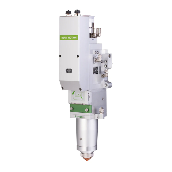
BM115 SERIES 6-12KW Laser Cutting Head User Manual 1 Summary 1.1 Structure BM115 laser cutting head includes fiber interface, collimation module, focus & beam alignment module, cover glass module and nozzle module which is shown in figure 1.1. Cable interface... -
Page 6: Connection Of Water Pipe And Gas Pipe
BM115 SERIES 6-12KW Laser Cutting Head User Manual Figure 2.1 — Mounting hole 2.2 Connection of Water Pipe and Gas Pipe 2.2.1 Water cooling interface BM115 laser cutting head is equipped with water cooling circuit for fiber interface, collimator and focus module which could be found in figure 2.2. It is important to note that when the laser power is greater than 500 watt, it is recommended to use water cooling. -
Page 7: Assist Gas Interface
BM115 SERIES 6-12KW Laser Cutting Head User Manual Outer diameter of water pipe caliber Minimum flow speed 1.8 l/min(0.48 gpm) Entry pressure 170-520kPa (30-60 psi) Entry temperature ≥room temperature />dew point <250mg/liter Hardness (relative to CaCO3) PH range 6 to 8... -
Page 8: Connection Of Cutting Head Cable
BM115 SERIES 6-12KW Laser Cutting Head User Manual CAUTION: Gas interface cannot be replaced arbitrarily, especially do not use PTFE TAPE, Otherwise, the gas path will be blocked and cannot do normal cutting which will damage cutting head at the same time. -
Page 9: Fiber Insertion And Interface Direction Adjustment
BM115 SERIES 6-12KW Laser Cutting Head User Manual fixation method. Please refer to corresponding instruction of fiber interface. WARNING: The optical components must be dust free and all dusts must be cleaned before use. The fiber shall be horizontally inserted into fiber interface to prevent dust from entering the interface and falling on the surface of the lens. -
Page 10: System Installation And Commissioning
BM115 SERIES 6-12KW Laser Cutting Head User Manual Locking screw Figure 2.5— Fiber insertion to QD The fiber insertion way is described as below by example of Q+. Firstly, to remove the dustproof cover and align the location pin of fiber end to U type slot of Q+ interface. -
Page 11: Interface & Signal
BM115 SERIES 6-12KW Laser Cutting Head User Manual 3.1.1 Interface & Signal Interface Descriptions CON1 DB15 female connector, interface to servo driver. CON2 Interface for connecting external IO devices. CON3 Interface to 24V DC power supply. CON4 Interface for connecting external IO devices. -
Page 12: Wiring
BM115 SERIES 6-12KW Laser Cutting Head User Manual Focus Output the position of current focus, is analog. Feedback Brake+ This signal is not connected (motor without brake) Note:N / A is an undefined interface, please leave it blank. Pins of CON4:... - Page 13 BM115 SERIES 6-12KW Laser Cutting Head User Manual Figure 3.1—ETC_F100 Wiring instruction 12 | 27 www.raytools.ch...
-
Page 14: Dimension Of Etc_F100
BM115 SERIES 6-12KW Laser Cutting Head User Manual Figure 3.2—limit diagram Note: Limit sensor is NPN-NC and outputs 0V continuously when it is not triggered. 3.1.3 Dimension of ETC_F100 Figure 3.3 —Overall size of ETC-F100 controller (unit: mm) 13 | 27... -
Page 15: Dimension Of Drive
BM115 SERIES 6-12KW Laser Cutting Head User Manual 3.1.4 Dimension of Drive Figure3.4 —Overall size of drive (unit: mm) 3.2 FSCUT (Cypcut) with position mode 3.2.1 Wiring The motor is AC servo motor, which should connect the end of the drive L1, L2 , L1C and L2C to AC 220V L and N. - Page 16 BM115 SERIES 6-12KW Laser Cutting Head User Manual Figure3.5 — Position loop FSCUT wiring diagram BM115 achieves the auto focus by movement of collimation lens group and the focus adjustment range & pulse rate are based on movement of collimation lens. When the collimation lens moves 1mm, it conducts the movement of focus point by 2.25mm or 4mm.
- Page 17 BM115 SERIES 6-12KW Laser Cutting Head User Manual 22mm -22mm 4.4mm · 35mm/s 22mm 35mm/s 1500mm/s Figure 3.6 — Platform configuration tools (BM115, CL100:FL150) 16 | 27 www.raytools.ch...
-
Page 18: Beam Adjustments And Focusing
BM115 SERIES 6-12KW Laser Cutting Head User Manual -44mm 44mm 8.8mm · 35mm/s 44mm 35mm/s 1500mm/s Figure 3.7 — Platform configuration tools (BM115, CL100:FL200) 4 Beam Adjustments and Focusing 4.1 Beam Adjustments (QBH interface) Cutting quality in a great extent depends on whether the lens is in the middle. If the lens is not in the middle, the laser beam may contact with nozzle or inner wall to produce high temperature deformation. -
Page 19: The Focus Position Adjustment
BM115 SERIES 6-12KW Laser Cutting Head User Manual X-Y Adjusting screw Dustproof Cover Figure 4.1— Beam adjustment Pick a scotch tape, flatten it, and attach it to the nozzle tip; Open the inner guiding red light of the laser. Find and observe the position of nozzle center that the red light in the scotch tape relative to;... -
Page 20: Removal And Installation Of Lenses
BM115 SERIES 6-12KW Laser Cutting Head User Manual Cleaning to the cover glass once a week is recommended. The collimating lenses and focusing lenses are recommended to be cleaned once every 2~3 months. In order to facilitate the maintenance of the cover glass, the cover glass holder adopts a drawer type structure. (Figure 5.1) -
Page 21: Removal And Installation Of Top Cover Glass
BM115 SERIES 6-12KW Laser Cutting Head User Manual Install the pressing ring. Insert the cover glass holder back to the laser processing head and fasten the buckle. Pressing ring Cover glass Cover glass holder Seal ring Figure 5.2 — Structure of cover glass holder Attention: It is not allowed to pull out the edge of seal ring directly as it is very easy to damage the elastic seal ring. -
Page 22: Removal And Installation Of Collimating Lenses
BM115 SERIES 6-12KW Laser Cutting Head User Manual Re-insert the cover glass holder to the laser processing head and tighten the locking screw. Note: It is not allowed to pull out the edge of seal ring directly as it is very easy to damage the elastic seal ring. -
Page 23: Removal And Installation Of Focus Lenses
BM115 SERIES 6-12KW Laser Cutting Head User Manual 5.2.4 Removal and Installation of Focus Lenses Removal and installation of focus lenses refer to the following steps: Remove the laser head and move to a dust free room. Clean all dusts on the laser head surface;... -
Page 24: Replace Ceramic Body
BM115 SERIES 6-12KW Laser Cutting Head User Manual In the laser cutting process, the laser head will inevitably be hit. So it is necessary to replace the nozzle connector. 5.3.1 Replace Ceramic Body Unscrew the nozzle; Press the ceramic body to make it fixed and not oblique and then screw off the fastener;... -
Page 25: Common Problem Analysis
BM115 SERIES 6-12KW Laser Cutting Head User Manual 2. Whether the sensor is obscured by unknown objects;; 3. Limit sensor installed improperly (this possibility is minimal); 4. The limit signal is disturbed. At this time, the corresponding limit signal may flicker in the function test, especially after the machine tool is enabled. -
Page 26: The Screen Is Abnormally Displayed
BM115 SERIES 6-12KW Laser Cutting Head User Manual The dial position near the up limit (about 1mm), this situation will occur when servo calibrating. In the event of the above problems, please jog the focus to the middle of the stroke (more than 1mm), and then execute servo calibration.
Need help?
Do you have a question about the BM115 Series and is the answer not in the manual?
Questions and answers