Advertisement
Solid State Relays
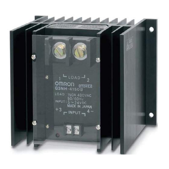
G3NH
Refer to Warranty and Application Considerations (page 1), Safety
Precautions (page 4), and Technical and Safety Information (page 6).
Switching 75 to 150 A at 240 to 440 VAC
• Easy-to-mount monoblock construction incorporating heat sink.
• Replaceable power cartridge.
• Built-in operation indicator and varistor.
• A series of high-voltage (440 V) models available.
Model Number Structure
Model Number Legend
G3NH-@@@@
1
2 3 4 5
1. Basic Model Name
G3NH:
Solid State Relay
2. Rated Load Power Supply Voltage
2:
200 VAC
4:
400 VAC
3. Rated Load Current
075:
75 A
150:
150 A
4. Terminal Type
B:
Screw terminals
5. Zero Cross Function
Blank:
Equipped with zero cross function
Ordering Information
List of Models
Isolation
Zero cross
function
Photocoupler
Yes
The built-in Thyristor Modules can be replaced. Refer to the table on page 200 for the model number.
Note: When ordering, specify the rated input voltage.
198
Solid State Relays
Indicator
Rated output load
Yes
75 A at 100 to 240 VAC
75 A at 180 to 440 VAC
150 A at 100 to 240 VAC
150 A at 180 to 440 VAC
G3NH
Rated input voltage
5 to 24 VDC
G3NH-2075B
100 to 240 VAC
G3NH-4075B
G3NH-2150B
G3NH-4150B
Model
Advertisement
Table of Contents

Related Manuals for Omron G3NH


Summary of Contents for Omron G3NH
- Page 1 150 A at 100 to 240 VAC G3NH-2150B 150 A at 180 to 440 VAC G3NH-4150B The built-in Thyristor Modules can be replaced. Refer to the table on page 200 for the model number. Note: When ordering, specify the rated input voltage. G3NH Solid State Relays...
-
Page 2: Specifications
1,800 A (60 Hz, 1 cycle) G3NH-4150B 180 to 440 VAC 150 to 484 VAC Note: The load current varies depending on the ambient temperature. Refer to Load Current vs. Ambient Temperature under Engineering Data for details. Characteristics Item G3NH-2075B... -
Page 3: Engineering Data
Engineering Data Load Current vs. Ambient Temperature One Cycle Surge Current: Non- repetitive Note: Keep the inrush current to half the rated value if it occurs repeatedly. G3NH-@075B, G3NH-@150B G3NH-@075B, G3NH-@150B G3NH-@150B Vertical mounting G3NH-@150B Horizontal mounting Vertical mounting G3NH-@075B... - Page 4 Assembly of the thyristor module must be performed in the exact reverse order of the previous disassembly steps 1 to 5. 2. Remove the four screws (shown in the following as “B”) and the nameplate from the relay housing. 6. Before mounting the new thyristor module for replacement, wipe...
-
Page 5: Safety Precautions
Dimensions Note: All units are in millimeters unless otherwise indicated. The orientation indicated by the external dimensions is not the correct mounting orientation. When opening mounting holes, refer to the mounting hole dimensions. G3NH-2075B/4075B Four, 6.5-dia. Mounting Holes Four, 6.5 dia. or M6 135 0.5...
Need help?
Do you have a question about the G3NH and is the answer not in the manual?
Questions and answers