Table of Contents
Advertisement
Quick Links
Advertisement
Table of Contents

Related Manuals for Autel MaxiDAS DS900-TS


Summary of Contents for Autel MaxiDAS DS900-TS
- Page 1 MaxiDAS DS900-TS...
- Page 2 Autel will not be liable for any direct, special, incidental, or indirect damages, or for any economic consequential damages (including the loss of profits) as a result of using this product.
- Page 3 The safety messages herein cover situations Autel is aware of at the time of publication. Autel cannot know, evaluate or advise you as to all of the possible hazards. You must be certain that any condition or service procedure encountered does not jeopardize...
- Page 4 DANGER When an engine is operating, keep the service area WELL VENTILATED or attach a building exhaust removal system to the engine exhaust system. Engines produce carbon monoxide, an odorless, poisonous gas that causes slower reaction time and can lead to serious personal injury or loss of life. SAFETY WARNINGS Always perform automotive testing in a safe environment.
-
Page 5: Table Of Contents
CONTENTS 1 USING THIS MANUAL ..................... 1 ..................... 1 ONVENTIONS 1.1.1 Bold Text ...................... 1 1.1.2 Notes and Important Messages ..............1 1.1.3 Hyperlinks ..................... 1 1.1.4 Illustrations ....................2 1.1.5 Procedures ....................2 2 GENERAL INTRODUCTION .................... 3 DAS DS900-TS T ................ - Page 6 ..................20 EHICLE DENTIFICATION 4.3.1 Auto Detect ....................20 4.3.2 Manual Input ....................21 4.3.3 Scan VIN/License ..................21 4.3.4 Menu Vehicle Selection ................22 4.3.5 OBDII Direct Entry ..................22 ....................... 23 AVIGATION 4.4.1 Diagnostic Screen Layout ................23 4.4.2 Screen Messages ..................
- Page 7 (DPF) S ............51 IESEL ARTICLE ILTER ERVICE (IMMO) S ................52 MMOBILIZER ERVICE 6 TPMS ..........................54 ..................... 54 ETTING TARTED 6.1.1 TPMS Service Menu Layout ............... 54 ............... 55 ONNECTING ABLET TO EHICLE ................... 55 EHICLE ELECTION 6.3.1 Auto Detect ....................
- Page 8 6.8.4 Copy Relearn ....................78 TPMS OEM P NO.................. 80 6.9.1 Application Scenarios ................. 80 6.9.2 Operations ....................80 7 TOOLKIT ......................... 85 8 TPMS RETROFIT......................86 9 VCI MANAGER ....................... 88 VCI B ................... 89 LUETOOTH AIRING BAS B ..................
- Page 9 15.4 ......................122 RAINING 15.5 FAQ ....................... 122 16 MAXIVIEWER ......................123 17 MAXIVIDEO ........................ 125 18 QUICK LINK ....................... 126 19 AUTEL USER CENTER ....................127 20 MAINTENANCE AND SERVICE................. 129 20.1 ................129 AINTENANCE NSTRUCTIONS 20.2 ................. 130...
- Page 10 20.3 ................... 130 BOUT ATTERY SAGE 20.4 ..................131 ERVICE ROCEDURES 20.4.1 Technical Support ..................131 20.4.2 Repair Service ..................133 20.4.3 Other Services ..................133 21 COMPLIANCE INFORMATION .................. 134 22 WARRANTY ....................... 136...
-
Page 11: Using This Manual
Using This Manual This manual contains device usage instructions. Some illustrations shown in this manual may make reference to modules and optional equipment that are not included in your system. Contact your sales representative for availability of other modules and optional tools or accessories. 1.1 Conventions The following conventions are used: 1.1.1 Bold Text... -
Page 12: Illustrations
1.1.4 Illustrations Illustrations used in this manual are samples; the actual testing screen may vary for each vehicle being tested. Observe the menu titles and on-screen instructions to make correct option selection. 1.1.5 Procedures An arrow icon indicates a procedure. Example: ➢... -
Page 13: General Introduction
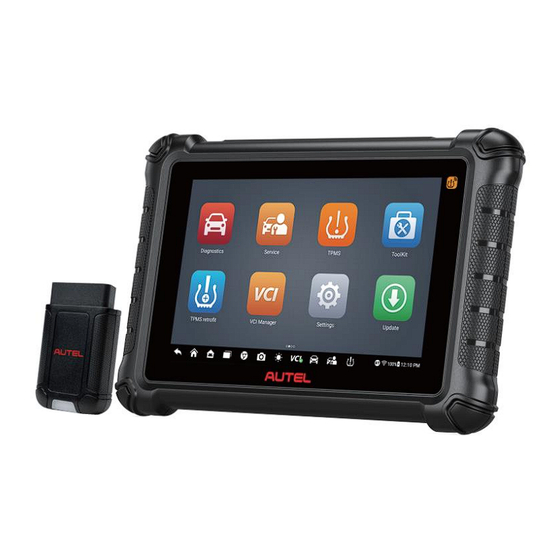
⚫ data. This manual describes the construction and operation of both devices and how they work together to deliver diagnostic solutions. 2.1 MaxiDAS DS900-TS Tablet 2.1.1 Function Description Figure 2-1 Tablet Front View 8.0” LCD Touchscreen Ambient Light Sensor — detects ambient light brightness. - Page 14 The power LED displays green, yellow, or red depending on power level and operating state. A. Green ⚫ Illuminates green when the tablet is charging and the battery level is above 90%. ⚫ Illuminates green when the tablet is powered on and the battery level is above 15%.
-
Page 15: Power Sources
Figure 2-3 Tablet Top View USB Type-C Charging Port Mini SD Card Slot 10. USB Port 11. Power/Lock Button — turns the device on/off with long press, or locks the screen with short press. 2.1.2 Power Sources The tablet can receive power from any of the following sources: Internal Battery Pack ⚫... - Page 16 Item Description Memory 4 GB RAM & 64 GB ROM Display 8-inch LCD screen with 1280 x 800 resolution Rear Camera 8 MP USB Type-C ⚫ USB 2.0 ⚫ Wi-Fi Connectivity ⚫ Bluetooth ⚫ Mini SD card (supports up to 64 GB) ⚫...
-
Page 17: Maxivci V150
Item Description ISO9141-2, ISO14230-2, ISO15765, K/L-Line, Flashing Code, SAE-J1850 VPW, SAE-J1850PWM, ISO11898 (High-speed, Protocols Middle-speed, Low-speed and Single-wire CAN, fault-tolerant CAN), SAE J2610, GM UART, UART Echo Byte Protocol, Honda Diag-H Protocol, TP2.0, TP1.6, ISO13400, CAN FD 2.2 MaxiVCI V150 MaxiVCI V150 is a small vehicle communication interface (VCI) that wirelessly connects to the tablet and vehicle’s data link connector (DLC) for vehicle data transmission. -
Page 18: Power Source
Table 2-2 Power/Connection LED Color Description Green Lights solid green when powered on. Lights solid blue when the device is successfully connected via Bluetooth Blue but is not communicating with the vehicle. Flashes blue when the device is Flashing successfully connected via Bluetooth Power/Connection Blue and is communicating with the vehicle. -
Page 19: Other Accessories
Item Description Dimensions 77.47 x 46.8 x 21.38 mm (3.05” x 1.84” x 0.84”) (L x W x H) Weight 51.5 g (0.11 lbs) 2.3 Other Accessories External Power Adapter Together with the USB Type-C cable, connects the tablet to the external DC power port for power supply. -
Page 20: Getting Started
Getting Started Ensure the tablet is sufficiently charged or is connected to an external power supply. (See Power Sources.) NOTE The images and illustrations depicted in this manual may differ slightly from those in the most recent product. 3.1 Powering Up Long press the Power/Lock button on the top-right side of the tablet to power on the unit. -
Page 21: Application Buttons
NOTE The tablet screen is locked by default when first powered on. We recommend you lock the screen to protect the information in the system and conserve the power. The touchscreen navigation is menu-driven, enabling quick access to functions and features by tapping on the buttons on the screen. - Page 22 Manages the permissions for unlocking the OE gateway. Authorization Launches the Support platform which synchronizes Support Autel’s online service base station with the MaxiDAS tablet. See Support. Provides quick search for the supported functions and MaxiViewer vehicles of Autel diagnostic tools. See MaxiViewer.
-
Page 23: Locator And Navigation Buttons
Name Description MaxiTools Includes log collection and factory data reset two parts. Allows you to register an account, view and edit your Autel User personal profile and link your device. See Autel User Center Center. 3.1.2 Locator and Navigation Buttons Operations of the navigation buttons at the bottom of the screen are described in the table below. -
Page 24: System Status Icons
Button Name Description Display Supports the display brightness automatically or manually Brightness adjustment. Opens the VCI Manager application. The BT badge at the bottom-right corner indicates the tablet is communicating Manager with the VCI device. An “X” badge will display at the Shortcut bottom-right corner if the tablet is not connected to the VCI device. -
Page 25: Powering Down
3.2 Powering Down All vehicle communications must be terminated before shutting down the tablet. A warning message appears if you attempt to shut down the tablet while it is communicating with the vehicle. Forcing a shut-down while communicating may lead to ECU problems on some vehicles. -
Page 26: Diagnostics
Diagnostics The Diagnostics application can retrieve ECU information, read & erase DTCs, and view live data. The Diagnostics application can access the electronic control unit (ECU) for various vehicle control systems, including engine, transmission, antilock brake system (ABS), and airbag system (SRS). 4.1 Establishing Vehicle Communication Prior to performing the Diagnostics function, ensure the tablet is connected to the test vehicle through the MaxiVCI V150. -
Page 27: No Communication Message
A BT badge will display at the bottom-right corner of the VCI Manager shortcut, which means the communication of MaxiVCI V150 and MaxiDAS tablet has been established, and the tablet is ready to start vehicle diagnosis. Refer to VCI Bluetooth Pairing for details. -
Page 28: Getting Started
Incorrect vehicle identification was entered. ⚫ 4.2 Getting Started Ensure a communication link is established between the test vehicle and tablet via the MaxiVCI V150. 4.2.1 Vehicle Menu Layout When the tablet is properly connected to the vehicle, the platform is ready to start vehicle diagnosis. - Page 29 Table 4-1 Top Toolbar Buttons Button Name Description Home Returns to the MaxiDAS Job Menu. Provides a fast way to identify the test vehicle. Vehicle Identification for details. Displays all the vehicle manufacturers. Adds your preferred vehicle manufacturers into Favorites favorites.
-
Page 30: Vehicle Identification
4.3 Vehicle Identification The MaxiDAS diagnostics system supports five methods for vehicle identification: Auto Detect Manual Input Scan VIN/License Manual Vehicle Selection OBDII Direct Entry 4.3.1 Auto Detect The MaxiDAS diagnostics system features the latest VIN-based Auto Detect function to identify vehicles and scan all the diagnosable ECUs and run diagnostics on the selected system. -
Page 31: Manual Input
4.3.2 Manual Input For vehicles not supporting the Auto Detect function, you may manually enter the VIN. ➢ To perform Manual Input Tap the Diagnostics application button from the MaxiDAS Job Menu. The Vehicle Menu displays. Tap the VID button on the top toolbar to open the dropdown list. Select Manual Input. -
Page 32: Menu Vehicle Selection
Figure 4-3 Scan VIN/License If the VIN or license number cannot be scanned, you can input manually. Tap button on the bottom-right corner of the screen to display the screen for manually input. After entering the correct VIN, tap OK to continue. Follow the on-screen instructions to complete the operation and advance to the vehicle Diagnostics Menu screen. -
Page 33: Navigation
4.4 Navigation After the test vehicle is identified, the Diagnostic Menu screen will appear. This section consists of various commonly used functions, including Auto Scan and Control Unit. The available functions displayed vary depending on the test vehicle. 4.4.1 Diagnostic Screen Layout Figure 4-4 Diagnostic Menu Screen The Diagnostic Menu screen typically includes four sections: Diagnostics Toolbar... - Page 34 When encountering Data an error during testing and diagnosing, use this Logging function to contact Autel’s technical staff for solutions. See Data Logging for details. ➢ To print data in Diagnostics Tap the Diagnostics application button from the MaxiDAS Job Menu. The Print button on the diagnostic toolbar is available throughout the whole diagnostics operations.
-
Page 35: Screen Messages
4.4.1.2 Status Information Bar The status information bar at the top of the main section may display the following items: Menu Title — displays the menu heading of the main section. VCI Icon — displays the VCI connection status. Voltage Icon — displays the vehicle’s voltage status. 4.4.1.3 Main Section The main section of the screen varies according to the stage of operations, which may... -
Page 36: Making Selections
4.4.3 Making Selections The Diagnostics application is a menu-driven program that presents a series of choices. Once a selection has been made, the next menu in the series is displayed. Each selection narrows the focus and leads to the desired test. Tap the screen to make menu selections. - Page 37 Navigation Bar Main Section Function Buttons 4.5.1.1 Navigation Bar List Tab — displays the scanned data in list format. Progress Bar — indicates the test progress. 4.5.1.2 Main Section Column 1 — displays the sequence numbers. Column 2 — displays the scanned systems. Column 3 —...
-
Page 38: Control Unit
Name Description Returns to the previous screen or exits Auto Scan. 4.5.2 Control Unit The Control Unit function allows you to manually locate a required control system for testing through a series of choices. Follow the menu-driven procedures and make proper selections. -
Page 39: Ecu Information
NOTE The diagnostics toolbar functions such as saving and printing of test results can be performed throughout the whole diagnostic testing. Data logging and help information are also available. ➢ To perform a diagnostic function Establish communication with the test vehicle. Identify the test vehicle by selecting from the menu options. -
Page 40: Trouble Codes
4.6.2 Trouble Codes Read Codes This function retrieves and displays the DTCs from the vehicle’s control system. The Read Codes screen varies for each vehicle being tested. On some vehicles, freeze frame data can also be retrieved for viewing. Figure 4-8 Trouble Codes Screen Diagnostics Toolbar Buttons —... -
Page 41: Live Data
Erase Codes After reading the retrieved codes and making appropriate vehicle repairs, use this function to erase vehicle codes. ➢ To erase codes Tap Erase Codes from the Trouble Codes screen. A warning message displays to inform you of data clearing when this function is applied. - Page 42 Diagnostics Toolbar Buttons — tap the drop-down button at the top center of the screen and the diagnostic toolbar buttons display. See Table 4-2 Diagnostics Toolbar Buttons for detailed descriptions of the operations for each button. Main Section Name Column — displays the parameter names. ⚫...
- Page 43 Each parameter item displays the selected mode independently. ◆ Analog Gauge Mode — displays the parameters in gauge charts. ◆ Text Mode — the default mode that displays the parameters as a text list. NOTE Status parameters, such as a switch reading like ON, OFF, ACTIVE, and ABORT, can only be displayed in Text Mode.
- Page 44 Full Screen Display — this option is only available in the waveform graph mode, and mostly used in Graph Merge status for data comparison. There are four control buttons available on the top-right side of the screen under this mode. Scale Button —...
- Page 45 function will be executed and the device will automatically record and save the generated data. You can review the saved live data by tapping the Review button at the bottom of the screen. Tap the drop-down button on the right side of the parameter name to open a submenu.
- Page 46 When the trigger is successfully set, a trigger mark will display in front of the parameter name. The mark is gray when it is not triggered, and displays orange when triggered. Moreover, two horizontal lines display on each of the data graphs (when Waveform Graph Mode is applied) to indicate the alarm point.
- Page 47 ➢ To set live data record duration Tap the Setting button at the bottom of the Live Data screen. Tap the “>” button to the right of Recording Time After Trigger bar and select a time length. Tap OK to save the setting and return to the Live Data Setting screen; or tap the “X”...
-
Page 48: Active Test
Show Selected — displays the selected parameters. ⚫ Graph Merge — merges selected data graphs. ⚫ Back — exits the review and returns to the Live Data screen. ⚫ Back — returns to the previous screen or exits the function. 4.6.4 Active Test The Active Test function is used to access vehicle-specific subsystem and component tests. -
Page 49: Generic Obdii Operations
4.7 Generic OBDII Operations This option presents a quick way to check for DTCs, isolate the cause of an illuminated Malfunction Indicator Lamp (MIL), check monitor status prior to emissions certification testing, and perform a number of other services that are emissions-related. The OBD direct access option is also used for testing OBDII/EOBD compliant vehicles that are not included in the database. -
Page 50: Function Descriptions
Figure 4-14 OBDII Diagnostic Menu Select a function to continue. DTC & FFD ⚫ I/M Readiness ⚫ Live Data ⚫ O2 Sensor Monitor ⚫ On-Board Monitor ⚫ Component Test ⚫ Vehicle Information ⚫ Vehicle Status ⚫ NOTE The supported functions may vary by vehicles. 4.7.2 Function Descriptions This section describes the various functions of each diagnostic option: 4.7.2.1... - Page 51 Stored Codes ⚫ Stored codes are the current emissions-related DTCs from the ECU of the vehicle. OBDII/EOBD codes have a priority according to their emission severity, with higher priority codes overwriting lower priority codes. The priority of the code determines the illumination of the MIL and the codes erase procedure.
- Page 52 Since DTCs Cleared — displays the status of monitors since the last time the ⚫ DTCs are erased. This Driving Cycle — displays the status of monitors since the beginning of the ⚫ current drive cycle. 4.7.2.3 Live Data This function displays the real time PID data from ECU. Displayed data includes analog inputs and outputs, digital inputs and outputs, and system status information broadcast on the vehicle data stream.
-
Page 53: Diagnostic Reports
4.8 Diagnostic Reports 4.8.1 Pre-Scan and Post-Scan Functions After performing pre-scan and post-scan functions by entering the same maintenance order number, tap Data Manager > Vehicle History to select the historical test record named with the maintenance order number. Both the pre-scan results and post-scan results will be displayed in the same historical test record, which can be generated as a PDF report for easily comparing the changes between pre-scan and post-scan. -
Page 54: Diagnostics Report Saving, Viewing, And Sharing
4.8.2 Diagnostics Report Saving, Viewing, and Sharing The diagnostic report can be reviewed, saved, and shared with others through many ways. 4.8.2.1 Diagnostics Report Saving Via the History function ⚫ Enter the main screen of the Diagnostics application, and tap History on the top toolbar. - Page 55 Tap Get Report. Enter the license plate and current mileage. Tap Save. Via the Auto Scan function ⚫ Tap Auto Scan from the Diagnostic Menu screen. The tablet will scan the ECU automatically. Figure 4-17 Select Auto Scan Screen When the system scan is completed, tap Report from the function buttons at the bottom of the screen.
- Page 56 Once you saved the reports by tapping the Save All Data button, tap Data Manager > PDF to view these reports. Once you saved the reports by tapping the Get Report or Save Report button, tap Data Manager > Cloud Report to view these reports saved to the Autel cloud platform.
-
Page 57: Exiting Diagnostics
4.8.2.3 Diagnostics Report Cloud Sharing Tap Data Manager > Cloud Report to enter the Report List screen. Figure 4-20 Report List Screen NOTE Note that if the report displays , it means the report has been uploaded to the cloud successfully, and you can share the report with others;... - Page 58 ➢ To exit the Diagnostics application On an active diagnostic screen: Tap the Back or ESC button to exit a diagnostic session step by step. Or tap the Vehicle Swap button on the Diagnostics Toolbar to return to the Vehicle Menu screen. On the Vehicle Menu screen: Tap the Home button on the top toolbar.
-
Page 59: Service
Service The Service application is specially designed to provide quick access to the vehicle systems for various scheduled service and maintenance tasks. The typical service operation screen is a series of menu-driven executive commands. Follow on-screen instructions to select appropriate execution options, enter correct values or data, and perform necessary actions. -
Page 60: Epb Safety
✓ been completed. NOTE Autel accepts no responsibility for any accident or injury arising from the maintenance of the Electric Parking Brake system. 5.3 Tire Pressure Monitoring System (TPMS) Service This function allows you to quickly look up the tire sensor IDs from the vehicle’s ECU, as well as to perform TPMS replacement and reset procedures after tire sensors are replaced. -
Page 61: Steering Angle Sensor (Sas) Service
Accident repairs where damage to the steering angle sensor, SAS assembly, or any part of the steering system may have occurred. NOTE Autel accepts no responsibility for any accident or injury arising from servicing the SAS system. When interpreting DTCs retrieved from the vehicle, always follow the manufacturer’s recommendation for repair. -
Page 62: Immobilizer (Immo) Service
driven more with higher load and speed. In order for regeneration to take place, a prolonged high exhaust temperature must be obtained. In the event of the car being driven in such a way that regeneration is not possible, i.e., frequent short journeys, a diagnostic trouble code will eventually be registered in addition to the DPF light and “Check Engine”... - Page 63 frequency identification between a transponder in the ignition key and a radio frequency reader in the steering column. When the key is placed in the ignition, the transponder sends a signal with a unique identification code to the reader, which relays it to a receiver in the vehicle's computer control module.
-
Page 64: Tpms
TPMS The TPMS application supports TPMS sensors including BLE sensors which are compatible with Tesla vehicles. Relying on this application, you can check the TPMS sensor conditions, program the MX-Sensor, and perform the TPMS Relearn procedure and other basic TPMS diagnostic functions. 6.1 Getting Started 6.1.1 TPMS Service Menu Layout Tap TPMS on the MaxiDAS Job Menu. -
Page 65: Connecting Tablet To Vehicle
Button Name Description Displays the stored test vehicle history records. History Vehicle History for details. Tap the drop-down button to select the correct market, then the vehicle manufacturer icons of the selected market will be displayed. Market Note: Please double check whether the market is selected correctly if the vehicle cannot be found. -
Page 66: Auto Detect
6.3.1 Auto Detect For vehicles supporting the Auto Detect function, you can acquire the VIN information to quickly identify the exact vehicle with just one tap. ➢ To perform Auto Detect in TPMS application Tap the TPMS application button from the MaxiDAS Job Menu. The Vehicle Menu displays. -
Page 67: Scan Vin/License
6.3.3 Scan VIN/License MaxiDAS tablet also supports identifying the vehicle by scanning its VIN or license number. Using this vehicle identification method will automatically turn on the camera system. ➢ To perform Scan VIN/License in TPMS application Tap the TPMS application button from the MaxiDAS Job Menu. The Vehicle Menu displays. - Page 68 Figure 6-3 Vehicle Model Selection Figure 6-4 Vehicle Year Selection The following screen may display for vehicles using Indirect TPMS.
- Page 69 Figure 6-5 Indirect TPMS Selection Screen For indirect TPMS vehicle, only the Relearn function is supported. Tap the vehicle year information button, in the case of the above screen — 2008/08-2019/12 (indirect), to display the Relearn Procedure screen. Follow the on-screen instructions to complete the operation.
-
Page 70: Tpms Service Screen Layout
Figure 6-7 TPMS Service Screen 6.4 TPMS Service Screen Layout The TPMS Service screen typically includes four sections: Figure 6-8 TPMS Service Screen Top Toolbar Buttons Navigation Tab Main Section Function Buttons... -
Page 71: Top Toolbar Buttons
6.4.1 Top Toolbar Buttons The top toolbar contains a number of buttons. See Table 4-2 Diagnostics Toolbar Buttons for details. 6.4.2 Navigation Tab The navigation tab at the top of the main section contains the following items: Check Tab — displays the triggered sensor data. Diagnostics Tab —... - Page 72 Figure 6-9 Check Screen Sensor ID Tire Pressure Sensor Frequency Tire Temperature Sensor Battery Status Low Battery Icon Successfully Triggered NOTE The default check order on the tablet is LF (left front), RF (right front), RR (right rear), and LR (left rear). The wheel positions correspond with the descriptions on the right of the screen.
- Page 73 ➢ To check the sensors Select the Check tab. Tap the desired wheel position on the vehicle thumbnail. Hold the part of the tablet marked with TPMS service symbol close to the tire sidewall near the valve stem, and then tap the Trigger button. The tablet will send low frequency signal to trigger the sensor.
-
Page 74: Tpms Diagnostics
6.6 TPMS Diagnostics The Diagnostics function is used to check the status of the TPMS system. This function requires connection with the test vehicle. Refer to Establishing Vehicle Communication for details. ➢ To perform TPMS diagnostics function Tap the Diagnostics tab. The tablet will automatically communicate with the vehicle. -
Page 75: Dtc Details
Sensor IDs Retrieved by Activation Sensor IDs Retrieved by OBD — saved in the TPMS ECU DTCs Retrieved by OBD — existed in the TPMS ECU NOTE If the OBD function is supported by the test vehicle, the sensor ID saved in the TPMS ECU will be retrieved and displayed on the screen with an OBD mark before it when the communication is completed. -
Page 76: Retry Diagnosis
If no DTCs are present in the TPMS ECU, a green “No DTC” message will display in the DTC column. Figure 6-13 No DTC Screen 6.6.2 Retry Diagnosis Tap Retry Diagnosis to establish communication with the ECU again and to retrieve sensor IDs and DTCs present in the ECU. -
Page 77: Service Function
Figure 6-14 Live Data Screen All the parameters displayed on the Live Data screen are default values. Check box before the parameters you want to see, the Show Selected icon on the bottom of the screen will be available and turn blue. Tap Show Selected and the selected parameters will be displayed in a separate screen. -
Page 78: Sensor Programming
The Programming function is used to program the sensor data to the MX-Sensor and replace the faulty sensor (poor battery life or malfunction). NOTE Programming function will only work with Autel MX-Sensor. The 1-Sensor (Press-in) is taken as an example in this manual. Please choose the proper MX-Sensor when programming. - Page 79 As shown in the screen above, there are four options available when programming MX-Sensor: Copy by Activation, Copy by OBD, Copy by Input, and Auto Create 1-20 Sensors. The main section of the screen may include: Column 1 — displays wheel positions. ⚫...
-
Page 80: Copy By Activation
Figure 6-18 Programming Screen 2 6.7.1 Copy by Activation This function allows the user to copy the retrieved sensor ID from the activated sensor to the new MX-Sensor. It is used after the original sensor is triggered. ➢ To copy by activation After performing TPMS check (see TPMS Check for details), the trigger marks... - Page 81 Select the corresponding wheel, then tap Copy by Activation. Place the MX-Sensor near the TPMS antenna of the tablet and tap OK to start programming the retrieved sensor ID to the MX-Sensor. Figure 6-20 Copy by Activation Screen Figure 6-21 Copy by Activation Complete Screen When the programming is complete, the programmed ID will display in the column to the right of the wheel designation.
-
Page 82: Copy By Obd
NOTE If the IDs of the original sensor and the new MX-Sensor are the same and the ID is already registered to the vehicle ECU, there is no need to perform the Relearn function when the new programmed sensor has been installed to the same wheel. If the IDs retrieved from sensor activation and those registered to the TPMS ECU are different, tap Copy by OBD to program the IDs saved in the ECU to the new MX-Sensor. -
Page 83: Copy By Input
6.7.3 Copy by Input The Copy by Input function allows users to program a new MX-Sensor with the ID of an original TPMS sensor. ➢ To copy by input Select one sensor position and place an MX-Sensor near the TPMS antenna of the tablet, then tap Copy by Input to program the new MX-Sensor. -
Page 84: Tpms Relearn
➢ To auto create 1-20 sensors Select the vehicle model, and select a wheel location on the screen and place the MX-Sensor(s) near the TPMS antenna of the tablet. Tap Auto Create 1-20 Sensors to program the new MX-Sensor. When the programming is complete, the programmed ID will display in the table on the screen. -
Page 85: Obd Relearn
6.8.1 OBD Relearn OBD Relearn is completed via the OBD diagnostic function without needing to drive, and the relearn procedures are basically the same for different models. Thus, we highly recommend you use this efficient and time-saving relearn method. The OBD Relearn function allows the MaxiDAS tablet to directly write the TPMS sensor IDs into the TPMS module. -
Page 86: Automatic Relearn
Figure 6-26 OBD Relearn Screen 2 6.8.2 Automatic Relearn Automatic Relearn requires driving to complete. For some vehicle models, the Automatic Relearn procedures can be completed directly by driving, while for some vehicle models, you need to follow the on-screen Learning Process Guide to let the vehicle enter the Automatic Relearn mode before driving. -
Page 87: Stationary Relearn
Figure 6-28 Automatic Relearn Screen 2 6.8.3 Stationary Relearn Stationary Relearn can be completed without relying on driving and OBD diagnostics. To activate this mode, it is usually necessary to perform a series of operations to let the vehicle enter the relearn mode first, then use TPMS tools to perform activation or deflation to complete the relearn. -
Page 88: Copy Relearn
Copy Relearn is to clone the sensor ID and tire location. Before performing Copy Relearn, you need to first obtain the sensor ID and tire location needed to be cloned, then use Autel tool to clone and program the sensor ID, and install the sensor to the corresponding tire to complete Copy Relearn. - Page 89 NOTE Ensure the original sensor will not interfere with the relearn procedures. It is recommended that you keep the original sensor at least 100 meters away from the vehicle or put the sensor in an enclosed metal box to avoid signal interference. Normally, it is not necessary to perform relearn procedures after cloning.
-
Page 90: Tpms By Oem Part No
6.9 TPMS by OEM Part NO. If the sensor’s OEM part number is known, this function is an efficient method to activate and program MX-Sensors. 6.9.1 Application Scenarios This method is ideal for the following two cases: In the workshop If the mounted sensor is faulty and the part number is known to the technician, the technician can use this method to check the original sensor, and then write the retrieved information into a new MX-Sensor via Programming function. - Page 91 Or tap the search box on the top-right corner of the screen to enter the part number. Figure 6-34 OEM Part NO. Search Screen When a specific OEM part NO. is selected, the screen will display as below. Figure 6-35 OEM Part NO. Service Menu Screen NOTE Only sensor Check and Programming functions are available with the OEM Part NO.
- Page 92 6.9.2.1 Check The Check tab is the default selection on the screen above. Tap Trigger on the bottom-left of the screen to activate the original sensors and retrieve the sensor information. The original sensor ID, tire pressure, tire temperature, sensor frequency, and sensor battery status will populate the displayed table.
- Page 93 Figure 6-37 Programming Screen via OEM Part NO. ID Programmed to the New MX-Sensor ID Retrieved from Sensor Activation PSN Code on MX-Sensor NOTE By tapping Auto Create 1-20 Sensors, up to 20 MX-Sensors can be programmed at a time. The Product Serial Number (PSN) code, which is printed on the MX-Sensor, acts as a reference to identify the corresponding sensor ID.
- Page 94 Figure 6-38 Support Screen...
-
Page 95: Toolkit
ToolKit This chapter describes auxiliary functions for TPMS service and vehicle diagnostics. Figure 7-1 ToolKit Screen RKE & RF This function is used to check the signal strength of 315 and 433 MHz frequencies of remote keyless entry fobs. Unlock RED I 7002A This function is used to unlock the specified Redi-sensor: 7002A. -
Page 96: Tpms Retrofit
Tap OK at the bottom of the screen to confirm the information of the vehicle. The Retrofit screen opens. Follow the instructions displayed on the screen, which will guide you to choose the procedure, including the Back-up, Retrofit, Restore, Program Autel ECU, Autel ECU Relearn, and Service Function buttons. Figure 8-1 TPMS Retrofit Screen... - Page 97 NOTE ⚫ The Retrofit screen has the same layout as the TPMS screen. After the retrofit function is finished, tap on the other tabs to perform optional functions. Accesses the TPMS Retrofit function either by tapping TPMS on the MaxiDAS Job ⚫...
-
Page 98: Vci Manager
VCI Manager This application pairs the tablet with the MaxiVCI V150, checks the communication status and update the VCI firmware. Figure 9-1 VCI Manager Screen Connection Mode — there are four connection modes available for selection. The connection status is displayed alongside. VCI BT —... -
Page 99: Vci Bluetooth Pairing
9.1 VCI Bluetooth Pairing The MaxiVCI V150 needs to be connected to a vehicle, so that it is powered during the synchronization procedure. Ensure the tablet has sufficient battery power or is connected to an external power supply. ➢ To pair the MaxiVCI V150 with the tablet Power on the tablet. -
Page 100: Vci Update
Toggle the Bluetooth ON/OFF button to ON. Tap Scan at the top-right corner of the screen. The device will start to search for available units to pair with. Depending on the type of battery tester, the device name may appear as “Maxi-” suffixed with the battery tester’s serial number. -
Page 101: Settings
Settings Access the Settings menu to adjust default settings and view information about the MaxiDAS system. The following options are available for the MaxiDAS system settings: Unit ⚫ Language ⚫ Printing Settings ⚫ Report Settings ⚫ Push Notifications ⚫ Auto Update ⚫... -
Page 102: Printing Settings
Download the Maxi PC Suite software from www.autel.com > Support > Downloads > Autel Update Tools, and install it to your windows-based PC. Double click on Setup.exe. Select the installation language and the wizard will load momentarily. Follow the instructions on the screen and click Next to continue. -
Page 103: Report Settings
NOTE Make sure the tablet is connected to the same network with your PC, either via ⚫ Wi-Fi or LAN, before printing. Make sure the PC installed with the Printing Services program is connected to a ⚫ printer. ➢ To perform printing through the PC Run the PC Link program on the PC. -
Page 104: Push Notifications
10.5 Push Notifications This option allows you to manage notifications. The Notification Preferences option is turned on by default and cannot be turned off by users so that certain system notifications such as system security warnings won’t be blocked. ➢ To manage other notifications Tap the Settings application on the MaxiDAS Job Menu. -
Page 105: Tpms Market
10.7 TPMS Market This option allows you to set the TPMS market region. The available options are Europe Market, North America Market, Korea Market, Japan Market, and Australia Market. A check mark will display to the right of the selected item. 10.8 TPMS Prog. - Page 106 Tap the Home button on the top-left corner to return to the MaxiDAS Job Menu or select another setting to adjust.
-
Page 107: Update
Internet. Any updates that are found can be downloaded and installed on the device. This section describes update procedures in the MaxiDAS system. NOTE Ensure the tablet is registered before utilizing the Update application. See Autel User Center for a comprehensive registration guide. ➢ To update the software Power up the tablet, and ensure that it is connected to a power source and has a steady Internet connection. -
Page 108: Battery Test
Battery Test The Battery Test application allows the user to perform in-vehicle battery test and out-of-vehicle battery test functions when the BT506 battery tester is connected to the MaxiDAS tablet and a battery. The BT506 battery tester enables technicians to view the health status of the vehicle’s battery and electrical system. -
Page 109: Maxibas Bt506 Battery Tester
12.1 MaxiBAS BT506 Battery Tester 12.1.1 Function Description Figure 12-2 MaxiBAS BT506 Tester Power Button Status LED Power LED USB Port Battery Clamp Cable Table 12-1 LED Description Color Description The tester is communicating via USB Flashing Green cable. The tester is communicating via Status LED Flashing Blue Bluetooth. -
Page 110: Power Sources
Color Description The tester is powered on and the Solid Green battery is sufficiently charged. The tester is charging. (Turns solid Flashing Green green when battery is fully charged.) Power LED Solid Red The device is in boot mode. The battery level is low. Please Flashing Red charge. -
Page 111: Technical Specifications
12.1.3 Technical Specifications Table 12-2 Technical specifications Item Description USB 2.0, Type C ⚫ Connectivity Bluetooth 4.2 ⚫ Input Voltage 5 V DC Working Current < 150 mA at 12 V DC Internal Battery 3.7 V/800 mAh Lithium-ion Polymer battery CCA Range 100 to 2000 A Voltage Range... -
Page 112: Connect The Battery Tester
12.2.2 Connect the Battery Tester ➢ To pair with the MaxiDAS tablet Turn on both the MaxiDAS tablet and the BT506 battery tester. Ensure that the units are sufficiently charged before you begin. Enable Bluetooth on the tablet by tapping VCI Manager > BAS BT. Tap Scan at the top-right corner. -
Page 113: In-Vehicle Test
12.3 In-vehicle Test The In-vehicle test is used for testing batteries that are installed in a vehicle. An in-vehicle test includes the Battery Test, Starter Test, and Generator Test. These tests help determine the health of the battery, the starter, and the generator. IMPORTANT A disclaimer will appear when first accessing any function on the Home screen. -
Page 114: Battery Test
Please refer to the table below for a list of buttons that may appear when accessing the functions. Table 12-3 Top Toolbar Buttons Button Name Description The value on the icon indicates the real-time Battery voltage of the tested battery. In the battery test, Connection the button will turn green if the battery is good. -
Page 115: Starter Test
Wait until the test is completed. The test results will be displayed on the tool. Figure 12-7 Battery Test Results Screen Table 12-4 Test Results Result Description Good Battery Battery is good. Good & Battery is good but insufficiently charged. Recharge the battery. Recharge Charge &... -
Page 116: Generator Test
Figure 12-8 Starter Test Result Screen Table 12-5 Starter Test Results Result Description Cranking Normal The starter is good. Current Too Low Low momentary discharge capacity. Voltage Too Low Low battery storage capacity. Not Started The starter is not detected for starting. 12.3.3 Generator Test Follow the on-screen instructions to complete the test. - Page 117 Figure 12-9 Generator Test Results Screen Table 12-6 Generator Test Results Result Description Charging Normal The generator is functioning normally. The belt linking the starter and the generator is ⚫ loose; Output Too Low The cable linking the starter and battery is loose ⚫...
-
Page 118: Out-Of-Vehicle Test
12.4 Out-of-vehicle Test Out-of-vehicle test is used to test the condition of batteries that are not connected to a vehicle. This function aims to check the health status of the battery only. 12.4.1 Test Procedure ➢ To start the out-of-vehicle test Connect the tester clamps to the battery terminals. -
Page 119: Test Results
Figure 12-11 Out-of-vehicle Test Results Screen 12.4.2 Test Results Table 12-7 Out-of-Vehicle Test Results Result Description Good Battery Battery meets required standards. Battery is good, but low on charge. Fully charge the Good & Recharge battery. Check for causes of low charge. Charge &... -
Page 120: Data Manager
Data Manager The Data Manager application allows you to store, print, and review the saved files, manage the workshop information, and customer information records, and keep test vehicle records. Selecting the Data Manager application opens the file system menu. There are nine main functions available. -
Page 121: Vehicle History
Button Name Description Tap to review the saved reports and Cloud Report share cloud reports. Tap to review the reports stored as PDF format. Review Data Tap to review the recorded data. Tap to review the communication data and ECU information of the test Data Logging vehicle. -
Page 122: Historical Test Record
Figure 13-2 Vehicle History Screen Top Toolbar Buttons — displays navigation and application controls. Main Section — displays all the vehicle history records. ➢ To activate a test session for the recorded vehicle Tap the Data Manager application on the MaxiDAS Job Menu. Select Vehicle History to open the screen. -
Page 123: Workshop Information
Figure 13-3 Historical Test Record Sheet ➢ To edit the Historical Test record Tap Data Manager on the MaxiDAS Job Menu. Select Vehicle History. Select the specific vehicle history record thumbnail from the main section. The Historical Test record will appear. Tap Edit (the pen icon) to start editing. -
Page 124: Customer
Figure 13-4 Workshop Information Sheet ➢ To edit the Workshop Information sheet Tap the Data Manager application on the MaxiDAS Job Menu. Select Workshop Information. Tap the Edit button on the top toolbar. Tap on each field to input the appropriate information. Tap Done to save the updated workshop information sheet, or tap Cancel to exit without saving. -
Page 125: Image
Information, and then fill in the vehicle information. Tap the button to cancel. Tap Complete to save the account, or tap Cancel to exit without saving. ➢ To edit a customer account Tap Data Manager on the MaxiDAS Job Menu. Select Customer. - Page 126 Top Toolbar Buttons — used to edit, print, and delete the stored image files. See the following table for detailed information. Main Section — displays the stored images. Table 13-2 Toolbar Buttons in Image Screen Button Name Description Back Returns to the previous screen. Tap to search the image by entering Search its stored time.
-
Page 127: Cloud Report
13.5 Cloud Report This section displays the saved reports, which can be transferred to the Autel cloud platform once a stable network connection is established. These reports can then be viewed or shared with others. See Report Settings Diagnostics Report Saving, Viewing, and Sharing for further details. -
Page 128: Data Logging
Tap Back to exit data playback. 13.8 Data Logging The Data Logging section allows you to launch Support platform directly to view all records of all feedback or no feedback data loggings on the diagnostic system. For more details, see Data Logging. -
Page 129: Remote Desktop
The Remote Desktop application launches the TeamViewer QuickSupport program, which is a simple, fast, and secure remote-control interface. You can use the application to receive remote support from Autel’s support center, colleagues, or friends, by allowing them to control your MaxiDAS tablet on their PC via the TeamViewer software. - Page 130 Your partner must install the Remote Control software to his/her PC by downloading TeamViewer program (full version) online (see http://www.teamviewer.com), and then launch the software. Provide your ID to your partner and wait for him/her to send you a remote-control request. A prompt will appear asking you to allow remote control on your device.
-
Page 131: Support
Support This application launches the Support platform which synchronizes Autel’s online service base station with the MaxiDAS tablet. Connected to Autel’s service channel and online communities, the Support application provides the quickest way for problem solutions, allowing you to send help requests to obtain direct service and support. -
Page 132: Data Logging
Tap Send to deliver your message to Autel support. 15.4 Training The Training section provides quick links to Autel’s online video library. Select a video channel by language to see all available online tutorial videos on topics such as product usage techniques and vehicle diagnostics practice. -
Page 133: Maxiviewer
MaxiViewer The MaxiViewer allows you to search the functions supported by our tools and the software version information. There are two ways of searching, either by searching the tool and the vehicle or searching the functions. ➢ To Search by the vehicle Tap the MaxiViewer application on the MaxiDAS Job Menu. - Page 134 Figure 16-2 Function Viewer Screen 2 ➢ To search by the functions Tap the MaxiViewer application on the MaxiDAS Job Menu. The Function Viewer screen displays. Tap the tool name on the top-left to open the drop-down list. Tap the one you want to search.
-
Page 135: Maxivideo
MaxiVideo The MaxiVideo application configures the MaxiDAS tablet to operate as a digital video scope by simply connecting the tablet to a MaxiVideo Digital Inspection Camera. This function allows you to examine difficult-to-reach areas normally hidden from sight, with the ability to record digital still images and videos, which offers you an economical solution to inspect machinery, facilities, and infrastructure in a safe and quick way. -
Page 136: Quick Link
Quick Link The Quick Link application provides you with convenient access to Autel’s official website and many other well-known sites in automotive service industry to provide technical help, knowledge bases, forums, and training and expertise consultations. Figure 18-1 Quick Link Screen ➢... -
Page 137: Autel User Center
Figure 19-1 Autel User Center Screen If you already have an Autel ID, you can log in with your phone number and verification code, or tap Log In with Password to log in with your Autel ID and password. If you don't have an Autle ID yet, tap Register to create an Autel ID. - Page 138 If you have an Autel account, sign in with your account ID and password and skip to step 7. If you are a new member to Autel, click the Register button to create your Autel Enter the required personal information in the input fields.
-
Page 139: Maintenance And Service
Maintenance and Service To ensure that the MaxiDAS diagnostic tablet performs at its optimum level, we advise that the product maintenance instructions covered in this section is read and followed. 20.1 Maintenance Instructions The following shows how to maintain your devices, together with precautions to take. Use a soft cloth and alcohol or a mild window cleaner to clean the touch screen of ⚫... -
Page 140: Troubleshooting Checklist
Your device may have not been connected to the charger properly. Check the ⚫ connector. NOTE If your problems persist, please contact Autel’s technical support personnel or your local selling agent. 20.3 About Battery Usage Your tablet is powered by a built-in Lithium-ion Polymer battery. This means that, unlike other forms of battery technology, you can recharge your battery while some charge remains without reducing your tablet’s autonomy due to the “battery memory effect”... -
Page 141: Service Procedures
This section introduces information for technical support, repair service, and application for replacement or optional parts. 20.4.1 Technical Support If you have any question or problem on product operations, please contact us. Autel China Headquarters ⚫ Phone: +86 (0755) 8614-7779 (Monday-Friday, 9AM-6PM Beijing Time) ⚫... - Page 142 ⚫ Email: ⚫ Address: 906-17, Preatoni Tower (Cluster L), Jumeirah Lakes Tower, DMCC, Dubai, UAE ⚫ Web: www.autel.com Autel Latin America Mexico: ⚫ Phone: +52 33 1001 7880 (Spanish in Mexico) ⚫ Email: latsupport@autel.com ⚫ Address: Avenida Americas 1905, 6B, Colonia Aldrete, Guadalajara, Jalisco,...
-
Page 143: Repair Service
⚫ 20.4.2 Repair Service If it becomes necessary to return your device for repair, please contact us first and then download the repair service form from www.autel.com, and fill it in. The following information must be included: Contact name ⚫... -
Page 144: Compliance Information
Compliance Information FCC Compliance FCC ID: WQ8-DS900TS2232 This device complies with Part 15 of the FCC rules and Industry Canada’s license-exempt RSSs. Operation is subject to the following two conditions: This device may not cause harmful interference. This device must accept any interference received, including interference that may cause undesired operation. - Page 145 -- Consult the dealer or an experienced radio/TV technician for help. Changes or modifications not expressly approved by the party responsible for compliance could void the user’s authority to operate the equipment. The radiated output power of this device is below the FCC radio frequency exposure limits.
-
Page 146: Warranty
Warranty Limited One Year Warranty Autel Intelligent Technology Corp., Ltd. (the Company) warrants to the original retail purchaser of this MaxiDAS diagnostics device that should this product or any part thereof during normal usage and conditions, be proven defective in material or... - Page 147 IMPORTANT All contents of the product may be deleted during the process of repair. You should create a back-up copy of any contents of your product before delivering the product for warranty service.
Need help?
Do you have a question about the MaxiDAS DS900-TS and is the answer not in the manual?
Questions and answers