Table of Contents
Advertisement
Quick Links
Trademarks
®
Autel
, MaxiSys
®
MaxiCheck
are trademarks of Autel Intelligent Technology Corp., Ltd.,
registered in China, the United States and other countries. All other marks are
trademarks or registered trademarks of their respective holders.
Copyright Information
No part of this manual may be reproduced, stored in a retrieval system or
transmitted, in any form or by any means, electronic, mechanical, photocopying,
recording, or otherwise without the prior written permission of Autel.
Disclaimer of Warranties and Limitation of Liabilities
All information, specifications and illustrations in this manual are based on the
latest information available at the time of printing.
Autel reserves the right to make changes at any time without notice. While
information of this manual has been carefully checked for accuracy, no guarantee
is given for the completeness and correctness of the contents, including but not
limited to the product specifications, functions, and illustrations.
Autel will not be liable for any direct, special, incidental, indirect damages or any
economic consequential damages (including the loss of profits).
IMPORTANT
Before operating or maintaining this unit, please read this manual carefully,
paying extra attention to the safety warnings and precautions.
For Services and Support
pro.autel.com
www.autel.com
www.maxitpms.com
1-855-288-3587 (North America)
+86 (0755) 8614-7779 (China)
supporttpms@auteltech.com
®
®
, MaxiDAS
, MaxiScan
®
®
, MaxiTPMS
, MaxiRecorder
i
®
, and
Advertisement
Table of Contents

Related Manuals for Autel MAXITPMS ITS600PRO


Summary of Contents for Autel MAXITPMS ITS600PRO
- Page 1 Autel will not be liable for any direct, special, incidental, indirect damages or any economic consequential damages (including the loss of profits).
- Page 2 For technical assistance in all other markets, please refer to Technical Support in this manual. Safety Information For your own safety and the safety of others, and to prevent damage to the device and vehicles upon which it is used, it is important that the safety instructions presented throughout this manual be read and understood by all persons operating or coming into contact with the device.
- Page 3 Safety Instructions The safety messages herein cover situations Autel is aware of. Autel cannot know, evaluate or advise you as to all of the possible hazards. You must be certain that any condition or service procedure encountered does not jeopardize your personal safety.
- Page 4 or the engine is running. Keep the test equipment dry, clean, free from oil, water or grease. Use a ⚫ mild detergent on a clean cloth to clean the outside of the equipment as necessary. Do not drive the vehicle and operate the test equipment at the same time. ⚫...
-
Page 5: Table Of Contents
CONTENTS 1 USING THIS MANUAL ................. 1 ................... 1 ONVENTIONS 1.1.1 Bold Text ..................1 1.1.2 Notes and Important Messages ..........1 1.1.3 Hyperlink ..................1 1.1.4 Illustrations ................. 2 1.1.5 Procedures ................. 2 2 GENERAL INTRODUCTION ................ 3 TPMS ITS600/ITS600 P ........... - Page 6 4.2.1 Auto VIN Detect ................ 20 4.2.2 Scan License ................20 4.2.3 Scan VIN .................. 22 4.2.4 Manual Input ................23 TPMS C ................. 29 HECK TPMS D ................31 IAGNOSIS 4.4.1 Establish Vehicle Communication ..........31 4.4.2 Diagnosis Operations ............... 33 ..............
- Page 7 6.2.3 Connecting to a Battery ............65 ................66 VEHICLE 6.3.1 Battery Test ................66 6.3.2 Starter Test ................70 6.3.3 Generator Test ................. 72 ................74 VEHICLE 6.4.1 Battery Test ................74 7 OE ENTRY ....................76 TPMS OEM P .
- Page 8 9 SERVICE ....................106 ............... 106 ESET ERVICE (EPB) S ........109 LECTRIC ARKING RAKE ERVICE 9.2.1 EPB Safety ................109 9.2.2 EMF Start-up ................111 9.2.3 Parking Brake: Workshop Mode ..........113 (BMS) S ......114 ATTERY ANAGEMENT YSTEM ERVICE 9.3.1 Register Battery Replacement ..........
- Page 9 14 DATA MANAGER ..................137 14.1 ................138 ECORDS 14.1.1 TPMS Test Report ..............139 14.2 ............... 141 ORKSHOP NFORMATION 14.3 ................... 143 MAGE 14.4 PDF ..................... 145 14.5 ..................145 EPORT 14.6 ................145 NINSTALL 14.7 ................146 OGGING 15 ACADEMY ....................
- Page 10 20.6 KC COMPLIANCE ............... 161 21 WARRANTY ..................... 162...
-
Page 11: Using This Manual
1 Using This Manual This manual contains device usage instructions. Some illustrations shown in this manual may contain modules and optional equipment that are not included in your system. Contact your sales representative for availability of other modules and optional tools or accessories. -
Page 12: Illustrations
selectable hyperlink and blue underlined text indicates a website link or an email address link. 1.1.4 Illustrations Illustrations used in this manual are samples; the actual testing screen may vary for each vehicle being tested. Observe the menu titles and on-screen instructions to make the correct option selection. -
Page 13: General Introduction
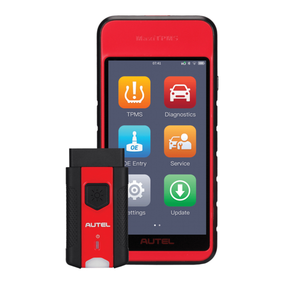
2 General Introduction When it comes to ultra-portability, MaxiTPMS ITS600 or MaxiTPMS ITS600 Pro (hereinafter referred to as ITS600/ITS600 Pro) is your perfect companion. ITS600/ITS600 Pro offers maximum convenience and swift diagnosis. The intuitive user interface makes using the device effortlessly through a 5.5-inch LCD touch screen that displays at 1280 x 720 quality. -
Page 14: Maxitpms Its600/Its600 Pro Tablet
2.1 MaxiTPMS ITS600/ITS600 Pro Tablet 2.1.1 Function Description Figure 2-1 Display Tablet Front View ① 5.5” LCD Capacitive Touchscreen ② Ambient Light Sensor – detects ambient brightness. ③ Power LED – indicates battery level & charging or system status. ④ TPMS Service Symbol – indicates the position of the embedded TPMS antenna. - Page 15 Figure 2-2 Display Tablet Back View ① Sticker ② Rear Camera ③ Camera Flash ④ Speaker Figure 2-3 Display Tablet Top View ① Micro SD Card Slot ② Type-C USB OTG Port ③ Microphone...
-
Page 16: Power Sources
2.1.2 Power Sources The tablet can receive power from any of the following sources: Internal Battery Pack ⚫ ⚫ AC/DC Power Supply ⚫ Vehicle Power Supply Internal Battery Pack The tablet can be powered with the internal rechargeable battery, which if fully charged can provide sufficient power for about 7 hours of continuous video watching and 5 hours of operations. -
Page 17: Technical Specifications
2.1.3 Technical Specifications Table 2-1 Specifications Item Description Recommended Use Indoor Android Operating System Processor Quad-core processor (1.5 GHz) Memory 2 GB RAM DDR4 & 64 GB ROM 5.5-inch LCD capacitive touchscreen with Display 1280 x 720 resolution ⚫ Wi-Fi Connectivity ⚫... -
Page 18: Vci - Vehicle Communication Interface
Item Description Storage Temp. -20 to 60°C (-4 to 140°F) 183.0 mm (7.2″) x 89.0 mm (3.5″) x 22.0 mm Dimensions ( W x H x D (0.87″) Net Weight 368 g (0.8 lb.) ISO9141-2, ISO14230-2, ISO15765, K/L- Protocols Line, Flashing Code, SAE-J1850 VPW, SAE-J1850PWM, ISO11898 (Highspeed, Middlespeed, Lowspeed and Singlewire CAN, fault-tolerant CAN), SAE J2610, GM... - Page 19 ④ Vehicle Data Connector (16-Pin) – connects the MaxiVCI V200 to the vehicle’s 16-pin DLC directly. ⑤ USB Port – provides the easiest connection between the device and the display tablet via a USB cable. Table 2-2 Power LED on the Front Panel Color Description Lights yellow at power up when VCI is self-...
-
Page 20: Technical Specifications
2.2.2 Technical Specifications Table 2-4 Technical Specifications Description Item Communications ⚫ BLE + EDR ⚫ Type-C USB Wireless Frequency 2.4 GHz Input Voltage Range 8 V to 30V DC Supply Current 150 mA @ 12 V DC Operating Temp. 0°C to 50°C (32°F to 122°F) Storage Temp. -
Page 21: Other Accessories
2.3 Other Accessories Table 2-5 Accessories Power Adapter Used with USB cable to charge ITS600/ITS600 Pro via DC electrical outlet. USB Cable Connect to power adapter and ITS600/ITS600 Pro for charging. Hex Key Used to install and uninstall the sensor. -
Page 22: Getting Started
3 Getting Started Ensure the tablet is sufficiently charged or is connected to a power outlet (see Power Sources on page 6). 3.1 Powering Up Long press the Lock/Power button on the right side of the tablet to switch the unit on. The system boots up and displays the MaxiTPMS Job Menu. Figure 3-1 Sample Job Menu of ITS600... -
Page 23: System Status Icons
Figure 3‑2 Sample Job Menu of ITS600 Pro ① System Status Icons ② Application Buttons ③ Locator Almost all operations on the tablet are controlled through the touchscreen. The touchscreen navigation is menu driven allowing for quick access to test procedure, or data that you need, through a series of questions and options. -
Page 24: Application Buttons
Table 3-1 System Status Icons Button Name Description System Launches the Android System Settings Settings interface when pressed. Enables/disables Bluetooth when Bluetooth pressed. WLAN Enables/disables Wi-Fi when pressed. Flashlight Turns on/off flashlight when pressed. Screenshot Takes a screenshot of the display. Automatic Adjusts the screen brightness to your brightness... - Page 25 Button Name Description Assesses the battery test menu. See Battery Test Battery Test on page 61 for details. Accesses OEM menu. SeeOE Entry OE Entry page 76 for details. Accesses diagnostic functions menu (the diagnostics function is available with an Diagnostics additional purchase).
-
Page 26: Locator
Button Name Description Accesses all system diagnostics and Activate service function. Activate function Function on page 152 for details. 3.1.3 Locator The locator icon displays at the bottom of the MaxiTPMS Jobs screen. Swipe the screen left or right to view the previous or next screen. 3.2 Powering Down All vehicle communications must be terminated before powering off the tablet. -
Page 27: Tpms
4 TPMS ITS600/ITS600 Pro provides an extensive series of TPMS-related services and functions. Quickly identifies vehicle information and easy to operate, ITS600/ITS600 Pro is an ideal choice for technicians to complete TPMS work. 4.1 Getting Started 4.1.1 TPMS Service Menu Layout Tap TPMS on the MaxiTPMS Job Menu to access the Vehicle Identification screen. - Page 28 This function will record the communication data and ECU information Data Logging of the test vehicle and send it to Autel's technical staff to review and provide solution. See Data Logging on page 146 for details.
-
Page 29: Vehicle Identification
⚫ Market Select the market where the user resided, featuring the Europe, North America, Korea, Japan, and Australia market. ⚫ License Select License, tap to scan license plate number or manually input the plate number. ⚫ to perform the VIN Scan method or manually input VIN code to identify your vehicle make/model/year. -
Page 30: Auto Vin Detect
4.2.1 Auto VIN Detect Auto VIN Detect function is used to quickly identify the test vehicle. Before operating, make sure a communication link is established between the test vehicle and the tablet via the MaxiVCI V200. Refer to Establish Vehicle Communication on page 31 for details. - Page 31 Figure 4-2 Sample Scan License 1...
-
Page 32: Scan Vin
Figure 4-3 Sample Scan License 2 4.2.3 Scan VIN ➢ To perform Scan VIN to perform the Scan VIN method, the camera will be opened. At the bottom of the screen, from left to right, two options are available, Barcode/QR code Scan and Scan VIN. Select one of two options and position the tablet to align the VIN code within the scanning window, the result displays in the Recognition result dialog box after scanned. -
Page 33: Manual Input
Figure 4-4 Sample Scan VIN 4.2.4 Manual Input For vehicles that do not support scanning function, the MaxiTPMS system allows you to enter the vehicle VIN or license numbers manually, or simply take a photo of the VIN sticker or license plate for quick vehicle identification. ➢... - Page 34 Figure 4-5 Sample Vehicle Model Selection Figure 4-6 Sample Vehicle Year Selection...
- Page 35 The following screen may display for vehicles using Indirect TPMS. Figure 4-7 Sample Indirect TPMS Selection Screen For Indirect TPMS vehicle, only the Relearn function is supported. Not all vehicle lines provide Indirect TPMS mode. Tap the Year option bar to open a dropdown list of model year.
- Page 36 Figure 4-8 Sample Relearn Procedure for Indirect TPMS For vehicles using Direct TPMS, select the correct vehicle. The TPMS service menu will display next. Figure 4-9 Sample TPMS Screen ① Top Toolbar Buttons – refer to Table 4-2 Top Toolbar Buttons on Service Menu on page 27 for details.
- Page 37 ③ Main Section ④ Function Buttons 4.2.4.1 Top Toolbar Buttons Table 4-2 Top Toolbar Buttons on Service Menu Button Name Description Back Returns to the previous screen. Exit Returns to the MaxiTPMS Job Menu. Includes Data Logging Report functions. ⚫ Data Logging: Records...
- Page 38 Diagnosis Tab – Communicates with the test vehicle to perform diagnostics function, and displays diagnostics results including live data, DTCs, and etc. Programming Tab – Program the MX-sensors, displays the new programmed sensor IDs and sensor PSNs (Product Serial Number). Relearn Tab –...
-
Page 39: Tpms Check
4.3 TPMS Check The Check function allows user to activate TPMS sensor to view sensor data - sensor ID, tire pressure, tire temperature, battery condition and sensor position. ➢ To check the sensors Follow the steps in Vehicle Identification on page 19 to select the test vehicle. - Page 40 Figure 4-10 Sample Check Screen The sensor position, sensor ID, tire pressure, tire temperature, sensor frequency and sensor battery information of the triggered sensor will display on the table. Table 4-3 Possible Results for Triggering Icon Results Description TPMS sensor successfully Successful activated and decoded.
-
Page 41: Tpms Diagnosis
Icon Results Description If the search period expires and no sensor is activated or decoded, the sensor may be mounted incorrectly or does not function. The table displays “Failed”. Failed Sensor If the tire pressure is not in the Read normal range, the icon will turn red. - Page 42 4.4.1.2 VCI Connection The MaxiVCI V200 Power LED will light solid green when properly connected to vehicle and ready to establish communication with the tablet. The wireless diagnostic interface MaxiVCI V200 supports two communication methods with the tablet, wireless Bluetooth and wired USB. ⚫...
-
Page 43: Diagnosis Operations
In case of Bluetooth connection, check if the network is configured ⚫ correctly, or if the right MaxiVCI V200 has been paired up with the tablet. If communication is lost during diagnosis, ensure there is no nearby object that might cause signal interruption. ... - Page 44 Figure 4-11 Sample Communication Screen Figure 4-12 Sample Diagnostics Screen 1 If the OBD function is supported by the test vehicle, the sensor ID saved in the TPMS ECU will be retrieved and displayed on the screen with an OBD icon adjacent to it.
- Page 45 If the sensor ID retrieved from sensor activation is the same as the ID saved in the ECU, the trigger mark ( ) and OBD mark ( ) will display green. If the IDs are different, the marks will display red ( ).
- Page 46 Figure 4-14 Sample No DTC Screen ⚫ Retry Diagnosis Tap Retry Diagnosis, to establish communication with ECU again and retrieve sensor IDs and the DTCs present in the ECU. ⚫ Clear DTCs Tap Clear DTCs, to clear the DTCs from the ECU. It is recommended that DTCs are read and needed repairs are performed before erasing codes.
- Page 47 Figure 4-15 Sample Live Data Screen The Live Data screen displays all real time data. ◆ on the right of screen to view details of the data stream. ◆ to open the dialogue box on the screen for additional information. Figure 4-16 Sample Details of Data Stream Screen...
- Page 48 There are three types of display modes available for data viewing, enabling you to view parameters in the mode that best suited to present data, and one Unit section, for switching the unit according to your preference. ➢ To set the display mode Select the live data item of which parameters you want to view.
-
Page 49: Sensor Programming
Figure 4-17 Sample Service Function Screen Tap the function displayed to initiate the desired service. 4.5 Sensor Programming The Programming function allows users to program the sensor data to the MX-Sensor to replace existing sensors with low battery life and ones that are no longer functioning. -
Page 50: Copy By Obd
Figure 4-18 Sample Programming Screen 4.5.1 Copy by OBD If the IDs retrieved from sensor activation and those registered to the TPMS ECU are different, use Copy by OBD to program the IDs saved in the ECU to the new MX-Sensor. By using this function, the tablet will program the sensor IDs retrieved from the ECU of the test vehicle to the new MX-Sensors. -
Page 51: Auto Create
Figure 4-19 Sample Copy by OBD Screen When the programming is complete, the programmed ID will display in the column to the left of the wheel designation. In the pictured example, the new ID is displayed to the right of the LF column. By using Copy by OBD, the sensor ID that is retrieved from TPMS ECU is programmed to the new MX-Sensor. - Page 52 Select the vehicle model, select a wheel location on the display and place MX-Sensors in front of the tablet. Tap Auto Create to program new MX- Sensors. New IDs will be created for the MX-Sensors. These new IDs differ from the IDs stored in the TPMS ECU, therefore, the sensors will have to be relearned to the TPMS ECU.
-
Page 53: Tpms Relearn
NOTE Because the new IDs were created, relearn is necessary. Figure 4-21 Sample Auto Create Diagram 4.6 TPMS Relearn This function is used to transfer new sensor IDs into the vehicle ECU for sensor recognition. Step-by-step relearn instructions are provided for all supported vehicles. -
Page 54: Obd Relearn
4.6.1 OBD Relearn 4.6.1.1 OBD Relearn The OBD Relearn function allows the ITS600/ITS600 Pro tablet to directly write the TPMS sensor IDs to the TPMS module. NOTE A few vehicle lines do not support OBD Relearn for original design. If the function is supported by the selected vehicle, the OBD Relearn button will display on the bottom of the screen. -
Page 55: Automatic Relearn
Figure 4-23 Sample OBD Relearn Screen 2 4.6.1.2 OBD-Assisted Relearn ITS600/ITS600 Pro can also perform an OBD-Assisted Relearn session directly. Some vehicles relearn procedure require that a tool be always connected to the vehicle while another tool be used to trigger the sensor at the wheel. - Page 56 Figure 4-24 Sample Automatic Relearn Screen 1 Figure 4-25 Sample Automatic Relearn Screen 2...
-
Page 57: Stationary Relearn
4.6.3 Stationary Relearn Stationary Relearn requires the vehicle be placed in the “Relearn Mode”. Tap Relearn to access the relearn menu. Figure 4-26 Sample Stationary Relearn Screen 1 Then follow the Relearn Procedure to perform Stationary Relearn. Figure 4-27 Sample Stationary Relearn Screen 2... -
Page 58: Retrofit
4.7 Retrofit Refer to TPMS Retrofit on page 59 for details. 4.8 Wear Detection The wear detection is for detecting wear status of tire tread and/or brake disc, which contains four types of checks, including All tread check, Quick check, Single check, and Brake disc check operations, and allows for adding tire tread depth &... -
Page 59: Function Operations
Figure 4-28 Sample TBE Manager Screen Prior to measuring, also make sure to adjust settings on the Wear detection screen via the tablet or through Check settings on the TBE device. 4.8.1 Function Operations To use this function, the TBE device must be connected to the tablet. Follow the instructions in the Note section to perform the wear detection function. - Page 60 Figure 4-29 Sample Wear Detection Screen 1. Check Settings ⚫ Tread check mode – Four modes are available, including All tread check, Quick check, Single check, and Brake disc check. ⚫ Tire type – displays three tire types, including Summer, Winter, and All-season tires.
- Page 61 Figure 4-30 Sample Check Settings Screen 4.8.1.1 Check Settings Check settings contains a series of settings that allow you to perform check operations as you desired, such as the check mode, tire type, limit settings, and data unit. 4.8.1.2 Main Section The Main section in the center of the screen displays the TBE icon as well as the vehicle model tested graphically.
-
Page 62: Check Mode
4.8.2 Check mode There are four check modes provided. Below are the detailed descriptions. 4.8.2.1 All tread check The All tread check function assists to examine your tire wear in three separate areas: outer, center, and inner for a comprehensive analysis. 4.8.2.2 Single check The single check function allows for measuring tread depth on each tire... - Page 63 NOTE A prompt will display when tap open the Tire Tread function, notifying the current check mode and if want to switch to another one. You can also switch between All tread check and Single check in the Check Settings via the TBE device. The measurement data on the TBE device will automatically transfer to and display on the paired tablet.
- Page 64 Figure 4-32 Sample Quick Check Screen Figure 4-33 Sample Single Check Screen...
-
Page 65: Details
Figure 4-34 Sample Brake Disc Check Screen 4.8.3 Details The Details screen shows a wide variety of tire and brake disc information. After measurements are shown on the Wear detection screen, select a wheel location, tap the corresponding tire or brake disc icon under the Details column to enter the next screen. - Page 66 ⚫ Brake disc check – displays only the brake disc wear. 2) Braking distance – displays the stopping distance for the test vehicle graphically with the corresponding tire tread depth. The braking distance varies with the type of tires changed accordingly. This section also followed by wear analysis and maintenance suggestions.
- Page 67 Figure 4-35 Sample Details Screen On the Wear detection screen, measurements and the tire/brake disc icon will display green, yellow or red indicating wear status. Refer to Table 4-2 Top Toolbar Buttons on Service Menu on page 27 for details. Tap the icon on the top right corner of the screen to access the TPMS test report generated.
- Page 68 Table 4-2 Possible Results for Measurements Tire Tread Quick Brake Results Description Check Disc Check The tire/brake disc (Gray) Untested is untested. The tire/brake disc is in good Good condition. (Green) It is suggested to A replacement is replace the recommended (Yellow) tire/brake disc.
-
Page 69: Tpms Retrofit
5 TPMS Retrofit Retrofit is needed to be performed if your vehicle is not installed with TPMS system by default. Tap on the TPMS Retrofit application button on the MaxiTPMS Job Menu to access the function. 5.1 Retrofit This function is used to install TPMS system in vehicles. Tapping the TPMS Retrofit application icon opens the vehicle identification screen. - Page 70 Figure 5-1 Sample TPMS Retrofit Screen NOTE Accesses the TPMS retrofit function either by tapping TPMS on the MaxiTPMS Job Menu or directly tap TPMS Retrofit to access. The TPMS Retrofit lists vehicles available for retrofit only. The TPMS application covers all vehicles, with which available for retrofit will display retrofit tab on the screen.
-
Page 71: Battery Test
6 Battery Test The BT506 is a battery and electrical system analysis tool that uses Adaptive Conductance, an advanced battery analysis method to produce a more accurate examination of the battery’s cold cranking ability and reserve capacity, vital to determining a battery’s true health. The BT506 enables technicians to view the health status of the vehicle's battery and electrical system. -
Page 72: Power Sources
② Status LED ③ Power LED ④ USB Port ⑤ Battery Clamp Cable Table 6-1 LED Description Color Description The tester is communicating via USB Flashing Green cable. Status LED Flashing Blue The tester is communicating via Bluetooth. Battery clamps are connected to the wrong Flashing Red battery terminals. -
Page 73: Technical Specifications
IMPORTANT Do not charge the battery when the temperature is below 0° C (32° F) or above 45° C (113° F). 6.1.2.1 Internal Battery Pack The BT506 tester can be powered with the internal rechargeable battery. AC/DC Power Supply — Using Power Adapter 6.1.2.2 The BT506 tester can be powered from an electrical outlet using the AC/DC power adapter. -
Page 74: Test Preparation
6.2 Test Preparation 6.2.1 Inspecting the Battery Before starting a test, inspect the battery for: Cracking, buckling or leaking (If you see any of these defects, replace ⚫ the battery.) ⚫ Corroded, loose or damaged cables and connections (Repair or replace as needed.) ⚫... -
Page 75: Connecting To A Battery
6.2.3 Connecting to a Battery ➢ To connect to a battery Press and hold the Lock/Power button to turn on the BT506 tester. Connect the red clamp to the positive (+) terminal and the black clamp to the negative (–) terminal of the battery. Figure 6-2 Connecting to a Battery The black clamp is installed with an infrared sensor near the clamp mouth that tests the battery temperature. -
Page 76: In-Vehicle Test
6.3 In-vehicle Test In-vehicle Test is used for testing batteries that are installed in a vehicle. An in-vehicle test includes battery test, starter test, and generator test. These tests help determine the health status of the battery, the starter, and the generator, respectively. - Page 77 Figure 6-4 Battery Test Screen Perform OBD connect by following the on-screen instructions. Figure 6-5 OBD Connect Screen...
- Page 78 Confirm the vehicle information. The vehicle information will be automatically populated when vehicle communication established. A Battery Information tab will pop up from the bottom of the screen. Figure 6-6 Sample Vehicle Information Screen Table 6-2 Upper Toolbar Buttons Name Button Description Back...
- Page 79 Figure 6-7 Sample Battery Screen Figure 6-8 Sample Battery Result Screen...
-
Page 80: Starter Test
6.3.2 Starter Test ➢ To perform the starter test Tap Continue. Perform required operations before the battery test based on the on-screen instructions. And tap the Start testing button. Figure 6-9 Sample Starter Screen 1 Turn the vehicle ignition to ON when the following screen displays. Figure 6-10 Sample Starter Screen 2... - Page 81 Wait for the test to complete and view the test results. Figure 6-11 Sample Starter Test Result Screen Table 6-3 Starter Test Results Result Description Cranking Normal Starter is good. Current Too Low Low momentary discharge capacity. Voltage Too Low Low battery storage capacity.
-
Page 82: Generator Test
6.3.3 Generator Test ➢ To perform the generator test Tap Continue. Perform required operations based on the on- screen instructions. Tap Continue and view the test results. Figure 6-12 Sample Generator Test Result Screen... - Page 83 Table 6-4 Generator Test Results Result Description Charging Normal The generator is good. ⚫ The belt linking the starter and the generator is loose; Output Too Low ⚫ The cable linking the starter and battery is loose or corroded. ⚫ The generator is not properly connected to the ground;...
-
Page 84: Out-Vehicle Test
6.4 Out-vehicle Test Out-vehicle test is used to test the condition of batteries that are not connected to a vehicle. This function aims to check the health status of the battery only. The battery types and standards able to be tested are as follows. Types: FLOODED, AGM, AGM SPIRAL, EFB, and GEL Standards: CCA, SAE, CA, EN, IEC, DIN, JIS and MCA 6.4.1 Battery Test... - Page 85 Figure 6-14 Sample Out-vehicle Test Result Screen Table 6-5 Out-vehicle Test Results Result Description Good Battery Battery meets required standards. Battery is good, but low on charge. Fully charge Good & Recharge the battery. Check for causes of low charge. Charge &...
-
Page 86: Oe Entry
7 OE Entry 7.1 TPMS by OEM Part No. If the sensor's OEM part No. is known, this function is an efficient method to activate all known TPMS sensors and program specifically the MX-Sensors. Selecting the OEM part No. opens the functional page for performing sensor activation and programming. - Page 87 name to enter the next screen and then select the specific OEM sensor Figure 7-1 Sample OEM Sensor Manufacturer Screen Or, tap All OEM-Part No., to the search box on the top of the screen to enter the OEM part No. A soft keyboard will display as below. Enter the OEM Part No.
- Page 88 When a specific OEM part No. is selected, the screen will display as pictured below. Figure 7-3 Sample OEM Part No. Service Menu NOTE Only sensor Check and Programming functions are available. The Diagnosis and Relearn functions can only be accessed by selecting a vehicle on the TPMS service menu.
- Page 89 Figure 7-4 Sample Check Screen via OEM Part No. 7.1.2.2 Programming The programming function is used to program the sensor data to the MX- Sensor and replace the faulty sensor. Tap Auto Create to program MX-Sensor using the OEM Part NO. function. Auto Create on page 41.
- Page 90 Figure 7-5 Sample Programming Screen via OEM Part No. The PSN Code (Part Serial Number), which is printed on the MX-Sensor, acts as a reference to identify the corresponding sensor ID. This can be especially useful when programming multiple MX-Sensors. 7.1.2.3 Support Support will display the correct vehicle types for the selected OEM part No.
- Page 91 Figure 7-6 Sample Support Screen...
-
Page 92: Diagnostics
8 Diagnostics The Diagnostics application, via the MaxiVCI V200, can access the electronic control module (ECM) for various vehicle control systems, such as engine, transmission, antilock brake system (ABS), airbag system (SRS), view live data parameters. The all-system diagnostics function is available with update purchase. -
Page 93: Vehicle Identification
① Top Toolbar Buttons – see Table 4-1 Top Toolbar Buttons on Vehicle Menu on page 18 for details. ② Manufacturer Buttons – To begin, select the manufacturer button of the test vehicle, followed by the vehicle model and year. 8.2 Vehicle Identification The MaxiTPMS diagnostic system supports four methods of Vehicle Identification. - Page 94 Figure 8-2 Sample Auto VIN Screen Select Auto VIN. Once the test vehicle is identified, the screen will display the vehicle identification number (VIN). Tap OK at the bottom right to confirm the VIN. If the VIN does not match with the test vehicle’s VIN, enter VIN manually or tap Read to acquire VIN again.
- Page 95 Figure 8-3 Sample VIN Information Screen Review the information. Tap YES to confirm the vehicle profile or NO to cancel. Figure 8-4 Sample Vehicle Profile Screen The tool establishes communication with the vehicle and opens the Main menu. Tap Diagnosis and select Auto scan to scan all the...
- Page 96 test vehicle available systems or tap Control unit to access a specific system to diagnose. Figure 8-5 Sample Vehicle Profile Screen...
-
Page 97: Manual Vin Input
8.2.2 Manual VIN Input For vehicles not supporting the Auto VIN Scan function, manually enter the vehicle VIN. ➢ To perform Manual VIN Input Tap the Diagnostics application button on the MaxiTPMS Job Menu. The Vehicle Menu displays. Tap the VIN Scan button on the top toolbar to open the dropdown list. -
Page 98: Automatic Selection
8.2.3 Automatic Selection The Auto Selection can be selected after selecting the test vehicle manufacturer. ➢ To perform Automatic Selection Tap the Diagnostics application button on the MaxiTPMS Job Menu. The Vehicle Menu displays. Tap the manufacturer menu of the test vehicle and then Automatic Selection. -
Page 99: Navigation
a series of on-screen prompts and selections the test vehicle is chosen. Confirm vehicle profile before starting diagnostics. 8.3 Navigation Navigating the Diagnostics interface and selecting tests is discussed in this section. 8.3.1 Diagnostics Screen Layout Figure 8-8 Sample Diagnostics Screen The diagnostic screens typically include two sections. -
Page 100: Screen Messages
8.3.1.2 Main Section The Main Section of the screen varies depending on the stage of operations. The Main Section can display vehicle identification selections, the main menu, test data, messages, instructions and other diagnostic information. 8.3.2 Screen Messages Screen messages appear when additional input is needed before proceeding. There are mainly three main types of on-screen messages: Confirmation, Warning, and Error. -
Page 101: Diagnosis
8.4 Diagnosis The Diagnostics application enables a data link to the electronic control system of the test vehicle for vehicle diagnosis or service. The application performs functional tests, retrieves vehicle diagnostic information such as trouble and event codes and live data from various vehicle control systems such as engine, transmission, ABS, and more. - Page 102 Figure 8-9 Sample Auto Scan Operation Screen ① Main Section ② Function Buttons Main Section Column 1 – displays the system numbers. Column 2 – displays the scanned systems. Column 3 – displays the diagnostic indicators describing test results. These indicators are defined as follows: -!-: ...
-
Page 103: Control Units
Function Buttons A brief description of the operations of the Auto Scan's Function Buttons' operations are displayed in the table below. Table 8-1 Function Buttons in Auto Scan Name Description Create PDF Creates PDFs for data viewing. Report Displays the diagnostic data in the report form. Deletes codes. - Page 104 Figure 8-10 Sample Function Menu Screen The Function Menu options vary slightly for different vehicles. The function menu may include: ECU Information – provides the retrieved ECU information in detail. An ⚫ information screen opens upon selection. Read Codes – displays detailed information of DTCs retrieved from the ⚫...
- Page 105 Locate the required system for testing by Auto Scan or through menu driven selections in Control Units. Select the desired diagnostic function from the Function Menu. 8.4.2.1 ECU Information This function retrieves and displays the specific information for the tested control unit, including unit type, version numbers and other specifications.
- Page 106 Figure 8-12 Sample Read Codes Screen ① Diagnostics Toolbar Buttons – see Table 4-2 Top Toolbar Buttons on Service Menu on page 27 for details. ② Main Section ⚫ Code Display area – displays the retrieved codes from the vehicle. ⚫...
- Page 107 Before performing this function, make sure the vehicle's ignition key is in the ON (RUN) position with the engine off. To erase codes ➢ Tap Erase Codes from the Function Menu. A warning message displays to advice of data loss if this function is completed.
- Page 108 Figure 8-13 Sample Live Data Screen ① Diagnostics Toolbar Buttons – see Table 4-2 Top Toolbar Buttons on Service Menu on page 27 for details. ② Main Section Name Display area – displays the names and current values of the ⚫...
- Page 109 Analog Gauge Mode – displays the parameters in the form of an analog meter graph. Text Mode – this is the default mode that displays the parameters in texts, displaying in list format. NOTE Status parameters, such as a switch reading, can primarily be viewed in test form such as ON, OFF, ACTIVE, and ABORT.
-
Page 110: Generic Obdii Operations
8.5 Generic OBDII Operations This option presents a quick way to check for DTCs, isolate the cause of an illuminated malfunction indicator lamp (MIL), check monitor status prior to emissions certification testing, verify repairs, and perform a number of other services that are emissions-related. - Page 111 Figure 8-15 Sample OBDII Diagnostic Menu NOTE Tap the button beside the function name to an information bubble with additional function information. Select a function option to continue. ⚫ DTC & FFD I/M Readiness ⚫ ⚫ Live Data ⚫ O2 Sensor Monitor On-Board Monitor ⚫...
-
Page 112: Function Descriptions
8.5.2 Function Descriptions This section describes the various functions of each diagnostic option. 8.5.2.1 DTC & FFD When this function is selected, the screen displays a list of Stored and Pending Codes. A snowflake button will display on the right side of the DTC item if the Freeze Frame data is available for viewing. - Page 113 technician after a vehicle repair and after clearing diagnostic information by reporting test results after a driving cycle. If a test failed during the drive cycle, the DTC associated with that test is reported. If the pending fault does not occur again within 40 to 80 warm-up cycles, the fault is automatically cleared from memory.
- Page 114 8.5.2.3 Live Data This function displays the real time PID data from ECU. Displayed data includes analog inputs and outputs, digital inputs and outputs, and system status information broadcast on the vehicle data stream. Live data can be displayed in various modes, see Live Data on page 97 for detailed information.
-
Page 115: Exiting Diagnostics
8.6 Exiting Diagnostics The Diagnostics application remains open as long as there is an active communication with the vehicle. Exit the diagnostics operation interface to stop all communications with the vehicle before closing the Diagnostics application. NOTE Damage to the vehicle electronic control module (ECM) may occur if communication is disrupted. -
Page 116: Service
9 Service The Service section is specially designed to provide quick access to the vehicle systems for various scheduled service and maintenance tasks. The typical service operation screen is a series of menu driven executive commands. Follow the on-screen instructions to select appropriate execution options, enter correct values or data, and perform necessary actions. - Page 117 emission inspection and vehicle checks. ➢ To perform oil reset functions Tap the Service application button on the MaxiTPMS Job Menu. Tap Oil Reset button. The vehicle manufacturer screen displays. Tap VIN Scan or the vehicle make to acquire vehicle VIN information and tap Yes to confirm vehicle profile.
- Page 118 Figure 9-2 Sample Oil Reset Service Screen 1 The available items will display in a table of three columns: CBS value, availability, and service counter. Figure 9-3 Sample Oil Reset Service Screen 2 Tap on the value to reset and then tap the Reset button at the bottom left of the screen.
-
Page 119: Electric Parking Brake (Epb) Service
Figure 9-4 Sample Oil Reset Service Screen 3 When the reset is done, the availability will display as 100%. Tap ESC to exit. 9.2 Electric Parking Brake (EPB) Service This function has a multitude of usages to maintain the electronic braking system safely and effectively. - Page 120 Ensure that the EPB control system is reactivated after the maintenance work has been completed. NOTE Autel accepts no responsibility for any accident or injury arising from the maintenance of the Electric Parking Brake system. ➢ To perform EPB functions Tap the Service application button on the MaxiTPMS Job Menu.
-
Page 121: Emf Start-Up
9.2.2 EMF Start-up This service function would start the parking brake. It must be conducted after the following repairs: Replacing an EMF control unit ⚫ ⚫ Replacing the parking brake button Figure 9-6 Sample EMF Star-up Screen 1 To perform EMF Start-up ➢... - Page 122 Figure 9-7 Sample EMF Star-up Screen 1 The following screen will display a message to advice that the fault memory of the parking brake control unit will be deleted, tap Continue to proceed, or tap Back to exit. Figure 9-8 Sample EMF Star-up Screen 3 Follow the on-screen instructions to pull the parking brake button.
-
Page 123: Parking Brake: Workshop Mode
When the operation is successfully completed, a “Completed successfully” message will display on the screen, press OK to exit. 9.2.3 Parking Brake: Workshop Mode This service is used to activate and deactivate the installation position for the Automatic Hold brake. In this mode the parking brake is moved into the opened position and temporarily deactivated (personal protection). -
Page 124: Battery Management System (Bms) Service
9.3 Battery Management System (BMS) Service The Battery Management System (BMS) allows the scan tool to evaluate the battery charge state, monitor the close-circuit current, register the battery replacement, activate the rest state of the vehicle, and charge the battery via the diagnostic socket. - Page 125 Tap the Service application button on the MaxiTPMS Job Menu. Tap the BMS button. The vehicle manufacturer selection screen displays. Tap VIN Scan or the vehicle manufacturer to acquire vehicle VIN information and tap Yes to confirm. See Vehicle Identification on page 83 for details.
- Page 126 Figure 9-10 Sample BMS Screen 1 Read carefully the complete information and follow the steps. Figure 9-11 Sample BMS Screen 2 Check the battery capacity and the battery replacement information on the screen. Tap function 1 (F1) to return to the selection screen.
- Page 127 Figure 9-12 Sample BMS Screen 3 ➢ To register the battery replacement Tap on the appropriate step to complete. In our example, tap function 1 (F1) Register battery replacement. Figure 9-13 Sample BMS Screen 4 Read carefully the information on the screen. Scroll through lists to view all the functions.
- Page 128 Figure 9-14 Sample BMS Screen 5 Enter battery replacement: same capacity Enter battery replacement: different capacity Enter battery replacement: Changing from the normal lead- acid battery (white housing) to AGM battery (black housing) Figure 9-15 Sample BMS Screen 6 Read carefully the information on the screen and tap Yes to continue. Follow the on-screen instructions to input the data matrix code of the newly installed battery that should be on the label of the battery.
-
Page 129: Steering Angle Sensor (Sas) Service
Figure 9-16 Sample BMS Screen 7 When the battery exchange is successfully entered, tap Continue to exit. Figure 9-17 Sample BMS Screen 8 9.4 Steering Angle Sensor (SAS) Service Steering Angle Sensor Calibration permanently stores the current steering wheel position as the straight-ahead position in the steering angle sensor EEPROM. - Page 130 NOTE Autel accepts no responsibility for any accident or injury arising from servicing the SAS system. When interpreting DTCs retrieved from the vehicle, always follow the manufacturer’s recommendation for repair.
-
Page 131: Steering Angle Sensor Calibration
Figure 9-18 Sample SAS Function Menu 9.4.1 Steering Angle Sensor Calibration This function allows users to perform steering angle sensor calibration, clear records and clear counter. The function options vary by vehicle. ➢ To perform the SAS calibration Tap Steering Angle Sensor Calibration from the SAS function menu to enter the function screen. - Page 132 Figure 9-19 Sample SAS Function Screen 1 When the operation is finished, the scan tool will display a confirmation message. An error message will display if the procedure cannot be completed. Exit the diagnosis program, and solve the error before attempting SAS calibration again. Figure 9-20 Sample SAS Function Screen 2 NOTE For ITS600 Pro, TPMS software offers free-of-charge updates and they...
- Page 133 be updated to ITS600 Pro with an additional purchase of all system diagnosis and other service function software.
-
Page 134: Tire Dot
10 Tire DOT The Tire DOT application contains the following parts – Tire Registration, Tire Recall Lookup and Tire Age Check functions. Figure 10-1 Sample Tire DOT Screen ⚫ Tire Registration – Allows you to register E-tires by following on-screen instructions. - Page 135 Figure 10-2 Tire Registration Screen ⚫ Tire Recall Lookup – Detects tire status of the test vehicle. When the DOT number on a tire is scanned or automatically entered, the information of tire age, warning, and recall status will display on the screen.
- Page 136 ⚫ Tire Age Check – Displays tire status of the test vehicle. When the DOT number on a tire is scanned or automatically entered, the information of tire age and warning will display on the screen. Figure 10-4 Tire Age Check Screen NOTE The Tire Registration and Tire Recall Lookup functions are only supported in North American region.
-
Page 137: Settings
11 Settings Tap the Settings button to adjust the default settings and view information about the MaxiTPMS system: ⚫ TPMS Market ⚫ TPMS Prog. Setting ⚫ TBE Manager ⚫ VCI Manager ⚫ System Settings ⚫ Printer Manager ⚫ Report Upload to Cloud Unit ⚫... -
Page 138: Vci Manager
➢ To connect the TBE device with the tablet via Wi-Fi direct mode On the TBE device, tap Settings > Network connection. Connect to Wi-Fi first and swipe the Wi-Fi direct toggle to turn the Wi-Fi direct mode on. On the tablet, tap Settings > TBE Manager to access the TBE Manager screen. -
Page 139: Bluetooth Connection
Connection Mode – there are two connection modes available for selection. The connection state displays. Bluetooth – when paired to a wireless device, the connection state ⚫ displays as “Paired”, otherwise, it displays as “Unpaired”. Firmware upgrade – updates the V200 with the latest version of ⚫... -
Page 140: Update Via Usb
V200 illuminates solid green. This signifies that the tablet is connected to the MaxiVCI V200, and is ready to perform vehicle diagnosis. Tap the paired device again to unpair it. Tap the Home icon on the top left to return to the MaxiTPMS Job Menu. -
Page 141: Report Upload To Cloud
11.7 Report Upload to Cloud Toggle the ON/OFF button to enable or disable the Report Upload to Cloud function. If the button displays blue, it indicates the function is enabled. If the button displays gray, it indicates the function is disabled. 11.8 Unit This option allows you to adjust the measurement unit for the diagnostic system. -
Page 142: About
11.9 About About displays information regarding the ITS600/ITS600 Pro tablet, including the password, system version, hardware version, and the device's serial number. ➢ To check the MaxiTPMS product information in About Tap the Settings application on the MaxiTPMS Job Menu. Tap About to open the product information screen. -
Page 143: Toolkit
12 ToolKit This chapter describes auxiliary functions for TPMS service and vehicle diagnosis. Figure 12-1 Sample ToolKit Screen ⚫ RKE & RF – This function is used to check the signal strength of 315 and 433 MHz frequencies of remote keyless entry Fobs. ⚫... -
Page 144: Update
13 Update This chapter describes the update operation for the ITS600/ITS600 Pro tablet. The software updates can be completed on the tablet via the Internet. 13.1 Display Tablet Update The Update function application allows you to download the latest released software. - Page 145 ① Navigation and Controls ⚫ Return Button – returns to the MaxiTPMS Job Menu. ⚫ Update All – downloads all available updates. Search Bar – searches specific update item by inputting the file ⚫ name. Example: enter a vehicle manufacturer. ②...
-
Page 146: Maxivci V200 Update
13.2 MaxiVCI V200 Update Before updating the V200 software, ensure the tablet's network connection to the Internet is stable. The V200 supports Bluetooth and USB communications. 13.2.1 Update via Bluetooth ➢ To update the MaxiVCI V200 firmware via Bluetooth Connect the V200 to the vehicle or charge it with an adapter before pairing it with the tablet via Bluetooth. -
Page 147: Data Manager
14 Data Manager The Data Manager application allows you to store, pint, and review saved files, manage workshop information and keep test vehicle history records. Selecting the Data Manager application opens the menu page which contains seven main functions: ⚫ Test records ⚫... -
Page 148: Test Records
14.1 Test Records This function stores test vehicle history records, in terms of TPMS, TPMS retrofit, Service, and Diagnostics-related information from previous diagnostics and TPMS sessions. All information is displayed in summarized details. Tap on a record to resume a diagnostic or TPMS session on a "stored vehicle". -
Page 149: Tpms Test Report
NOTE The vehicle VIN number, or license and the customer information account are correlated by default. Table 14-2 Function Buttons on the Test Records Screen Button Name Description Displays previous diagnostics Diagnostics session. TPMS Displays the previous TPMS session. Displays the previous TPMS retrofit TPMS retrofit session. - Page 150 To install the PC Link driver program Download the Maxi PC Suite from www.autel.com > Support > Downloads > Diagnostic Tool > Autel Update Tools, and install to your PC. Double click the Setup.exe. Select the installation language and the wizard will load momentarily.
-
Page 151: Workshop Information
➢ To print a report via PC Link Run the PC Link program on your computer. Select the MaxiSys Printer tab. Tap the Print icon on the tablet. A report will be sent to the computer. If the Auto Print option in the MaxiSys Printer is selected, the ⚫... - Page 152 diagnostic reports and other associated test file, will display as the header of the printed documents. Figure 14-3 Sample Workshop Information Sheet ➢ To edit the Workshop Information sheet Tap the Data Manager application on the MaxiTPMS Job Menu. Select Workshop Information. Tap each field to input the appropriate information.
-
Page 153: Image
14.3 Image The Image section contains all captured screenshot images and images taken by the high-resolution camera of 8 megapixel. Figure 14-4 Sample Image Screen ① Toolbar Buttons – used to delete the image files and go back to the previous screen. - Page 154 Button Name Description Quickly locates the image file by Search entering the vehicle name, test path, file name or file info. Tap this button to delete the Delete selected image. Tap this button to display image Details details. Tap this button to send the selected Send email image via email.
-
Page 155: Pdf
14.4 PDF The PDF section stores and displays all PDF files of the saved data. Select a PDF from the database to display. The standard Adobe Reader application is used for file viewing and editing, please refer to the associated Adobe Reader manual for detailed instructions. 14.5 Report Test reports can be viewed, saved, printed, and shared in multiple applications such as TPMS, Diagnostics, and Battery Test. -
Page 156: Data Logging
14.7 Data Logging The Data Logging section keeps records of all Feedback (submitted), Not Feedback (but saved) or History (up to the latest 20 test records) data loggings on the diagnostic system. The support personnel will receive and process the submitted reports through the Support platform. The solution will be sent back as soon as possible. - Page 157 Figure 14-6 Sample Data Logging Screen 2 ➢ To send message to the technical center Take Data logging of the TPMS function as an example, on the main TPMS screen, after the TPMS session is done, tap on the upper right corner to make a selection of error types. Tap OK to open the Details screen.
-
Page 158: Academy
15 Academy The Academy provides access to various onboard instructional videos and manuals produced by top-notch technicians and product experts, covering information on main functions such as TPMS Relearn and Rewrite functions. Please access the videos or articles saved on the tablet by tapping the images with hyperlinks displayed under this application. -
Page 159: Remote Desktop
The Remote Desktop application launches the TeamViewer Quick Support program, a simple, fast, and secure remote control interface. Use this application to receive ad-hoc remote support from Autel’s support technicians by allowing them to control the tablet on their PC via the TeamViewer... -
Page 160: Maxitools
Panel (by tapping the Logger button). 17.2 Quick Link The Quick Link application provides access to Autel's official websites and to other popular automotive service websites. These sites are invaluable resources of automotive information and repair data, which include forums,... -
Page 161: Email
Figure 17-1 Sample Quick Link Screen ➢ To open a quick link Tap MaxiTools > Quick link from the MaxiTPMS Job Menu. The Quick Link screen displays. Select a website thumbnail on the main section. The Chrome browser is launched and the selected website is opened. 17.3 Email The Email application enables sending and receiving emails after account registration. -
Page 162: Activate Pro Function
18 Activate Pro Function Activate Pro function provides a quick access to upgrade the basic version of ITS600/ITS600 Pro with an additional purchase. After the advanced version of ITS600/ITS600 Pro is downloaded, you can perform diagnosis and service functions for all vehicle brands and systems. -
Page 163: Maintenance And Service
19 Maintenance and Service 19.1 Maintenance Instructions The following shows how to maintain your devices, together with precautions to take. ⚫ Use a soft cloth and alcohol or a mild window cleaner to clean the tablet’s touchscreen. ⚫ Do not use any abrasive cleansers, detergent, or automotive chemicals on the tablet. -
Page 164: Troubleshooting Checklist
Your device may have not been properly connected to the charger. ⚫ Check the connector. NOTE If your problems persist, please contact Autel’s technical support or your local distributor. 19.3 About Battery Usage Your tablet is powered by a built-in Lithium-ion Polymer battery. The Lithium- ion Polymer battery can recharge while some charge remains without reducing your tablet’s autonomy due to the “battery memory effect”... -
Page 165: Service Procedures
DANGER The built-in Lithium-ion Polymer battery is factory replaceable only; incorrect replacement or tampering with the battery pack may cause an explosion. Do not use a damaged battery charger. ⚫ Do not disassemble or open crush, bend or deform, puncture or shred. ⚫... -
Page 166: Technical Support
19.4.1 Technical Support If you have any question or problem about the operation of the product, please contact us (see the following contact info) or your local distributor. Autel China Headquarters ⚫ Phone: +86 (0755) 8614-7779 (Monday-Friday, 9AM-6PM Beijing Time) ⚫... -
Page 167: Repair Service
Email: ⚫ Address: 906-17, Preatoni Tower (Cluster L), Jumeirah Lakes Tower, DMCC, Dubai, UAE ⚫ Web: www.autel.com Autel Latin America Mexico: ⚫ Phone: +52 33 1001 7880 (Spanish in Mexico) ⚫ Email: latsupport@autel.com ⚫ Address: Avenida Americas 1905, 6B, Colonia Aldrete, Guadalajara,... -
Page 168: Other Services
Floor 2, Caihong Keji Building, 36 Hi-tech North Six Road, Songpingshan Community, Xili Sub-district, Nanshan District, Shenzhen City, China 19.4.3 Other Services You can purchase the optional accessories directly from Autel’s authorized tool suppliers, and/or your local distributor or agent. Your purchase order should include the following information: ⚫... -
Page 169: Compliance Information
20 Compliance Information 20.1 FCC COMPLIANCE FCC ID: WQ8TPMS609T This device complies with Part 15 of the FCC rules and Industry Canada’s license-exempt RSSs. Operation is subject to the following two conditions: This device may not cause harmful interference. This device must accept any interference received, including interference that may cause undesired operation. -
Page 170: Sar
– Consult the dealer or an experienced radio/TV technician for help. Changes or modifications not expressly approved by the party responsible for compliance could void the user’s authority to operate the equipment. 20.2 SAR The radiated output power of this device is below the FCC radio frequency exposure limits. - Page 171 EMC Directive 2014/30/EU R&TTE Directive 1999/5/EC Low Voltage Directive 2014/35/EU 20.6 KC COMPLIANCE R-C-WQ2-ITS600...
- Page 172 21 Warranty Limited One Year Warranty Autel Intelligent Technology Corp., Ltd. (the Company) warrants to the original retail purchaser of this MaxiTPMS Diagnostic Device that should this product or any part thereof during normal usage and under normal conditions be proven defective in material or workmanship that results in product failure...
- Page 173 leakage, blown fuse, theft or improper usage of any electrical source. IMPORTANT All contents of the product may be deleted during the process of repair. You should create a back-up copy of any contents of your product before delivering the product for warranty service.
Need help?
Do you have a question about the MAXITPMS ITS600PRO and is the answer not in the manual?
Questions and answers