Table of Contents
Advertisement
Quick Links
Trademarks
®
Autel
,
MaxiSys
®
MaxiCheck
are trademarks of Autel Intelligent Technology Corp., Ltd., registered in
China, the United States, and other countries. All other marks are trademarks or
registered trademarks of their respective holders.
Copyright Information
No part of this manual may be reproduced, stored in a retrieval system or transmitted in
any form or by any means electronic, mechanical, photocopying, recording, or
otherwise without the prior written permission of Autel.
Disclaimer of Warranties and Limitation of Liabilities
All information, specifications and illustrations in this manual are based on the latest
information available at the time of printing.
Autel reserves the right to make changes at any time without notice. While information
of this manual has been carefully checked for accuracy, no guarantee is given for the
completeness and correctness of the contents, including but not limited to the product
specifications, functions, and illustrations.
Autel will not be liable for any direct, special, incidental, or indirect damages, or for any
economic consequential damages (including the loss of profits) as a result of using this
product.
IMPORTANT
Before operating or maintaining this unit, please read this manual carefully, paying
extra attention to the safety warnings and precautions.
For Services and Support
pro.autel.com
www.autel.com
1-855-288-3587/1-855-AUTELUS (North America)
0086-755-86147779 (China)
support@autel.com
For technical assistance in all other markets, please contact your local Autel selling
agent.
®
®
,
MaxiDAS
,
®
MaxiPRO
,
MaxiRecorder
i
®
®
,
MaxiCOM
,
and
Advertisement
Table of Contents

Related Manuals for Autel MaxiDAS DS900BT


Summary of Contents for Autel MaxiDAS DS900BT
- Page 1 Autel will not be liable for any direct, special, incidental, or indirect damages, or for any economic consequential damages (including the loss of profits) as a result of using this product.
- Page 2 The safety messages herein cover situations Autel is aware of at the time of publication. Autel cannot know, evaluate or advise you as to all of the possible hazards. You must be certain that any condition or service procedure encountered does not jeopardize...
- Page 3 DANGER When an engine is operating, keep the service area WELL VENTILATED or attach a building exhaust removal system to the engine exhaust system. Engines produce carbon monoxide, an odorless, poisonous gas that causes slower reaction time and can lead to serious personal injury or loss of life. SAFETY WARNINGS ...
-
Page 4: Table Of Contents
CONTENTS 1 USING THIS MANUAL ..................... 1 ..................... 1 ONVENTIONS 1.1.1 Bold Text ...................... 1 1.1.2 Notes and Important Messages ..............1 1.1.3 Hyperlinks ..................... 1 1.1.4 Illustrations ....................2 1.1.5 Procedures ....................2 2 GENERAL INTRODUCTION .................... 3 DAS DS900-BT T ................ - Page 5 ..................20 EHICLE DENTIFICATION 4.3.1 Auto Detect ....................20 4.3.2 Manual Input ....................22 4.3.3 Scan VIN/License ..................23 4.3.4 Automatic Selection ..................25 4.3.5 Manual Selection ..................26 ....................... 26 AVIGATION 4.4.1 Diagnostic Screen Layout ................26 4.4.2 Screen Messages ..................29 4.4.3 Making Selections ..................
- Page 6 (DPF) S ............57 IESEL ARTICLE ILTER ERVICE (IMMO) S ................58 MMOBILIZER ERVICE 6 DATA MANAGER ......................60 ....................61 EHICLE ISTORY 6.1.1 Historical Test Record ................62 ................... 64 ORKSHOP NFORMATION ......................64 USTOMER ....................... 65 MAGE ......................67 EPORT PDF F ......................
- Page 7 12.6 FAQ ......................... 96 13 OEM AUTHORIZATION ....................97 14 REMOTE DESKTOP ..................... 98 15 MAXIVIDEO ........................ 100 16 QUICK LINK ....................... 101 17 AUTEL USER CENTER ....................102 18 MAINTENANCE AND SERVICE................. 103 18.1 ................103 AINTENANCE NSTRUCTIONS 18.2 .................
- Page 8 18.4.1 Technical Support ..................105 18.4.2 Repair Service ..................107 18.4.3 Other Services ..................107 19 COMPLIANCE INFORMATION .................. 108 20 WARRANTY ....................... 110 viii...
-
Page 9: Using This Manual
Using This Manual This manual contains device usage instructions. Some illustrations shown in this manual may make reference to modules and optional equipment that are not included in your system. Contact your sales representative for availability of other modules and optional tools or accessories. 1.1 Conventions The following conventions are used: 1.1.1 Bold Text... -
Page 10: Illustrations
1.1.4 Illustrations Illustrations used in this manual are samples; the actual testing screen may vary for each vehicle being tested. Observe the menu titles and on-screen instructions to make correct option selection. 1.1.5 Procedures An arrow icon indicates a procedure. Example: ... -
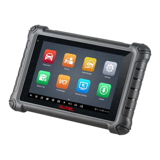
Page 11: General Introduction
General Introduction Featuring the powerful quad-core processor, and an 8.0-inch LCD capacitive touchscreen, based on the Android multitasking operating system, and combined with the ability to quickly read and clear DTCs for all available modules of the majority of the makes and models on the market, the MaxiDAS DS900-BT is your ideal auto diagnostics and service tool, providing you with superior functions, including Oil Reset, EPB (Electronic Parking Brake), SAS (Steering Angle Sensor), BMS (Battery... - Page 12 8.0” LCD Touchscreen Ambient Light Sensor — detects ambient brightness. Power LED — indicates battery level & charging or system status. The power LED displays green, yellow or red depending on power level and operating state. A. Green Illuminates green when the tablet is charging and the battery level is above 90%.
-
Page 13: Power Sources
Rear Camera Camera Flash Figure 2-3 Tablet Top View USB Type-C Charging Port Mini SD Card Slot USB Port 10. Power/Lock Button — turns the device on/off with long press, or locks the screen with short press. 2.1.2 Power Sources The tablet can receive power from any of the following sources: ... -
Page 14: Technical Specifications
2.1.3 Technical Specifications Table 2-1 Specifications Item Description Recommended Use Indoor Operating System Android Processor RK3566 Quad-core Arm Cortex-A55 processor (1.8 GHz) Memory 4 GB RAM & 64 GB ROM Display 8-inch LCD screen with 1280 x 800 resolution Rear Camera 8 MP ... -
Page 15: Maxivci V150
Item Description 168.9 mm (6.6”) x 259.8 mm (10.2”) x 33.6 mm (1.3”) Dimensions (H x W x D) Net Weight 925 g (2.04 lbs.) ISO9141-2, ISO14230-2, ISO15765, K/L-Line, Flashing Code, SAE-J1850 VPW, SAE-J1850PWM, ISO11898 (High-speed, Middle-speed, Low-speed and Single-wire Protocols CAN, fault-tolerant CAN), SAE J2610, GM UART, UART Echo Byte Protocol, Honda Diag-H Protocol, TP2.0,... -
Page 16: Power Source
Table 2-2 Power/Connection LED Color Description Lights solid green when powered on. Green Lights solid blue when the device is successfully connected via Bluetooth but is not communicating with Blue the vehicle. Flashes solid blue when the device is successfully Flashing connected via Bluetooth and is communicating with the Blue... -
Page 17: Other Accessories
Item Description Dimensions 77.47 mm x 46.8 mm x 21.38 mm (3.05’’ x 1.84’’ x 0.84’’) (H x W x D) Weight 51.5 g (0.11 lbs.) 2.3 Other Accessories USB Type-C Cable (for charging) External Power Adapter Together with the USB Type-C cable, connects the tablet to the external DC power port for power supply. -
Page 18: Getting Started
Getting Started Ensure the tablet is sufficiently charged or is connected to an external power supply (see Power Sources on page 5). NOTE The images and illustrations depicted in this manual may differ slightly from those in the most recent product. 3.1 Powering Up Long press the Power/Lock button on the top-right side of the tablet to power on the unit. -
Page 19: Application Buttons
NOTE The tablet screen is locked by default when first powered on. We recommend you lock the screen to protect the information in the system and conserve the power. The touchscreen navigation is menu-driven, enabling quick access to functions and features by tapping on the buttons on the screen. - Page 20 MaxiViewer vehicles of Autel diagnostic tools. See MaxiViewer page 92 for details. Launches the Support platform which synchronizes Autel’s on-line service base station with the MaxiDAS Support tablet. See Support on page 94 for details. Unlocks the gateway ECU (CGW) for some vehicles to...
-
Page 21: Locator And Navigation Buttons
3.1.2 Locator and Navigation Buttons Operations of the navigation buttons at the bottom of the screen are described in the table below: Table 3-2 Locator and Navigation Buttons Button Name Description Indicates which screen you are on. Swipe the screen left or Locator right to view the previous or next screen. -
Page 22: System Status Icons
Button Name Description Opens the VCI Manager application. The “BT” badge at the bottom-right corner indicates the tablet is communicating with the VCI device. An “X” badge will display at the Manager Shortcut bottom-right corner if the tablet is not connected to the VCI device. -
Page 23: Powering Down
3.2 Powering Down All vehicle communications must be terminated before shutting down the tablet. A warning message appears if you attempt to shut down the tablet while it is communicating with the vehicle. Forcing a shut-down while communicating may lead to ECU problems on some vehicles. -
Page 24: Diagnostics
Diagnostics The Diagnostics application can retrieve ECU information, read & erase DTCs, and view live data. The Diagnostics application can access the electronic control unit (ECU) for various vehicle control systems, including engine, transmission, antilock brake system (ABS), and airbag system (SRS). 4.1 Establishing Vehicle Communication Prior to performing the Diagnostics function, ensure the tablet is connected to the test vehicle through the MaxiVCI V150. -
Page 25: No Communication Message
time and providing higher efficiency. The working range for Bluetooth communication is about 33 feet (about 10 m), enabling remote vehicle diagnostics. Refer to VCI Bluetooth Pairing on page 78 for details. 4.1.3 No Communication Message A. If the tablet is not connected to the MaxiVCI V150 correctly, an “Error” message may display. -
Page 26: Getting Started
4.2 Getting Started Ensure a communication link is established between the test vehicle and the tablet via the MaxiVCI V150. 4.2.1 Vehicle Menu Layout When the tablet is properly connected to the vehicle, the platform is ready to start vehicle diagnosis. Tap the Diagnostics application button on the MaxiDAS Job Menu to access the Vehicle Menu. - Page 27 Table 4-1 Top Toolbar Buttons Button Name Description Home Returns to the MaxiDAS Job Menu. Provides a fast way to identify the test vehicle. Vehicle Identification on page 20 for details. Displays all the vehicle manufacturers. Adds your preferred vehicle manufacturers into Favorites favorites.
-
Page 28: Vehicle Identification
4.3 Vehicle Identification The MaxiDAS diagnostics system supports five methods for vehicle identification: Auto Detect Manual Input Scan VIN/License Automatic Selection Manual Selection 4.3.1 Auto Detect The MaxiDAS diagnostics system features the latest VIN-based Auto Detect function to identify vehicles and scan all the diagnosable ECUs and run diagnostics on the selected system. - Page 29 Figure 4-3 Auto Detect Screen Tap Yes to confirm the vehicle profile, or tap No if the information is incorrect. Figure 4-4 Vehicle Profile Screen The tool establishes communication with the vehicle and reads the control unit information. Choose Auto Scan to scan all the test vehicles’ available systems or tap Control Unit to access a specific system to diagnose.
-
Page 30: Manual Input
Figure 4-5 Diagnostic Menu Screen 4.3.2 Manual Input For vehicles not supporting the Auto Detect function, you may manually enter the VIN. To perform Manual Input Tap the Diagnostics application button from the MaxiDAS Job Menu. The Vehicle Menu displays. Tap the VID button on the top toolbar to open the dropdown list. -
Page 31: Scan Vin/License
Figure 4-6 Manual Input Screen Tap OK. Once the vehicle is identified, the Vehicle Diagnostics screen displays. at the top-right of the dialog box to exit Manual Input. 4.3.3 Scan VIN/License MaxiDAS diagnostic tablet also supports Scan VIN/License function. Enabling this function will automatically turn on the camera. - Page 32 Figure 4-7 Scan VIN/License 1 Select one of the three options and position the tablet to align the VIN, or license number, or the barcode within the scanning window. The scan result will display in the dialog box of the Recognition Result screen. Tap OK to confirm the result, and then the vehicle information confirmation screen will display on the tablet.
-
Page 33: Automatic Selection
Figure 4-9 Enter VIN Screen 4.3.4 Automatic Selection The vehicle VIN can also be automatically acquired after a vehicle manufacturer is selected. Figure 4-10 Selection Screen To perform Automatic Selection Tap the Diagnostics application button from the MaxiDAS Job Menu. The Vehicle Menu displays. -
Page 34: Manual Selection
Tap Automatic Selection and the VIN information will be acquired automatically. Follow the on-screen instructions to complete the operation and advance to the Diagnostic Menu screen. 4.3.5 Manual Selection When the VIN is not automatically retrievable through the vehicle's ECU, or when the VIN is unknown, you can select the vehicle manually. - Page 35 60 for details. Records the communication data and information of the test vehicle. When encountering Data an error during testing and diagnosing, use this Logging function to contact Autel's technical staff for solutions. See Data Logging on page 95 for details.
- Page 36 To print data in Diagnostics Tap the Diagnostics application button from the MaxiDAS Job Menu. The Print button on the Diagnostic Toolbar is available throughout the whole Diagnostics operations. Tap Print. A drop-down menu will be displayed: Print This Page — prints a screenshot of the current screen. ...
-
Page 37: Screen Messages
4.4.2 Screen Messages Screen messages will appear when additional input is needed before proceeding. There are three main types of on-screen messages: Confirmation, Warning, and Error. 4.4.2.1 Confirmation Messages Confirmation messages inform you when you are about to perform an action that cannot be reversed or when an action has been initiated and confirmation is needed to continue. -
Page 38: Auto Scan
4.5.1 Auto Scan The Auto Scan function performs a comprehensive scanning over all the ECUs in the vehicle to locate systems faults and retrieve DTCs. An example of Auto Scan interface is pictured as below: Figure 4-12 Auto Scan Screen Navigation Bar Main Section Function Buttons... -
Page 39: Control Unit
indicates the number of the detected faults. Pass | No Fault: Indicates the system has passed the scanning process and no fault has been detected. Column 4 — tap to enter the related system to view the detailed information and perform further diagnosis or testing. -
Page 40: Diagnostic Functions
4.6 Diagnostic Functions Figure 4-13 Function Menu Screen The Diagnostic Functions are listed on the Function Menu screen. The Function Menu options vary slightly for different vehicles, which may include: ECU Information — provides the retrieved ECU information in detail. An ... -
Page 41: Ecu Information
4.6.1 ECU Information This function retrieves and displays the specific information for the tested control unit, including unit type, version numbers, and other specifications. Figure 4-14 ECU Information Screen Diagnostics Toolbar Buttons — see Table 4-2 Diagnostics Toolbar Buttons on page 27 for detailed descriptions of the operations for each button. - Page 42 Figure 4-15 Trouble Codes Screen Diagnostics Toolbar Buttons — see Table 4-2 Diagnostics Toolbar Buttons on page 27 for detailed descriptions of the operations for each button. Main Section Column 1 — displays the retrieved codes from the vehicle. Column 2 —...
-
Page 43: Live Data
To erase codes Tap Erase Codes from the Trouble Codes screen. A warning message displays to inform you of data clearing when this function is applied. Tap Yes to continue. A Confirmation screen displays when the operation is successfully done. ... - Page 44 Main Section Name Column — displays the parameter names. Check Box — tap the check box on the left side of the parameter name to make item selection. Tap the check box again to deselect the item. Drop-down Button — tap the drop-down button on the right side of the parameter name to open a sub menu, providing data display mode options.
- Page 45 NOTE Status parameters, such as a switch reading like ON, OFF, ACTIVE, and ABORT, can only be displayed in Text Mode. Value parameters, such as a sensor reading, can be displayed in both text and graph modes. Waveform Graph Mode — displays the parameters in waveform graphs. In this mode, five control buttons will display on the right side of the parameter item, allowing you to manipulate the display status.
- Page 46 three scales available for the Y axis: x1, x2, and x4. Edit Button — tap to open an edit window, in which you can set the waveform color and line thickness displayed for the selected parameter. Zoom-out Button — tap to exit full screen display. ...
- Page 47 Figure 4-20 Trigger Settings Screen Two buttons and two input boxes are available in the Trigger Settings screen. Trigger — switches the trigger on or off. The trigger is ON by default. Buzzer Alarm — switches the alarm on or off. The alarm function makes a beeping sound as an alert when the data reading reaches the preset minimum or maximum point.
- Page 48 C. Function Buttons The operations of the available Function Buttons on the Live Data screen are described below: Cancel All — tap this button to cancel all selected parameters. Up to 50 parameters can be selected at one time. Show Selected/Show All — tap this button to switch between the two options: one displays the selected parameters, the other displays all the available items.
- Page 49 and save the setting, and return to the Live Data screen, or tap Cancel to exit without saving. Clear Data — tap this button to clear all cached live data. Freeze — displays the retrieved data in freeze mode. Previous Frame — moves to the previous frame of frozen data. ...
-
Page 50: Active Test
4.6.4 Active Test The Active Test function is used to access vehicle-specific subsystem and component tests. Available tests vary by vehicle. During an active test, the tablet sends commands to the ECU to activate the actuators. This test determines the integrity of the system or part by reading ECU data, or by monitoring the operation of the actuators. - Page 51 Figure 4-22 Special Function Screen 1 Select a function to display detailed information and the execution screen. Figure 4-23 Special Function Screen 2 List Tab Page: Column 1 — displays the description of the function being performed or the live data corresponding to the special function.
-
Page 52: Generic Obdii Operations
4.7 Generic OBDII Operations This option presents a quick way to check for DTCs, isolate the cause of an illuminated malfunction indicator lamp (MIL), check monitor status prior to emissions certification testing, verify repairs, and perform a number of other services that are emissions-related. -
Page 53: Function Descriptions
Figure 4-24 OBDII Diagnostic Menu Select a function to continue. DTC & FFD I/M Readiness Live Data Sensor Monitor On-Board Monitor Component Test Vehicle Information Vehicle Status NOTE The supported functions may vary by vehicles. 4.7.2 Function Descriptions This section describes the various functions of each diagnostic option: 4.7.2.1... - Page 54 Figure 4-25 DTC & FFD Screen Current Codes Current codes are the current emissions-related DTCs from the ECU of the vehicle. OBDII/EOBD codes have a priority according to their emission severity, with higher priority codes overwriting lower priority codes. The priority of the code determines the illumination of the MIL and the codes erase procedure.
- Page 55 Erase Codes This option is used to clear all emissions-related diagnostics data including DTCs, freeze frame data, and specific manufacturer-enhanced data from the vehicle ECU. This option resets the I/M Readiness Monitor Status for all vehicle monitors to “Not Ready”...
-
Page 56: Diagnostic Reports
4.7.2.6 Component Test This function enables dual-directional control of the ECM so that the diagnostic tool is able to transmit control commands to operate the vehicle systems. This function is useful in determining how well the ECU responds to a command. 4.7.2.7 Vehicle Information The option displays the vehicle identification number (VIN), the calibration identification,... -
Page 57: Diagnostics Report Saving, Viewing, And Sharing
NOTE The post-scan function can be performed repeatedly. After exiting the vehicle, you only need to tap the vehicle button from the Vehicle Menu screen to reconnect again, then enter the same maintenance order number in the pop-up box and follow the steps to rescan. - Page 58 Figure 4-27 Historical Test Screen Tap Get Report. Enter the license plate and current mileage. Tap Save. Via the functions on the Diagnostics Toolbar The diagnostic report can also be viewed from such diagnostics functions screen including Auto scan, Trouble codes, Live data, and Active test. There are two ways to view the saved reports: ...
- Page 59 Figure 4-28 Trouble Codes Screen 4.8.2.2 Diagnostics Report Viewing All the saved reports can be viewed in the Data Manger application. Tap Data Manager > Vehicle History. Select a specific vehicle history record and then tap View PDF in the upper-right corner to view the report. ...
- Page 60 Figure 4-29 Report List 1 NOTE Note that if the report displays , it means the report has been uploaded to the cloud successfully, and you can share the report with others; if the report displays , it means the report has failed to upload to the cloud, but will try to automatically upload to the cloud when entering the Report again.
-
Page 61: Exiting Diagnostics
There are three ways for report cloud sharing: scan the QR code, send by email, or send by SMS (via phone number). Figure 4-31 Report Sharing Methods NOTE The figure is for illustration only. Be sure that the QR code for each report is different. Exiting Diagnostics The Diagnostics application remains open as long as there is an active communication with the vehicle. - Page 62 Tap the Home button on the top toolbar. Or tap the Back button on the Navigation Bar at the bottom of the screen. Or tap the Home button on the Diagnostics Toolbar to exit the application directly and return to the MaxiDAS Home Menu. Now, the Diagnostics application is no longer communicating with the vehicle and it is safe to open other MaxiDAS applications.
-
Page 63: Service
Service The Service application is specially designed to provide quick access to the vehicle systems for various scheduled service and maintenance tasks. The typical service operation screen is a series of menu-driven executive commands. Follow on-screen instructions to select appropriate execution options, enter correct values or data, and perform necessary actions. -
Page 64: Epb Safety
Ensure that the EPB control system is reactivated after the maintenance work has been completed. NOTE Autel accepts no responsibility for any accident or injury arising from the maintenance of the Electric Parking Brake system. 5.3 Tire Pressure Monitoring System (TPMS) Service This function allows you to quickly look up the tire sensor IDs from the vehicle’s ECU, as... -
Page 65: Steering Angle Sensor (Sas) Service
Accident repairs where damage to the steering angle sensor, SAS assembly, or any part of the steering system may have occurred. NOTE Autel accepts no responsibility for any accident or injury arising from servicing the SAS system. When interpreting DTCs retrieved from the vehicle, always follow the manufacturer’s recommendation for repair. -
Page 66: Immobilizer (Immo) Service
driven more with higher load and speed. In order for regeneration to take place, a prolonged high exhaust temperature must be obtained. In the event of the car being driven in such a way that regeneration is not possible, i.e., frequent short journeys, a diagnostic trouble code will eventually be registered in addition to the DPF light and “Check Engine”... - Page 67 frequency identification between a transponder in the ignition key and a radio frequency reader in the steering column. When the key is placed in the ignition, the transponder sends a signal with a unique identification code to the reader, which relays it to a receiver in the vehicle's computer control module.
-
Page 68: Data Manager
Data Manager The Data Manager application allows you to store, print, and review the saved files, manage the workshop information, and customer information records, and keep test vehicle records. Selecting the Data Manager application opens the file system menu. There are nine main functions available. -
Page 69: Vehicle History
Button Name Description Tap to view the local reports on your tablet. If the report is successfully Report uploaded to cloud, you can also share the report with others. Tap to review the reports stored as PDF format. Review Data Tap to review the recorded data. -
Page 70: Historical Test Record
Figure 6-2 Vehicle History Screen Top Toolbar Buttons — displays navigation and application controls. Main Section — displays all the vehicle history records. To activate a test session for the recorded vehicle Tap the Data Manager application on the MaxiDAS Job Menu. Select Vehicle History to open the screen. - Page 71 NOTE The MaxiDAS tablet must establish connection to the MaxiVCI V150 device to restart test sessions on the previously test vehicles. Figure 6-3 Historical Test Record Sheet To edit the Historical Test record Tap Data Manager on the MaxiDAS Job Menu. Select Vehicle History.
-
Page 72: Workshop Information
6.2 Workshop Information The Workshop Information form allows you to edit, input, and save the detailed workshop information, such as shop name, address, phone number, and other remarks, which, when printing vehicle diagnostic reports and other associated test file, will display as the header of the printed documents. -
Page 73: Image
NOTE The items that must be filled are indicated as required fields. Some customers may have more than one vehicle for service. You can always add new vehicle information to the account. Tap Add New Vehicle Information, and then fill in the vehicle information. Tap the button to cancel. - Page 74 Figure 6-5 Image Screen Top Toolbar Buttons — used to edit, print, and delete the stored image files. See the following table for detailed information. Main Section — displays the stored images. Table 6-2 Toolbar Buttons in Image Screen Button Name Description Returns to the previous screen.
-
Page 75: Report
Select the image(s) you want to edit by tapping the check box at the bottom-right corner of the image. Tap the Delete icon to delete the selected images or delete all images. Tap Print to print the selected image(s). Tap Email to send the selected image(s) to an email. -
Page 76: Review Data
This section uses the standard Adobe Reader application for file viewing and editing. Please refer to the associated Adobe Reader manual for more detailed instructions. 6.7 Review Data The Review Data section allows you to play back the recorded data frames of live data streams. - Page 77 Select the vehicle software you want to delete by tapping on the vehicle manufacturer icon, the selected item will display a blue mark at the upper-right corner. Tap the Delete button on the Top Toolbar to delete the software from the system database.
-
Page 78: Settings
Settings Access the Settings menu to adjust default settings and view information about the MaxiDAS system. The following options are available for the MaxiDAS system settings: Unit Language Printing Settings Report Settings Push Notifications Auto Update ... -
Page 79: Printing Settings
To install the PC Link driver program Download the Maxi PC Suite software from www.autel.com > Support > Downloads > Autel Update Tools, and install it to your windows-based computer. Double click on Setup.exe item. Select the installation language and the wizard will load momentarily. -
Page 80: Report Settings
NOTE Make sure the tablet is connected to the same network with your computer, either via Wi-Fi or LAN, before printing. Make sure the computer installed with the Printing Services program is connected to a printer. To perform printing through the PC Run the PC Link program on the PC. -
Page 81: Push Notifications
7.5 Push Notifications This option allows you to manage notifications. The Notification Preferences option is turned on by default and cannot be turned off by users so that certain system notifications such as system security warnings won't be blocked. To manage other notifications Tap the Settings application on the MaxiDAS Job Menu. -
Page 82: Vehicle List
7.7 Vehicle List This option allows you to sort the vehicles either by alphabetical order or by frequency of use. To adjust the vehicle list setting Tap Settings on the MaxiDAS Job Menu. Tap Vehicle list on the left column. Select the desired sort type. -
Page 83: Update
Update The Update application on the tablet downloads the latest version of the software. The updates improve the MaxiDAS applications’ capabilities, typically by adding new tests, new model coverage or by adding new or enhanced applications. The tablet automatically searches for available updates for all of the MaxiDAS software when it is connected to the Internet. - Page 84 Left Side — displays the account information, the MaxiDAS device model information and serial number. Right Side — indicates the downloading speed. Main Section Left Column — displays vehicle buttons. Middle Column — displays a brief introduction about the new changes to the ...
-
Page 85: Vci Manager
VCI Manager This application pairs the tablet with the MaxiVCI V150, checks the communication status and update the VCI firmware. Figure 9-1 VCI Manager Screen Connection Mode — there are four connection modes available for selection. The connection status is displayed alongside. ... -
Page 86: Vci Bluetooth Pairing
9.1 VCI Bluetooth Pairing The MaxiVCI V150 needs to be connected to a vehicle, so that it is powered during the synchronization procedure. Ensure the tablet has sufficient battery power or is connected to an external power supply. To pair the MaxiVCI V150 with the tablet Power on the tablet. -
Page 87: Vci Update
Toggle the Bluetooth ON. Tap Scan at the top-right corner of the screen. The device will start to search for available units to pair with. Depending on the type of battery tester, the device name may appear as "Maxi-" suffixed with the battery tester’s serial number. Select the appropriate device for pairing. -
Page 88: Battery Test
Battery Test The Battery Test application allows user to perform in-vehicle battery test and out-of-vehicle battery test functions when the BT506 battery tester is connected to the MaxiDAS DS900-BT tablet and a battery. The BT506 battery tester enables technicians to view the health status of the vehicle's battery and electrical system. NOTE The BT506 battery tester should be purchased separately. -
Page 89: Maxibas Bt506 Battery Tester
10.1 MaxiBAS BT506 Battery Tester 10.1.1 Function Description Figure 10-2 MaxiBAS BT506 Tester Power Button Status LED Power LED USB Port Battery Clamp Cable Table 10-1 LED Description Color Description The tester is communicating via USB Flashing Green cable. The tester is communicating via Status LED Flashing Blue Bluetooth. -
Page 90: Power Sources
Color Description The tester is powered on and the Solid Green battery is sufficiently charged. The tester is charging. (Turns solid Flashing Green green when battery is fully charged.) Power LED Solid Red The device is in boot mode. The battery level is low. Please Flashing Red charge. -
Page 91: Technical Specifications
10.2.3 Technical Specifications Table 10-2 Technical specifications Item Description USB 2.0, Type C Connectivity Bluetooth 4.2 Input Voltage 5 V DC Working Current < 150 mA at 12 V DC Internal Battery 3.7 V/800 mAh Lithium-ion Polymer battery CCA Range 100 to 2000 A Voltage Range... -
Page 92: Connect The Battery Tester
10.3.2 Connect the Battery Tester To pair with the MaxiDAS tablet Turn on both the MaxiDAS DS808S-BT tablet and the BT506 battery tester. Ensure that the units are sufficiently charged before you begin. Enable Bluetooth on the tablet by tapping VCI Manager > BAS BT. Tap Scan at the top-right corner. -
Page 93: In-Vehicle Test
10.4 In-vehicle Test The In-vehicle Test is used for testing batteries that are installed in a vehicle. An in-vehicle test includes the Battery Test, Starter Test, and Generator Test. These tests help determine the health of the battery, the starter, and the generator. IMPORTANT A disclaimer will appear when first accessing any function on the Home screen. -
Page 94: Battery Test
Table 10-3 Top Toolbar Buttons Button Name Description The value on the icon indicates the real-time Battery voltage of the tested battery. In the battery test, Connection the button will turn green if the battery is good. Otherwise, it will turn red. Next Tap to proceed. - Page 95 Figure 10-7 Battery Test Results Screen The battery test results include a color-coded results summary, a list of test data, and repair tips. Possible in-vehicle test results are as follows: Table 10-4 Test Results Result Repair Tip Good Battery Battery is good. Good &...
-
Page 96: Starter Test
10.4.2 Starter Test Follow the on-screen instructions to complete the test. Start the engine and let it idle. The test results will appear as follows: Figure 10-8 Starter Test Result Screen Table 10-5 Starter Test Results Result Description Cranking Normal The starter is good. - Page 97 Figure 10-9 Generator Test Results Screen Table 10-6 Generator Test Results Result Description Charging Normal The generator is functioning normally. The belt linking the starter and the generator is loose; Output Too Low The cable linking the starter and battery is loose or corroded.
-
Page 98: Out-Of-Vehicle Test
10.5 Out-of-vehicle Test Out-of-vehicle Test is used to test the condition of batteries that are not connected to a vehicle. This function aims to check the health status of the battery only. 10.5.1 Test Procedure To start the out-of-vehicle test Connect the tester clamps to the battery terminals. -
Page 99: Test Results
Figure 10-11 Out-of-vehicle Test Results Screen 10.5.2 Test Results Table 10-7 Out-of-Vehicle Test Results Result Description Good Battery Battery meets required standards. Battery is good, but low on charge. Fully charge the Good & Recharge battery. Check for causes of low charge. Charge &... -
Page 100: Maxiviewer
MaxiViewer The MaxiViewer allows you to search the functions supported by our tools and the software version information. There are two ways of searching, either by searching the tool and the vehicle or searching the functions. To Search by the vehicle Tap the MaxiViewer application on the MaxiDAS Job Menu. - Page 101 Figure 11-2 Function Viewer Screen 2 To search by the functions Tap the MaxiViewer application on the MaxiDAS Job Menu. The Function Viewer screen displays. Tap the tool name on the top-left to drop down the tool list. Tap the one you want to search.
-
Page 102: Support
12.1 Product Registration In order to get access to the Support platform and obtain update and other services from Autel, you are required to register the MaxiDAS tablet the first time you use it. To register the MaxiDAS tablet Visit the website: pro.autel.com. -
Page 103: Support Screen Layout
User Information — displays detailed information of your registered online Autel account, such as your Autel ID, name, address, and other contact information. Device Information — displays the registered product information, including the product serial number, registration time, expired time, and warranty period. -
Page 104: Training
Tap Send to deliver your message to Autel support. 12.5 Training The Training section provides quick links to Autel’s online video library. Select a video channel by language to see all available online tutorial videos on topics such as product usage techniques and vehicle diagnostics practice. -
Page 105: Oem Authorization
OEM Authorization The OEM Authorization application allows you to unlock the gateway ECU (CGW) for some vehicles to perform advanced diagnostics tests. NOTE Make sure the tablet is connected to the Internet before launching the OEM Authorization application. To unlock the gateway ECU (CGW) Connect the MaxiDAS tablet to the vehicle through the MaxiVCI V150. -
Page 106: Remote Desktop
The Remote Desktop application launches the TeamViewer QuickSupport program, which is a simple, fast, and secure remote-control interface. You can use the application to receive remote support from Autel’s support center, colleagues or friends, by allowing them to control your MaxiDAS tablet on their PC via the TeamViewer software. - Page 107 downloading TeamViewer program (full version) online (see http://www.teamviewer.com), and then launch the software. Provide your ID to your partner and wait for him/her to send you a remote-control request. A prompt will appear asking you to allow remote control on your device. Tap Allow to accept, or tap Deny to reject.
-
Page 108: Maxivideo
MaxiVideo The MaxiVideo application configures the MaxiDAS tablet to operate as a digital video scope by simply connecting the tablet to a MaxiVideo Digital Inspection Camera. This function allows you to examine difficult-to-reach areas normally hidden from sight, with the ability to record digital still images and videos, which offers you an economical solution to inspect machinery, facilities, and infrastructure in a safe and quick way. -
Page 109: Quick Link
Quick Link The Quick Link application provides you with convenient access to Autel’s official website and many other well-known sites in automotive service industry to provide technical help, knowledge bases, forums, and training and expertise consultations. Figure 16-1 Quick Link Screen ... -
Page 110: Autel User Center
Figure 17-1 Autel User Center Screen If you already have an Autel ID, you can log in with your phone number and verification code, or tap Log In with Password to log in with your Autel ID and password. If you don't have an Autle ID yet, tap Register to create an Autel ID. -
Page 111: Maintenance And Service
Maintenance and Service To ensure that the MaxiDAS diagnostic tablet performs at its optimum level, we advise that the product maintenance instructions covered in this section is read and followed. 18.1 Maintenance Instructions The following shows how to maintain your devices, together with precautions to take. ... -
Page 112: Troubleshooting Checklist
Your device may have not been connected to the charger properly. Check the connector. NOTE If your problems persist, please contact Autel’s technical support personnel or your local selling agent. 18.3 About Battery Usage Your tablet is powered by a built-in Lithium-ion Polymer battery. This means that, unlike other forms of battery technology, you can recharge your battery while some charge remains without reducing your tablet’s autonomy due to the “battery memory effect”... -
Page 113: Service Procedures
18.4.1 Technical Support If you have any question or problem on product operations, please contact us. Autel North America Phone: 1-855-AUTEL-US (288-3587) (Monday-Friday, 9AM-9PM Eastern Time) Fax: (631) 357-3304 Email: Tech Support: ussupport@autel.com;... - Page 114 Address: 7th, 8th and 10th Floor, Building B1, Zhiyuan, Xueyuan Road, Xili, Nanshan, Shenzhen, 518055, China Fax: 0086-755-8614-7758 Web: www.auteltech.cn Autel Latin America Phone: +52 33 1001 7880 (Spanish in Mexico),+55 19 97816 4911 (Portuguese in Brazil) Email: latsupport@autel.com (in Mexico);...
-
Page 115: Repair Service
18.4.2 Repair Service If it becomes necessary to return your device for repair, please contact us first and then download the repair service form from www.autel.com, and fill it in. The following information must be included: Contact name ... -
Page 116: Compliance Information
Compliance Information FCC Compliance FCC ID: WQ8-DS900BT2232 This device complies with Part 15 of the FCC rules and Industry Canada’s license-exempt RSSs. Operation is subject to the following two conditions: This device may not cause harmful interference. This device must accept any interference received, including interference that may cause undesired operation. - Page 117 -- Consult the dealer or an experienced radio/TV technician for help. Changes or modifications not expressly approved by the party responsible for compliance could void the user’s authority to operate the equipment. The radiated output power of this device is below the FCC radio frequency exposure limits.
-
Page 118: Warranty
Warranty Limited One Year Warranty Autel Intelligent Technology Corp., Ltd. (the Company) warrants to the original retail purchaser of this MaxiDAS diagnostics device that should this product or any part thereof during normal usage and conditions, be proven defective in material or... - Page 119 IMPORTANT All contents of the product may be deleted during the process of repair. You should create a back-up copy of any contents of your product before delivering the product for warranty service.
Need help?
Do you have a question about the MaxiDAS DS900BT and is the answer not in the manual?
Questions and answers