Advertisement
Quick Links
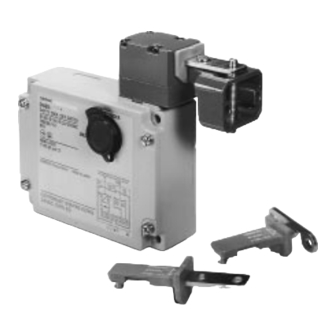
Safety-door Lock Switch
Protective Doors Are Locked Until
Machine Completely Stops
Operation
H
Select mechanical lock/solenoid release
or solenoid lock/mechanical release
models
H
Dedicated release lock ensures both
easy maintenance and door-unlock at
power failure
H
Tough aluminum die-cast unit
incorporating a switch box with IP67
enclosure rating (EN60529, IEC529)
H
Equipped with horizontal and vertical
conduit openings
H
Models available with LED indicators
H
Head can be rotated in 4 directions
H
Approved Standards
Agency
TÜV
Rheinland
UL
CSA
BIA
SUVA
Ordering Information
Conduit type
1/2-14NPT
(2
(2 conduits)
d it )
Note:
marking indicates the contacts which have positive opening mechanism approved by TÜV Rheinland.
Downloaded from
Elcodis.com
electronic components distributor
R
Standard
File No.
R9451050
EN60947-5-1
(IEC947-5-1,
VDE0660 Part 200, 206
)
UL508
E76675
CSA C22.2, No.14
LR45746
GS-ET-19
9402293
SUVA
5643
Lock type
Voltage for
Without Indicator
1NC
Solenoid
(Slow action)
Mechanical
24 VDC
D4BL-3CRA
lock
l
k
110 VAC
D4BL-3CRB
230 VAC
D4BL-3CRC
Solenoid lock
230 VAC
D4BL-3CRG
With Indicator
/+1NO+1NC
1NC
/+1NO+1NC
(Slow action)
D4BL-3CRA-A
D4BL-3CRB-A
D4BL-3CRC-A
D4BL-3CRG-A
D4BL
Without Indicator
With Indicator
2NC
+1NC
2NC
+1NC
(Slow action)
(Slow action)
D4BL-3DRA
D4BL-3DRA-A
D4BL-3DRB
D4BL-3DRB-A
D4BL-3DRC
D4BL-3DRC-A
D4BL-3DRG
D4BL-3DRG-A
Advertisement

Related Manuals for Omron D4BL


Summary of Contents for Omron D4BL
- Page 1 Safety-door Lock Switch D4BL Protective Doors Are Locked Until Machine Completely Stops Operation Select mechanical lock/solenoid release or solenoid lock/mechanical release models Dedicated release lock ensures both easy maintenance and door-unlock at power failure Tough aluminum die-cast unit incorporating a switch box with IP67...
-
Page 2: Specifications
3. Head Mounting Direction R: Right A: 1 mA at 10 to 115 VAC or VDC driving (with red and green indicator unit) Operation Key 1. Operation Key Type D4BL - K Horizontal mounting Vertical mounting Adjustable mounting Specifications RATINGS 1. - Page 3 D4BL D4BL 3. General Ratings Non-inductive load Inductive load Rated voltage Resistive load Lamp load Inductive load Motor load 125 VAC 10 A 1.5 A 10 A 2.5 A 250 VAC 10 A 10 A 1.5 A 8 VDC 10 A...
- Page 4 D4BL D4BL SOLENOID COIL CHARACTERISTICS Item 24 VDC models 110 VAC models 230 VAC models +10% Rated operating voltage 24 VDC (100% 110 VAC 10% (50/60 Hz) 230 VAC 10% (50/60 Hz) –15% Current consumption Approx. 300 mA Approx. 98 mA Approx.
- Page 5 10 to 115 VAC/DC internal terminals (terminals 31 and 12, 23 and 24, and 21 and 22) of the D4BL. 2. Each indicator unit must be connected in parallel with the contacts. When the contacts are open, the indicators will be lit.
- Page 6 D4BL D4BL OPERATING MODE (Example of Electromagnetic Interlock System Operating Mode of D4BL-jCjj) Operating mode Door The protective door is The protective door is The protective door is The protective door is open. closed. closed and the machine is closed and the solenoid is operating.
- Page 7 D4BL D4BL Application Examples CONNECTION EXAMPLE WITH OMRON’S G9S SAFETY RELAY UNIT G9S-301 (24 VDC)+D4BL-jCRG-j (Solenoid lock type)+D4D-j520 N Product Configuration Circuit Diagram PC output Motor control system Operation instruction D4BL G9S-301 output Closed Contactor Contactor D4DN Reset switch Open...
- Page 8 D4BL D4BL CONNECTION EXAMPLE WITH OMRON G9S SAFETY RELAY UNIT G9S-321-Tj (24 VDC)+D4BL-jCRA-j/-jCRB-j (Mechanical lock type)+D4D-j520N Circuit Diagram Product Configuration PC output Motor control system Operation instruction PC output A22E D4BL Contactor (off delay) Contactor (off delay) Closed D4DN (Reset signal)
- Page 9 D4BL D4BL Dimensions Unit: mm (inch) Note: Unless otherwise specified, a tolerance of 0.4 mm applies to all dimensions. SAFETY DOOR SWITCH D4BL-jjjj-j Four, M3.5 head clamp- ing screws (1.22) 116.5 (4.59) 10 (0.39) 17 (0.67) 7 (0.27) 37.5 (1.48) 34.2 (1.35)
- Page 10 37.8 (1.49) 5.3 (0.21) dia. 17.5 (0.69) 4 (0.16) dia. M4 bolt with hexag- onal hole 34.6 (1.36) WITH OPERATION KEY INSERTED D4BL + D4BL-K3 (side view) 81.5 min 85 max (3.21 min 3.35 max) (1.61) (1.57) 30 (1.18) INDICATOR UNIT Four terminal plates Two, 7 (0.28) dia.
-
Page 11: Installation
A UL2464-style cable is recommended. Apply sealing tape to the cable and conduit opening so that the D4BL can conform to IP67. Tighten the connector to a torque of 1.8 to 2.2 NSm (15.93 to 19.47 in lbs). Connect the Indicator Units to the D4BL after connecting the 7-con- ductor cable to the D4BL. - Page 12 D4BL D4BL Precautions MOUNTING Be sure to install a stopper as shown in the following illustration Switch Mounting Holes when mounting the Safety-door Lock Switch. The range of space “a” Four, M5 must be determined according to the available set zone 4 mm (0.16 inch) max.
- Page 13 OPERATION KEY The D4BL is provided with a shock absorptive damper when shipped attached to the D4BL in order to prevent the D4BL from be- ing damaged if it is dropped accidentally. Be sure to remove the shock absorptive damper after the D4BL is mounted.
- Page 14 Cover terminal Case Crimp-style terminal Case NOTE: DIMENSIONS SHOWN ARE IN MILLIMETERS. To convert millimeters to inches divide by 25.4. OMRON ELECTRONICS, INC. OMRON CANADA, INC. One East Commerce Drive 885 Milner Avenue Schaumburg, IL 60173 Scarborough, Ontario M1B 5V8...
Need help?
Do you have a question about the D4BL and is the answer not in the manual?
Questions and answers