Table of Contents
Advertisement
Quick Links
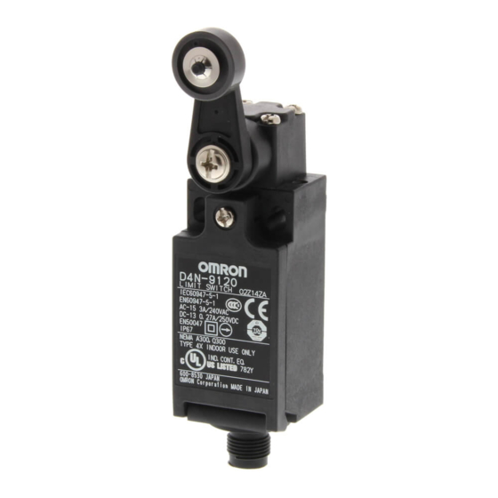
Safety Limit Switch
D4N
Upgraded Safety Limit Switches Based
on the Popular D4D, Providing a Full
Lineup Conforming to International
Standards
■ Lineup includes three contact models with 2NC/1NO and 3NC
contact forms in addition to the previous contact forms 1NC/
1NO, and 2NC. Models with MBB contacts are also available.
■ M12-connector models are available, saving on labor and
simplifying replacement.
■ Standardized gold-clad contacts provide high contact reliability.
Can be used with both standard loads and microloads.
■ Conforms to EN115, EN81-1, and EN81-2 (slow-action models
only).
■ Lineup includes both slow-action and snap-action models with
Zb contacts.
■ Certified standards: UL, EN (TÜV), and CCC
Be sure to read the "Safety Precautions" on page 18
and the "Precautions for All Safety Limit Switches" .
Model Number Structure
Model Number Legend
D4N-@@@@
1 2
3
1. Conduit size
1: Pg13.5 (1-conduit)
2: G1/2 (1-conduit)
3: 1/2-14NPT (1-conduit)
4: M20 (1-conduit)
5: Pg13.5 (2-conduit)
6: G1/2 (2-conduit)
7: 1/2-14NPT (2-conduit)
8: M20 (2-conduit)
9: M12 connector (1-conduit)
2. Built-in Switch
1: 1NC/1NO (snap-action)
2: 2NC (snap-action)
A: 1NC/1NO (slow-action)
B: 2NC (slow-action)
C: 2NC/1NO (slow-action)
D: 3NC (slow-action)
E: 1NC/1NO (MBB contact) (slow-action)
F: 2NC/1NO (MBB contact) (slow-action)
http://www.ia.omron.com/
Note: Contact your sales representative for details on models
with safety standard certification.
3. Head and Actuator
20: Roller lever (resin lever, resin roller)
22: Roller lever (metal lever, resin roller)
25: Roller lever (metal lever, metal roller)
26: Roller lever (metal lever, bearing roller)
2G: Adjustable roller lever, form lock (metal lever, resin roller)
2H: Adjustable roller lever, form lock (metal lever, rubber roller)
31: Top Plunger
32: Top Roller Plunger
62: One-way roller arm lever (horizontal)
72: One-way roller arm lever (vertical)
80: Cat whisker
87: Plastic rod
RE: Fork lever lock (right operation)
LE: Fork lever lock (left operation)
(c)Copyright OMRON Corporation 2007 All Rights Reserved.
1
Advertisement
Table of Contents

Related Manuals for Omron D4N Series


Summary of Contents for Omron D4N Series
- Page 1 RE: Fork lever lock (right operation) A: 1NC/1NO (slow-action) LE: Fork lever lock (left operation) B: 2NC (slow-action) C: 2NC/1NO (slow-action) D: 3NC (slow-action) E: 1NC/1NO (MBB contact) (slow-action) F: 2NC/1NO (MBB contact) (slow-action) http://www.ia.omron.com/ (c)Copyright OMRON Corporation 2007 All Rights Reserved.
- Page 2 D4N-812H D4N-822H D4N-8A2H D4N-8B2H Note: It is recommended that M20 be used for Switches to be exported to Europe and 1/2-14NPT be used for Switches to be exported to North American countries. http://www.ia.omron.com/ (c)Copyright OMRON Corporation 2007 All Rights Reserved.
- Page 3 D4N-8C2H D4N-8D2H D4N-8E2H D4N-8F2H Note: It is recommended that M20 be used for Switches to be exported to Europe and 1/2-14NPT be used for Switches to be exported to North American countries. http://www.ia.omron.com/ (c)Copyright OMRON Corporation 2007 All Rights Reserved.
- Page 4 Note: 1. It is recommended that M20 be used for Switches to be exported to Europe and 1/2-14NPT be used for Switches to be exported to North American countries. 2. Mechanically speaking, these models are basic limit switches. http://www.ia.omron.com/ (c)Copyright OMRON Corporation 2007 All Rights Reserved.
- Page 5 10 A 7,200 *1. Consult your OMRON representative for details. 240 VAC *2. Certification for CSA C22.2 No. 14 is authorized by the UL mark. *3. Ask your OMRON representative for information on certified Q300 models. Current (A) Volt-amperes (VA)
- Page 6 *4. This value will vary with the switching frequency, environment, and reliability level. Confirm that correct operation is possible with the actual load beforehand. *5. The mechanical durability of fork lever lock models is 10,000,000 operations min. http://www.ia.omron.com/ (c)Copyright OMRON Corporation 2007 All Rights Reserved.
- Page 7 (Only the NC contact side has a direct opening (Both NC contacts have a direct opening mechanism.) mechanism.) When contact welding occurs, the contacts are separated from each other by the plunger being pushed in. http://www.ia.omron.com/ (c)Copyright OMRON Corporation 2007 All Rights Reserved.
- Page 8 Note: Terminals are numbered according to EN50013 and the contact forms are according to IEC947-5-1. * MBB (Make Before Break) contacts have an overlapping structure, so that before the normally closed contact (NC) opens, the normally open contact (NO) closes. http://www.ia.omron.com/ (c)Copyright OMRON Corporation 2007 All Rights Reserved.
- Page 9 *3. For safe use, always make sure that the minimum values or greater *5. Reference values. are provided. *6. For safe use, always make sure that the minimum values or greater are provided. http://www.ia.omron.com/ (c)Copyright OMRON Corporation 2007 All Rights Reserved.
- Page 10 Conduit cap Two, 4 dia. holes 31 max. Depth: 5 Note: Unless otherwise specified, a tolerance of 0.4 mm applies to all dimensions. * Refer to page 12 for details on M12 connectors. http://www.ia.omron.com/ (c)Copyright OMRON Corporation 2007 All Rights Reserved.
- Page 11 (9 mm) (9 mm) provided. Direct opening travel DOT min. *7 3.2 mm 3.2 mm 5.8 mm 4.8 mm Direct opening force DOF min. *7 20 N 20 N 20 N 20 N http://www.ia.omron.com/ (c)Copyright OMRON Corporation 2007 All Rights Reserved.
- Page 12 *7. For safe use, always make sure that the minimum values or greater are provided. Direct opening travel DOT min. Direct opening force DOF min. *7 20 N 1-conduit M12 Connector D4N-9@@@ (14) M12 × 1 14.2 http://www.ia.omron.com/ (c)Copyright OMRON Corporation 2007 All Rights Reserved.
- Page 13 (18.5 (18.5 operation (NO) (MBB: 5 ) (MBB: 5 ) Snap-action (1NC/1NO) (2NC), Slow-action (2NC) (3NC) Model D4N-@@80 D4N-@@87 Operating characteristics Operating force OF max. 1.5 N 1.5 N Pretravel PT max. http://www.ia.omron.com/ (c)Copyright OMRON Corporation 2007 All Rights Reserved.
- Page 14 *3. Only for MBB models. are provided. *4. Reference value for MBB models. *5. Only for MBB models. *6. Reference value. *7. For safe use, always make sure that the minimum values or greater are provided. http://www.ia.omron.com/ (c)Copyright OMRON Corporation 2007 All Rights Reserved.
- Page 15 *5. Only for MBB models. *6. Reference value for MBB models only. *7. Only for MBB models. *8. Reference value. *9. For safe use, always make sure that the minimum values or greater are provided. http://www.ia.omron.com/ (c)Copyright OMRON Corporation 2007 All Rights Reserved.
- Page 16 Movement until switch operation (18.5 ) (18.5 ) (NO) (MBB: 5 ) Snap-action (1NC/1NO), Slow-action (2NC) (3NC) Model D4N-@@80 D4N-@@87 Operating characteristics Operating force OF max. 1.5 N 1.5 N Pretravel PT max. 15 http://www.ia.omron.com/ (c)Copyright OMRON Corporation 2007 All Rights Reserved.
- Page 17 55° to 60° surface surface 55° to 60° 5 to 9R 5 to 9R Dog setting range Dog setting range Note: Unless otherwise specified, a tolerance of 0.4 mm applies to all dimensions. http://www.ia.omron.com/ (c)Copyright OMRON Corporation 2007 All Rights Reserved.
-
Page 18: Safety Precautions
1.6 to 1.8 N·m Body mounting screw 0.5 to 0.7 N·m 1.8 to 2.2 N·m (except 1/2-14NPT) Connector, M12 adaptor 1.4 to 1.8 N·m (for 1/2-14NPT) Cap screw 1.3 to 1.7 N·m http://www.ia.omron.com/ (c)Copyright OMRON Corporation 2007 All Rights Reserved. - Page 19 Remove the screws from the front of the lever before mounting the lever in reverse (front/back), and set the level so that operation will be completed before exceeding a range of 180 on the horizontal. http://www.ia.omron.com/ (c)Copyright OMRON Corporation 2007 All Rights Reserved.
-
Page 20: Recommended Connectors
1. Make the rear edge of the dog smooth with an angle of 15 to 30 or make it in the shape of a quadratic curve. 2. Design the circuit so that no error signal will be generated. http://www.ia.omron.com/ (c)Copyright OMRON Corporation 2007 All Rights Reserved. -
Page 21: Dimensions (Unit: Mm)
Model D4N March 2006. Switch color Very similar Recommended Substitute Product Dimensions Very similar Wiring/connection Significantly different Sales of the D4N series commenced in January 2004. Mounting method Completely compatible Product Substitution Ratings/performance Very similar 1. Dimensions Operating characteristics Very similar... - Page 22 D4D-3A72N D4N-3B72 D4D-5172N D4N-5172 D4D-5572N D4N-5A72 D4D-5A72N D4N-5B72 D4D-6172N D4N-6172 D4D-6572N D4N-6A72 D4D-6A72N D4N-6B72 D4D-112HN D4N-112H D4D-152HN D4N-1A2H D4D-1A2HN D4N-1B2H D4D-212HN D4N-212H D4D-252HN D4N-2A2H D4D-2A2HN D4N-2B2H D4D-312HN D4N-312H D4D-352HN D4N-3A2H D4D-3A2HN D4N-3B2H http://www.ia.omron.com/ (c)Copyright OMRON Corporation 2007 All Rights Reserved.
- Page 23 D4D-5187N D4N-8187 D4D-5527N D4N-5A2H D4D-5A27N D4N-5B2H D4D-6187N D4N-6187 D4D-6527N D4N-6A2H D4D-6A27N D4N-6B2H D4D-1A80N D4N-4B80 D4D-2A80N D4N-2B80 D4D-3A80N D4N-3B80 D4D-5A80N D4N-8B80 D4D-6A80N D4N-6B80 D4D-1A87N D4N-4B87 D4D-2A87N D4N-2B87 D4D-3A87N D4N-3B87 D4D-5A87N D4N-8B87 D4D-6A87N D4N-6B87 http://www.ia.omron.com/ (c)Copyright OMRON Corporation 2007 All Rights Reserved.
-
Page 24: Operation
If the object touches the lever as shown below, the operating unstable, and the Limit Switch cannot maintain high reliability. position will not be stable. Furthermore, the Limit Switch cannot withstand strong vibration or shock. Incorrect Correct http://www.ia.omron.com/ (c)Copyright OMRON Corporation 2007 All Rights Reserved. - Page 25 3. Use or set a switch that is actuated in one direction only. (Also, set the switch for operation in one direction only.) 0.25 0.8 (TT) 80% of totaltravel 60 to 90 0.05 (low speed) http://www.ia.omron.com/ (c)Copyright OMRON Corporation 2007 All Rights Reserved.
- Page 26 When using the Limit Switch with a long lever or long rod lever, make sure that the lever is in the downward direction. V max. (m/s) 0.25 0.6 to 0.8 (TT) 0.5 to 0.7 (TT) http://www.ia.omron.com/ (c)Copyright OMRON Corporation 2007 All Rights Reserved.
- Page 27 With a roller actuator, the dog must touch the actuator at a right angle. The actuator or roller may deform or break if the dog touches the actuator (roller) at an oblique angle. Incorrect Correct Do not remove the Head. The Switch may fail. http://www.ia.omron.com/ (c)Copyright OMRON Corporation 2007 All Rights Reserved.
- Page 28 If the terminal is wired incorrectly, the Switch will not function. Furthermore, not only will the Switch have a negative influence on the external circuit, the Switch itself may become damaged or burnt. http://www.ia.omron.com/ (c)Copyright OMRON Corporation 2007 All Rights Reserved.
-
Page 29: Electrical Conditions
1.5 are uneven. to 2 times larger than the rated current to the Switch. When complying with EN certified ratings, use a 10-A IEC 60269- compliant gI or gG fuse. http://www.ia.omron.com/ (c)Copyright OMRON Corporation 2007 All Rights Reserved. - Page 30 ) (JIS C5003). The equation, 0.5×10 /operations indicates that the estimated malfunction rate is less than 1/2,000,000 operations with a reliability level of 60%. Unusable range 1 mA 100 mA 160 mA 1,000 Current (mA) http://www.ia.omron.com/ (c)Copyright OMRON Corporation 2007 All Rights Reserved.
-
Page 31: Operating Environment
Be sure to protect the Switch with a cover if the Switch is in a three months or more. location where the Switch may be actuated by mistake or where the Switch is likely cause an accident. Correct Incorrect Prevent false operation http://www.ia.omron.com/ (c)Copyright OMRON Corporation 2007 All Rights Reserved. - Page 32 Contact welding. characteristics Contact welding due to an incorrectly connected Change the circuit design. power source. Foreign materials or oil penetrated into the Use a protective box. contact area. http://www.ia.omron.com/ (c)Copyright OMRON Corporation 2007 All Rights Reserved.
-
Page 33: Incorrect Wiring
Lead Crimp terminal Terminal Terminal screw screw Terminal Terminal Incorrect Wiring Incorrect Crimped location facing down Lead Crimp terminal Terminal Terminal screw screw Terminal Terminal Too close to maintain dielectric strength C-10 http://www.ia.omron.com/ (c)Copyright OMRON Corporation 2007 All Rights Reserved. - Page 34 • Related International Standards: ISO 12100 Basic Concepts, General Principles for Design IEC 61508 Functional Safety of Electrical/Electronic/Programmable Electronic Safety-related Systems http://www.ia.omron.com/ (c)Copyright OMRON Corporation 2007 All Rights Reserved.
- Page 35 Warranty and Limitations of Liability WARRANTY OMRON's exclusive warranty is that the products are free from defects in materials and workmanship for a period of one year (or other period if specifi ed) from date of sale by OMRON. OMRON MAKES NO WARRANTY OR REPRESENTATION, EXPRESS OR IMPLIED, REGARDING NON-INFRINGEMENT, MERCHANTABILITY, OR FITNESS FOR PARTICULAR PURPOSE OF THE PRODUCTS.
Need help?
Do you have a question about the D4N Series and is the answer not in the manual?
Questions and answers