Table of Contents
Advertisement
Quick Links
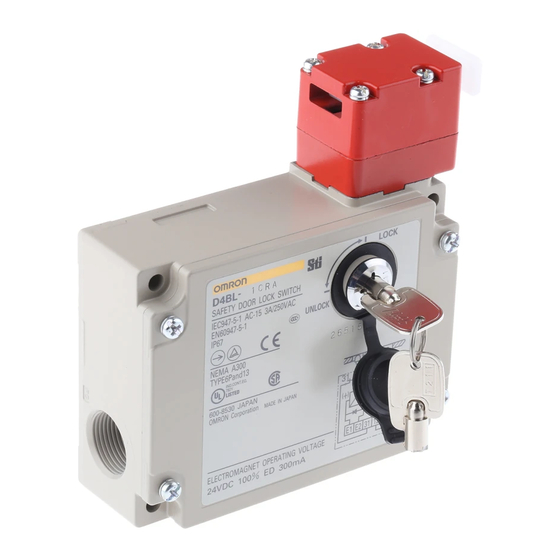
Guard Lock Safety-door Switch
D4BL
Die-cast aluminum body
Key holding force of 700 N
• Auxiliary release key ensures easy maintenance and unlocks the
door in the case of a power failure.
• Die-cast aluminum body incorporating a switch box with degree
of protection satisfying IP67, UL, and CSA TYPE6P, 13.
• Equipped with a horizontal and vertical conduit outlet.
• Models incorporating easy-to-see indicators for monitoring and
those using an adjustable Operation Key for a swinging door are
available.
• The mounting direction of the head can be changed to allow the
Operation Key to be inserted from four directions.
Be sure to read the "Safety Precautions" on page 11.
Model Number Structure
Model Number Legend
Switch
D4BL -
1
2
3
4
1. Conduit Outlet (2-conduit type)
1: PG13.5
2: G1/2
4: M20
2. Built-in Switch (with Door Open/Closed Detection Switch and
Lock Monitor Switch Contacts)
C: 1NC/1NO (slow-action) + 1NC (slow-action)
D: 2NC (slow-action) + 1NC (slow-action)
3. Head Mounting Direction
R: Four mounting directions possible (right-side mounting at
shipping)
4. Door Lock and Release (Auxiliary Release Key is Incorporated
by All Models)
A: Mechanical lock/24 VDC solenoid release
G: 24 VDC Solenoid lock/Mechanical release
5. Indicator
Blank: Without indicator
A: 10 to 115 VAC or VDC driving (with orange and green LED
indicator unit)
-
5
For the most recent information on models that have been certified
for safety standards, refer to your OMRON website.
Operation Key
D4BL - K
1
1. Operation Key Type
1: Horizontal mounting
2: Vertical mounting
3: Adjustable mounting (Horizontal)
CSM_D4BL_DS_E_10_3
1
Advertisement
Table of Contents

Related Manuals for Omron D4BL


Summary of Contents for Omron D4BL
- Page 1 Operation Key to be inserted from four directions. For the most recent information on models that have been certified for safety standards, refer to your OMRON website. Be sure to read the “Safety Precautions” on page 11. Model Number Structure...
-
Page 2: Ordering Information
A: Equipped with an orange/green LED display unit Ordering Information List of Models Switches (Operation Keys are sold separately.) Consult with your OMRON representative when ordering any models that are not listed in this table. Voltage Without indicator With LED indicator... - Page 3 Conforms to the following EC Directives: Certified Standards • Machinery Directive Certification body Standard File No. • EN ISO 14119 EN60947-5-1 • EN 60204-1 (certified direct Consult your OMRON TÜV Rheinland opening) representative for details. GS-ET-19 UL508 E76675 CSA C22.2, No.14 LR45746 Consult your OMRON CQC (CCC) GB14048.5...
- Page 4 Although the switch box is protected from dust, oil or water penetration, do not use the D4BL in places where dust, oil, water, or chemicals may enter through the key hole on the head, otherwise Switch damage or malfunctioning may occur.
- Page 5 Extraction The terminals 11-12 insertion completion completion and 21-22 can be position position used as unlike poles. Note: The EN-certified direct opening mechanism is indicated by on the Switch. Contact Form (D4BL-2GRD-AT) 12 (Safety circuit side) 22 (Monitor circuit side)
- Page 6 D4BL Dimensions and Operating Characteristics (Unit: mm) Switches D4BL-@@R@-@ Four, M3.5 head clamping screws (116.5) 31.5 37.5 Lock 34.2 protection Four, 5.3 dia. (123.5) Operating Model mounting D4BL-@@R@-@ Characteristics holes 74±0.1 Four, M4 Key insertion force 19.61 N max. cover Key extraction force 19.61 N max.
-
Page 7: Operation Keys
D4BL Operation Keys D4BL-K1 D4BL-K3 78.7 Long mounting hole 40.7 7.3 15 25.8 15.6 Two, 2.65R 11.8 4 dia. D4BL-K2 18 ° 15.6 53.7 5.3 x 7.3 long mounting hole 18 ° (80.7) 25.8 52.4 15.6 11.8 19.5 (37.8) 5.3 11.9 7.5 4 dia. - Page 8 D4BL With Operation Key Inserted D4BL + D4BL-K1 D4BL + D4BL-K2 D4BL + D4BL-K3 Surface A Horizontal direction Operation Key Horizontal direction Horizontal direction insertion radius Operation Key Operation Key R ≥ 250 *2 insertion radius insertion radius R ≥ 1200 *1 R ≥...
- Page 9 D4BL Indicator Unit Four terminal plates Two, 7 dia. Two LED (16) 26.8 53.2 57.2 (16) 10.6 (12.6) (35) 26.2 (61.2) Connections Internal Circuit Diagram Indicator Solenoid 24 VDC 10 to 115 VAC/VDC E1 (+) E2 (−) Constant-current diode...
- Page 10 D4BL Circuit Connection Example • Terminals 11 and 32 are connected internally. • When using indicators, connect them to the auxiliary circuit side (monitor circuit) or in parallel between E1 and E2 as shown below. • Do not connect the indicators in parallel with the direct opening contact. If the indicators are broken, a short-circuit current may flow, causing equipment to malfunction.
-
Page 11: Safety Precautions
D4BL Safety Precautions ● Be sure to read the precautions for All Safety Door Switches in the website at: http://www.ia.omron.com/. Precautions for Correct Use DANGER Injury may occasionally occur. Always check to make Appropriate Tightening Torque sure that the safety functions operate correctly before Loose screws may result in malfunction. -
Page 12: Mounting Dimensions
30±0.1 Operation Key Operation plunger and Rotation lever and • The D4BL is provided with a shock-absorbing damper to protect groove mechanism protruding part the D4BL from damage that may result from dropping the D4BL Normal Positions of Rotating Lever and Plunger during transportation. - Page 13 • The following procedures are recommended for mounting and wiring the indicator unit securely. • To ensure IP67, use OMRON’s SC-@M and Nippon Flex’s ABS-08Pg13.5 and ABS-12 Pg13.5 Connectors. • Recommended cable: UL2464-type cable that is AWG20 to AWG18 (0.5 to 1.0 mm...
-
Page 14: Terms And Conditions Agreement
(a) Exclusive Warranty. Omron’s exclusive warranty is that the Products will be free from defects in materials and workmanship for a period of twelve months from the date of sale by Omron (or such other period expressed in writing by Omron). Omron disclaims all other warranties, express or implied.
Need help?
Do you have a question about the D4BL and is the answer not in the manual?
Questions and answers