Edge-Core ECS2100-10T TIP Quick Start Manual
10/28/52-port gigabit web-smart pro switches
Hide thumbs
Also See for ECS2100-10T TIP:
- Reference manual (725 pages) ,
- Installation manual (51 pages) ,
- Quick start manual (9 pages)
Advertisement
Available languages
Available languages
Quick Star t Guide
10/28/52-Port Gigabit Web-Smart Pro Switches
ECS2100-10T TIP/ECS2100-10P TIP/ECS2100-10PE TIP
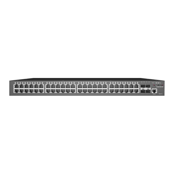
ECS2100-28T TIP/ECS2100-28P TIP/ECS2100-28PP TIP/ECS2100-52T TIP
1. Unpack the Device and Check Contents
Rack Mounting Kit—two brackets and eight screws
Four adhesive foot pads
Power Cord—either Japan, US, Continental Europe
or UK
Console Cable—RJ-45 to DB-9 (Optional item)
Documentation—Quick Start Guide (this document)
and Safety and Regulatory Information
Note:
The ECS2100 TIP series devices are for indoor use only.
Note:
For Safety and Regulatory information, refer to the
Safety and Regulatory Information document included with
the device.
Note:
Other documentation, including the Installation Guide,
Web Management Guide, and CLI Reference Guide, can be
obtained from www.edge-core.com.
2. Mount the Device
a. Mounting in a Rack
ECS2100-10T TIP
ECS2100-10PE TIP
ECS2100-10P TIP
ECS2100-28T TIP
ECS2100-28P TIP
ECS2100-28PP TIP
ECS2100-52T TIP
1
2
1
Attach the brackets to the device.
2
Use the screws and cage nuts supplied with the rack to
secure the device in the rack.
Caution:
Installing the device in a rack requires two people.
One person should position the device in the rack, while the
other secures it using the rack screws.
Attention:
Deux personnes sont nécessaires pour installer
un commutateur dans un bâti: La première personne va
positionner le commutateur dans le bâti, la seconde va le
fixer avec des vis de montage.
Note:
The device can also be installed on a desktop or shelf
using the included adhesive rubber foot pads.
b. Mounting in a Rack (ECS2100-10PE TIP only)
2
Caution:
For safe operation, install the device with RJ-45
ports facing up.
Attention:
Pour un fonctionnement sûr, installez le
commutateur avec les ports RJ-45 orientés vers le haut.
1
Set two screws in the wall 150 mm (5.9 in.) apart.
2
Slide the device's wall mounting slots down onto the screws
so that the unit is secure.
3. Ground the Device
1
2
Ensure the rack on which the device is to be mounted is
1
properly grounded and in compliance with ETSI ETS 300 253.
Verify that there is a good electrical connection to the
grounding point on the rack (no paint or isolating surface
treatment).
2
Attach a lug (not provided) to a #12 AWG (PoE device) or #18
AWG (non-PoE device) minimum grounding wire (not
provided), and connect it to the grounding point on the
device rear panel. Then connect the other end of the wire to
rack ground.
– 1 –
1
E042024-AP-R01
150200002715A
Advertisement
Table of Contents

Related Manuals for Edge-Core ECS2100-10T TIP


Summary of Contents for Edge-Core ECS2100-10T TIP
- Page 1 Quick Star t Guide 10/28/52-Port Gigabit Web-Smart Pro Switches ECS2100-10T TIP/ECS2100-10P TIP/ECS2100-10PE TIP ECS2100-28T TIP/ECS2100-28P TIP/ECS2100-28PP TIP/ECS2100-52T TIP 1. Unpack the Device and Check Contents Attach the brackets to the device. Use the screws and cage nuts supplied with the rack to ECS2100-10T TIP secure the device in the rack.
-
Page 2: Connect Power
Verify that the external AC power requirements for the device can be met as listed below: ECS2100-10T TIP: AC 100-240 V, 50-60 Hz, 0.5 A ECS2100-10P TIP: AC 100-240 V, 50-60 Hz, 2.1 A ECS2100-28T TIP: AC 100-240 V, 50-60 Hz, 0.5 A (Not for China), AC 100-240 V, 50/60 Hz, 0.5 A... -
Page 3: Connecting To The Web Interface
Note: The TIP OpenWiFi SDK default URL of the DigiCert certificate is set to ecOpen: (https:// cloud.openwifi.ignitenet.com). If you want to register the device to your own TIP OpenWiFi SDK, contact oxherd@edge-core.com to change the default URL. – 3 –... -
Page 4: Hardware Specifications
Device Chassis Safety UL/CUL (UL 62368-1, 2nd Ed & CAN/CSA C22.2 Size (W x D x H) ECS2100-10T TIP: 19.64 x 11.71 x 3.66 cm (7.73 x No. 62368-1-14, 2nd Edition) 4.61 x 1.44 in.) CB (IEC/EN 62368-1) ECS2100-10P TIP: 33.0 x 20.4 x 4.26 cm (12.99 x BSMI CNS15598-1 8.03 x 1.67 in.) - Page 5 快速入门指南 10/28/52端口智慧型交换机 ECS2100-10T TIP/ECS2100-10P TIP/ECS2100-10PE TIP ECS2100-28T TIP/ECS2100-28P TIP/ECS2100-28PP TIP/ECS2100-52T TIP 小心: 将此设备安装在机架中时需要两个人。一个人将 1. 产品包装内容 设备放置在机架中,同时另一个人用机架螺丝将其固 定。 ECS2100-10T TIP 注意: 也可以使用附带的粘合型支脚垫将设备安装到桌 面或搁架上。 ECS2100-10PE TIP ECS2100-10P TIP b. 壁挂 ( 仅适用 ECS2100-10PE TIP) ECS2100-28T TIP ECS2100-28P TIP ECS2100-28PP TIP ECS2100-52T TIP 安装套件...
- Page 6 6. 执行初始配置 将 AC 电源线插入背板 AC 电源孔。 连接 AC 电源到交换器电源插孔,各型号电源规格如下: ECS2100-10T TIP: AC 100-240 V, 50-60 Hz, 0.5 A ECS2100-10P TIP: AC 100-240 V, 50-60 Hz, 2.1 A ECS2100-28T TIP: AC 100-240 V, 50-60 Hz, 0.5 A 不适用于中 国 , AC 100-240 V, 50/60 Hz, 0.5 A ECS2100-28P TIP: AC 100-240 V, 50-60 Hz, 3.2 A...
- Page 7 使用随机附上的连接线连接 EPS460W 与 ECS2100-28PP。 注意:TIP OpenWiFi SDK 默认的 DigiCert 证书网址设置 为 ecOpen:(https://cloud.openwifi.ignitenet.com)。 连接 EPS460W 电源,看到 EPS460W 电源灯已经亮起, 如果您想要将设备注册到您自己的 TIP OpenWiFi SDK, 表示已经开始供电。 请联系 oxherd@edge-core.com 更改默认网址。 9. 初始设置与注册 设备连接网络的方式有两种: 当设备通过网络端口首次连接到互联网时,它会自动重定向到 ecOpen (https://cloud.openwifi.ignitenet.com/) 。 请输入设 备的 MAC 地址和序列号进行注册。 设备默认通过 DHCP 获取 IP 地址。如果设备无法连接到...
- Page 8 设备机箱 UL/CUL (UL 62368-1, 2nd Ed & CAN/CSA C22.2 安全 No. 62368-1-14, 2nd Edition) 尺寸 (W x D x H) ECS2100-10T TIP: 19.64 x 11.71 x 3.66 cm (7.73 x CB (IEC/EN 62368-1) 4.61 x 1.44 英寸 ) BSMI CNS15598-1 ECS2100-10P TIP: 33.0 x 20.4 x 4.26 cm (12.99 x...
- Page 9 快速入門指南 10/28/52埠智慧型交換器 ECS2100-10T TIP/ECS2100-10P TIP/ECS2100-10PE TIP ECS2100-28T TIP/ECS2100-28P TIP/ECS2100-28PP TIP/ECS2100-52T TIP 警告 : 需要兩個人,將設備裝到機櫃上。一人負責固定 1. 拆開設備包裝並檢查內容物 設備在機櫃上之位置,另一人負責用機櫃螺絲固定。 注意 : 也可以使用附帶的橡膠腳墊安裝在桌面或架上。 ECS2100-10T TIP ECS2100-10PE TIP 壁掛 ( 僅適用於 ECS2100-10PE TIP) ECS2100-10P TIP ECS2100-28T TIP ECS2100-28P TIP ECS2100-28PP TIP ECS2100-52T TIP 機架安裝套件包含 2 個擴充托架、8 個用於固定托...
- Page 10 6. 初始設定 將 AC 電源線插入背板 AC 電源孔。 連接 AC 電源到設備電源插孔,各型號電源規格如下: ECS2100-10T TIP: AC 100-240 V, 50-60 Hz, 0.5 A ECS2100-10P TIP: AC 100-240 V, 50-60 Hz, 2.1 A ECS2100-28T TIP: AC 100-240 V, 50-60 Hz, 0.5 A 不適用於中 國 , AC 100-240 V, 50/60 Hz, 0.5 A ECS2100-28P TIP: AC 100-240 V, 50-60 Hz, 3.2 A...
- Page 11 入網頁介面。 注意:TIP OpenWiFi SDK 預設的 DigiCert 憑證網址設定 使用隨機附上的連接線連接 EPS460W 與 ECS2100-28PP 為 ecOpen (https://cloud.openwifi.ignitenet.com)。 TIP。 如果您想要將裝置註冊到您自己的 TIP OpenWiFi SDK, 連接 EPS460W 電源,看到 EPS460W 電源燈已經亮起, 請聯繫 oxherd@edge-core.com 變更預設網址。 表示已經開始供電。 9. 初始設定與註冊 設備連接網路有兩種設定方式: 當裝置透過網路埠首次連上網路時,它會自動導引至 ecOpen https://cloud.openwifi.ignitenet.com/)。 請輸入裝置的 MAC 地址和序列號碼進行註冊。 預設情況下,裝置會透過 DHCP 取得 IP 地址。 如果裝置無法連...
- Page 12 EN 55035 抗擾性 IEC 61000-4-2/3/4/5/6/11 機殼規格 UL/CUL (UL 62368-1, 2nd Ed & CAN/CSA C22.2 ECS2100-10T TIP: 19.64 x 11.71 x 3.66 cm (7.73 x 尺寸 No. 62368-1-14, 2nd Edition) 安全性 (W x D x H) 4.61 x 1.44 吋 ) CB (IEC/EN 62368-1) ECS2100-10P TIP: 33.0 x 20.4 x 4.26 cm (12.99 x...
Need help?
Do you have a question about the ECS2100-10T TIP and is the answer not in the manual?
Questions and answers