
Related Manuals for Alfa Laval OS12


Summary of Contents for Alfa Laval OS12
- Page 1 Alfa Laval OS Twin Screw Pump 3205-0000 Instruction Manual Lit. Code 200007996-1-EN-GB BRITISH ENGLISH...
- Page 2 © Alfa Laval Corporate AB 2023-04 This document and its contents are subject to copyrights and other intellectual property rights owned by Alfa Laval Corporate AB. No part of this document may be copied, re-produced or transmitted in any form or by any means, or for any purpose, without Alfa Laval Corporate AB’s prior express written permission. Information and services provided in this document are made as a benefit and service to the user, and no representations or warranties are made about the accuracy or suitability of this information and these services for any purpose.
-
Page 3: Table Of Contents
Double Seal OS1x....................46 Double Seal OS2x, OS3x, OS4x................49 Heating (option).......................52 6.10 Rectangular Inlet (option)..................53 6.11 Troubleshooting.......................54 7 Technical Data ......................55 Pumphead Clearance information................59 8 Spare Parts .........................61 Ordering Spare Parts....................61 Alfa Laval Service....................61 9 Parts List and Exploded View ................ 63... -
Page 5: Declarations Of Conformity
Company name, address and phone number Hereby declare that Pump Designation OS12, OS14, OS16, OS22, OS24, OS26, OS27, OS28, OS32, OS34, OS36, OS37, OS38, OS42, OS44, OS46 Type Serial number from E10.000 to E1.000.000 Serial number from AAX000000001 to AAX999999999 is in conformity with the following directives with amendments: •... -
Page 6: Declaration Of Conformity
Company name, address and phone number Hereby declare that Pump Designation OS12, OS14, OS16, OS22, OS24, OS26, OS27, OS28, OS32, OS34, OS36, OS37, OS38, OS42, OS44, OS46 Type Serial number from E10.000 to E1.000.000 Serial number from AAX000000001 to AAX999999999 is in conformity with the following directives with amendments: •... -
Page 7: General Description
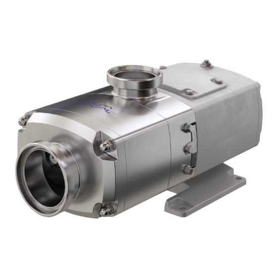
2 General Description The Alfa Laval OS range of pumps is of conventional Twin Screw pump design with the positive displacement being provided by non-contacting, contra rotating screws within a fully swept pump chamber. Handling from low to high viscosity pumped media, the pump’s characteristic smooth, low shear pumping action is ideal in application areas such as Dairy, Food, Beverage, Home &... -
Page 9: Safety
Not following the instructions can result in serious accidents. This documentation describes the authorized way to use the supplied product. Alfa Laval will take no responsibility for injury or damage if the equipment is used in any other way. This Instruction manual is designed to provide the user with the information to perform tasks safely for all phases in the lifetime of the supplied product. - Page 10 Always have the pump electrically connected by authorized personnel. (See the motor in- struction supplied with the drive unit) Alfa Laval recommends the supply disconnecting device shall be in accordance with EN 60204-1. Operation Never stand on the pump or pipelines.
- Page 11 Always ensure that the unit is securely fixed during transportation Always use original packaging or similar during transportation Always use a suitable transport device i.e. forklift truck or pallet lifter Storage Ideally, as a guide Alfa Laval recommend: • Store supplied product as supplied in original packaging •...
-
Page 12: Warning Signs In Text
Procedure in case of non-acceptance: • Fix and/or replace the protective device How to contact Alfa Laval Contact details for all countries are continually updated on our website. Please visit www.alfalaval.com to access the information directly. 3.2 Warning Signs in Text Pay attention to the safety instructions in this manual. -
Page 13: Requirements Of Personnel
How to contact Alfa Laval Contact details for all countries are continually updated on our website. Please visit www.alfalaval.com to access the information directly. -
Page 14: Recycling Information
Besides the equipment itself, any hazardous residues from the process liquid must be considered and dealt with in a proper manner. When in doubt, or in the absence of local regulations, please contact your local Alfa Laval sales company. 200007996-1-EN-GB... -
Page 15: Introduction
This provides a robust and reliable platform that offers greater process flexibility. Designed for process flexibility, the Alfa Laval Twin Screw Pump is built on a robust, reliable platform that meets stringent hygienic standards. It is capable of handling both product transfer and CIP. -
Page 17: Installation
5 Installation 5.1 Unpacking, Handling and Storage NOTE Always ensure any personnel undertaking lifting operations have the suitable experience and training to do so safely. Always ensure any lifting equipment used is in good condition and has been suitably tested, using lifting logs when applied. - Page 18 5 Installation After receipt and inspection: If the pump is not to be installed immediately, the pump should be repacked in the original packaging and placed in suitable storage. The following points should be noted: • Plastic or gasket type port covers should be left in place •...
-
Page 19: System Design And Installation
Installation 5 5.2 System Design and Installation NOTE To ensure optimum operation it is important that any pump unit is installed correctly. When designing a pumping system the following should be taken into consideration. Design: • Confirm the Net Positive Suction Head (NPSH) available from the system exceeds the NPSH required by the pump, as this is crucial for ensuring the smooth operation of the pump and preventing cavitation. - Page 20 5 Installation Pump Lubrication: The pump will be supplied filled with food grade oil with NSF/NSDA H1 Approval. The oil level can be checked using the oil site glass on the side of the gearbox. Oil level must be checked with the pump not running.
- Page 21 Installation 5 The drawings above shows two typical methods for foundation bolt retaining. The sleeve allows for “slight” lateral movement of the bolts after the foundation is poured. Rag or wastepaper can be used to prevent the concrete from entering the sleeve while the foundation is poured.
- Page 22 5 Installation The following dimensions and tolerances apply to standard supply couplings only. Measure 4 positions at 90° around coupling Coupling size Dimension A Maximum 0.3 mm (0.011 inch) 0.3 mm (0.011 inch.) 0.3 mm (0.011 inch.) 0.4 mm (0.015 inch.) 0.4 mm (0.015 inch.) 0.4 mm (0.015 inch.) 0.5 mm (0.019 inch.)
-
Page 23: Flushing Seal Arrangement And Pre-Start Up Checks
Installation 5 5.3 Flushing seal arrangement and pre-start up checks A flushed seal arrangement is fitted in order to cool or clean the seal area. It is important that: • The flush is correctly connected on both sides for the seals (see below). •... - Page 24 5 Installation Flushing pressure and flow rate Single flushed mechanical seal 0.5 bar (7 psi) maximum. Any further increase in pressure will result in lip seal failure. Double flushed mechanical seal 16 bar (232 psi) maximum or 6 bar (87 psi) over product pressure. The flushing flow rate must be adequate to ensure that the temperature limitation of the seals is not exceeded.
-
Page 25: Maintenance
Slow rotation with the shaft is possible if the pump has a single flushed seal or double shaft seal (<100 1/min). The OS Twin Screw pumps are only suitable for the SIP (Sterilisation In Place) method in consultation with Alfa Laval. Suitability depends on the choice of elastomers. The maximum sterilisation temperature is 145°C (293°F). -
Page 26: Maintenance Schedule
6 Maintenance 6.2 Maintenance Schedule It is advisable to install pressure gauges on both sides of the pump so that any problems within the pump/pipework can be monitored. Maintenance schedule: Your weekly schedule should include: • Checking the seals for leakage •... -
Page 27: Dismantling
Maintenance 6 6.3 Dismantling NOTE Before disassembling the pump refer to safety precautions. See Parts List and Exploded View on page 63 for exploded view drawings. Removing pump cover and pump casing: 1. Remove front cover nuts, washers, front cover, front cover elastomer and pump 3205-0010 casing Removing feed screws:... - Page 28 6 Maintenance Removing seal housing: 1. Remove the seal housing retention screws 2. Tap both sides of the seal housing with a soft mallet 3205-0015 3. Withdraw the seal housing along the pump casing studs to remove Disassembling of gearbox: 1.
- Page 29 Maintenance 6 Disassembling of front gearbox: 1. Remove gear top cover bolts, washers, gear top cover and gear cover O-ring 2. Remove lip seals 3. Remove needle bearing snap ring 4. Tap the needle bearings outer races out of their seat 3205-0018 Disassembling of bearing housing shaft assembly:...
- Page 30 6 Maintenance Removing bearing and gear: 1. Mount the shaft vertically in a press (splines pointing down) with a tool positively located against the gear and apply pressure to the top of the shaft so that the shaft passes through the bearings and gear.
- Page 31 Maintenance 6 Disassembly of adjustable timing gear: 1. Remove timing gear assembly bolts and washers 2. Remove timing gear clamping plate and 3205-0023 timing gear from gear sleeve Remove lip seal from gearbox end cover: 1. Extract the lip seal from the gearbox end cover.
-
Page 32: Assembly
6 Maintenance 6.4 Assembly Take care not to damage shaft surfaces, in particular where bearings and lipseals will be located. Ensure all fastenings are tightened to the torque settings as shown in Technical Data (See Technical Data on page 55) Assembly of adjustable gear. - Page 33 Maintenance 6 Fitting bearings to shaft. 1. Fix the shaft vertically in a vice fitted with soft jaws- taking care not to damage the shaft 2. Heat needle bearing inner race up to 110°C (230°F) and shrink fit it onto its seat 3.
- Page 34 6 Maintenance Install lip seal in gearbox end cover. 1. Install lip seal in gearbox end cover 3205-0031 Fitting shaft assembly in gearbox end cover. Ensure correct torques are used. 1. Slide drive and auxiliary shaft assembly in gearbox end cover (Take care not to damage the lip seal ) 3205-0032 2.
- Page 35 Maintenance 6 Assembling of gearbox. Ensure correct torques are used. 1. Fit gearbox O-Ring use grease to keep it in place 2. Push in the shaft assembly into the front gearbox. (take care not to damage the lip seals ). Ensure that the drive shaft is in 3205-0034 the correct position to realign with the motor coupling...
- Page 36 6 Maintenance Installing primary seal components. Ensure correct torques are used. 1. Lubricate external elastomers 2. Slide cartridge seal over shaft ensuring 3205-0037 that the seal drive flat (OS2x/OS3x/OS4x) or seal drive lug (OS1x) aligns with the corresponding flat (OS2x/OS3x/OS4x) or cut-out (OS1x) in the seal housing.
- Page 37 Maintenance 6 Setting feed screw timing. Ensure correct torques are used. 1. Make sure the gear sleeve bolts are loose, and the gear rotates on the sleeve 2. Turn the drive shaft and check the clearance between the feed screw flanks. Use feeler gauges to make sure the 3205-0040 clearance is evenly divided between the...
- Page 38 6 Maintenance Fitting pump casing and front cover. Ensure correct torques are used. 1. Fit the pump casing elastomer in seal 3205-0041 housing and front cover 2. Fit pump casing over feed screws and engage with dowels (Attention, ensure the housing is in the same orientation as it was before it was removed) 3.
- Page 39 Maintenance 6 Adding lubricant: 1. Pour the recommended oil lubricant into the gear top cover opening. (See Technical Data on page 55 for correct oil quality.) 2. Fit gear top cover 3. Fit the gear top cover and fix it with bolts and washers 3205-0042 200007996-1-EN-GB...
-
Page 40: Maintenance Seals - Single Seal - All Models
6 Maintenance 6.5 Maintenance seals - Single Seal - All Models 3205-0047 3205-0079 Assembly Check that all parts are accounted for and ensure no parts are damaged. Seal faces are brittle, and care must be taken not to chip these components during fitting of the seal. Ensure seal faces are clean throughout the fitment. - Page 41 Maintenance 6 Lightly lubricate elastomer (82) with suitable lubricant and fit into rotary holder (71) groove. Align the slots in the rotary face (73) with the pins fitted in the rotary holder bore (71), then firmly press the rotary face (73) fully home into the rotary holder bore (71).
- Page 42 6 Maintenance Validate the assembly by compressing the seal a few times, making sure it springs back out each time. Carefully fit the mechanical seal onto the shaft and into the pump housing making sure the flat of the seal housing aligns with the flat in the pump housing and fit seal retaining screw and gland guard.
-
Page 43: Single Flushed Seal - All Models
Maintenance 6 6.6 Single Flushed Seal - All Models 3205-0048 3205-0080 Assembly Check that all parts are accounted for and ensure no parts are damaged. Seal faces are brittle, and care must be taken not to chip these components during fitting of the seal. Ensure seal faces are clean throughout the fitment. - Page 44 6 Maintenance Lightly lubricate elastomer (82) with suitable lubricant and fit into rotary holder (71) groove. Align the slots in the rotary face (73) with the pins fitted in the rotary holder bore (71), then firmly press the rotary face (73) fully home into the rotary holder bore (71).
- Page 45 Maintenance 6 Lightly lubricate O-ring (85) and fit onto the seal housing (88). Lightly lubricate outside diameter of lip seal (90). Firmly press the lip seal (90) fully home into the housing bore (88). Fit circlip (91) into the groove in the seal housing (88).
-
Page 46: Double Seal Os1X
6 Maintenance 6.7 Double Seal OS1x 3205-0078 3205-0081 Assembly Check that all parts are accounted for and ensure no parts are damaged. Seal faces are brittle, and care must be taken not to chip these components during fitting of the seal. Ensure seal faces are clean throughout the fitment. - Page 47 Maintenance 6 Lightly lubricate the seal housing profile elastomer (83) and fit onto the seal housing (74). Lightly lubricate O-ring (85) and fit onto the seal housing (74). Align radial pins in drive ring (75) with the anti-rotation slots in seal housing (74). Fit drive ring (75) into housing (74) making sure the coil springs holes in the drive ring (75) are facing inwards.
- Page 48 6 Maintenance Pick seal housing (74) assembly up and whilst holding the assembly compressed, turn it around and slide over shaft sleeve (93) mating the rotary face (77) and static face (76). Lightly lubricate profile elastomer (80) and fit to the rotary holder (94). Place plastic washer (81) in rotary holder (78) aligning the slots in the washer (81) with the pins fitted in the rotary holder bore (94).
-
Page 49: Double Seal Os2X, Os3X, Os4X
Maintenance 6 6.8 Double Seal OS2x, OS3x, OS4x 3205-0051 3205-0082 Assembly Check that all parts are accounted for and ensure no parts are damaged. Seal faces are brittle, and care must be taken not to chip these components during fitting of the seal. Ensure seal faces are clean throughout the fitment. - Page 50 6 Maintenance Lightly lubricate elastomer (82) with suitable lubricant and fit into rotary holder (71) groove. Align the slots in the rotary face (73) with the pins fitted in the rotary holder bore (71), then firmly press the rotary face (73) fully home into the rotary holder bore (71).
- Page 51 Maintenance 6 Lightly lubricate O-ring (92) and fit onto the rotary face (77). Gently place rotary face (77) onto the coil springs (87) while aligning the pin-slots with the pins in the drive ring (78). Make sure all coil springs sit firmly in all coil spring holes. Spray acetone or similar solvent onto lint free tissue and wipe the sealing surfaces of the rotary faces (73)(77) and static faces (72)(76)
-
Page 52: Heating (Option)
Ensure the pump is connected to the heating supply in the correct way. Refer to connection size for pump models in the table. Heating Connections Size OS12, OS14, OS16 G1/4” (1/4” NPT) OS22, OS24, OS26, G1/4” (1/4” NPT) OS27, OS28 OS32, OS34, OS36, G1/4”... -
Page 53: Rectangular Inlet (Option)
The mating adaptor and gaskets/seals should conform to country specific hygienic regulations such as 3A. For sizes please see diagram and table below. Dimension Model OS22, OS24, OS26, OS32, OS34, OS36, OS12, OS14, OS16 OS42, OS44, OS46 OS27, OS28 OS37, OS38 200007996-1-EN-GB... -
Page 54: Troubleshooting
6 Maintenance 6.11 Troubleshooting Problem Problem Causes Solution √ √ Incorrect direction of rotation. Reverse motor. √ Pump not primed. Expel gas from suction line and pumping chamber and introduce fluid. Increase suction line diameter. Increase suction head. √ √ √ √... -
Page 55: Technical Data
7 Technical Data Lubrication Pump Model Oil capacities litres (US Pints) OS12 / OS14 / OS16 0.5 (1.06) OS22 / OS24 / OS26 / OS27 / OS28 1.0 (2.11) OS32 / OS34 / OS36 / OS37 / OS38 2.0 (4.22) OS42 / OS44 / OS46 3.0 (6.34) - Page 56 7 Technical Data Pressure Limits OSx2 OSx4 OSx6 OSx7 OSx8 Pump Configuration Flow direction bar (psi) Standard Standard (Front-In/Top-Out) (232) (174) (116) (87) (80) Standard Reversed (Front-Out/Top-In) (87) (80) (50) (36) (29) 13.5 Bearings & Pump Reversed (Front-Out/Top-In) Casing Reversed (195) (145) (94)
- Page 57 Technical Data 7 Tool requirements Description Tool required Pump Model 12 / 14 / 22 / 24 / 32 / 33 / 42 / 44 / 26 / 27 / 36 / 37 / Socket Size (mm) Front cover, gearbox (21) Torque (Nm) Torque (Ibft) 26.5...
- Page 58 7 Technical Data Solids Handling Maximum Solids Handling mm (inch.) OS1x OS2x OS3x OS4x OS12 OS22 OS32 OS42 (0.24) (0.47) (0.63) (0.82) OS14 OS24 OS34 OS44 (0.43) (0.63) (0.82) (1.14) OS16 OS26 OS36 OS46 (0.67) (0.94) (1.26) (1.69) OS27 OS37 (0.59)
-
Page 59: Pumphead Clearance Information
Technical Data 7 7.1 Pumphead Clearance information 3205-0044 3205-0043 A) Solids handling max ball diameter E) Radial Scallop Clearance B) Screw Length F) Root Clearance C) Screw Diameter G) Mesh Clearance D) Radial Minimum mesh clearance at any mesh position. All dimensions in millimeters Solids Screw... - Page 60 7 Technical Data Solids Screw Screw Radial Radial Scallop Root Minimum Handling Length Diameter Clearance Clearance Clearance Mesh Max. Diameter OS 28 32.5 130.0 min 93.65 min 0.165 min 0.275 min 0.178 0.140 5.5 BAR OS 32 15.5 130.0 min 121.63 min 0.175 min 0.325 min 0.190...
-
Page 61: Spare Parts
Alfa Laval representative for availability. You can find our spare part catalogue at https://hygienicfluidhandling-catalogue.alfalaval.com/ Always use Alfa Laval genuine spare parts. The warranty of Alfa Laval products is dependent on use of Alfa Laval genuine spare parts. 8.1 Ordering Spare Parts When ordering spare parts, please always state: 1. -
Page 63: Parts List And Exploded View
9 Parts List and Exploded View 48,49,59 Cartridge Seal When replacing Feed Screw it is recommended to replace both Left and Right version 200007996-1-EN-GB... - Page 64 9 Parts List and Exploded View Pos. Denomination Pos. Denomination Auxiliary Foot Drive Shaft Gearbox Gear Key Gearbox End Cover Drive Shaft Key Gearbox End Cover O-ring Front Lip Seal Gearbox Top Cover O-ring Circlip Gearbox Top Cover Ball Bearing Gearbox Top Cover Bolts Circilp Gearbox Top Cover Washers...
Need help?
Do you have a question about the OS12 and is the answer not in the manual?
Questions and answers