
Subscribe to Our Youtube Channel
Related Manuals for Alfa Laval OS12


Summary of Contents for Alfa Laval OS12
- Page 1 Instruction Manual Alfa Laval OS Twin Screw Pump 3205-0000 100000817-EN2 2021-03 Original manual...
- Page 2 This page intentionally left blank. CONTACT CSI FOR MORE INFORMATION | CSIDESIGNS.COM | SALES@CSIDESIGNS.COM | 417.831.1411...
-
Page 3: Table Of Contents
Table of contents The information herein is correct at the time of issue but may be subject to change without prior notice 1. EC Declaration of Conformity ............... 2. General description ................... 2.1. General description ................3. Safety ....................3.1. Important information ................3.2. - Page 4 CONTACT CSI FOR MORE INFORMATION | CSIDESIGNS.COM | SALES@CSIDESIGNS.COM | 417.831.1411...
-
Page 5: Ec Declaration Of Conformity
+44 (0) 1323 412555 Phone No. hereby declare that Pump Designation OS12, OS14, OS16, OS22, OS24, OS26, OS32, OS34, OS36, OS42, OS44, OS46 Type From serial number 10.000 to 1.000.000 is in conformity with the following directive with amendments: - Machinery Directive 2006/42/EC... -
Page 6: General Description
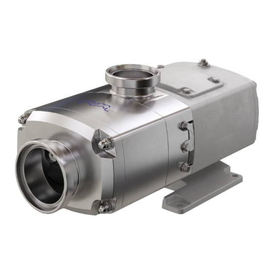
2 General description 2.1 General description The Alfa Laval OS range of pumps is of conventional Twin Screw pump design with the positive displacement being provided by non-contacting, contra rotating screws within a fully swept pump chamber. Handling from low to high viscosity pumped media, the pump’s characteristic smooth, low shear pumping action is ideal in application areas such as Dairy, Food, Beverage, Home &... -
Page 7: Safety
3 Safety Unsafe practices and other important information are emphasized in this manual. Warnings are emphasized by means of special signs. A A l l w w a a y y s s r r e e a a d d t t h h e e m m a a n n u u a a l l b b e e f f o o r r e e u u s s i i n n g g t t h h e e p p u u m m p p ! ! 3.1 Important information W W A A R R N N I I N N G G Indicates that special procedures must be followed to avoid serious personal injury. -
Page 8: Warning Signs
3 Safety Unsafe practices and other important information are emphasized in this manual. Warnings are emphasized by means of special signs. A A l l w w a a y y s s r r e e a a d d t t h h e e m m a a n n u u a a l l b b e e f f o o r r e e u u s s i i n n g g t t h h e e p p u u m m p p ! ! 3.2 Warning signs G G e e n n e e r r a a l l w w a a r r n n i i n n g g : : D D a a n n g g e e r r o o u u s s e e l l e e c c t t r r i i c c a a l l v v o o l l t t a a g g e e : :... -
Page 9: Safety Precautions
A A l l w w a a y y s s have the pump electrically connected by authorized personnel. (See the motor instruction supplied with the drive unit) Alfa Laval recommends the supply disconnecting device shall be in accordance with EN 60204-1. O O p p e e r r a a t t i i o o n n : : A A l l w w a a y y s s read the technical data thoroughly. - Page 10 3 Safety Unsafe practices and other important information are emphasized in this manual. Warnings are emphasized by means of special signs. A A l l w w a a y y s s r r e e a a d d t t h h e e m m a a n n u u a a l l b b e e f f o o r r e e u u s s i i n n g g t t h h e e p p u u m m p p ! ! T T r r a a n n s s p p o o r r t t a a t t i i o o n n : : T T r r a a n n s s p p o o r r t t a a t t i i o o n n o o f f t t h h e e p p u u m m p p o o r r t t h h e e p p u u m m p p u u n n i i t t : : N N e e v v e e r r lift or elevate in any way other than described in this manual...
-
Page 11: Recycling Information
When in doubt, or in the absence of local regulations, please contact the local Alfa Laval sales company. CONTACT CSI FOR MORE INFORMATION | CSIDESIGNS.COM | SALES@CSIDESIGNS.COM | 417.831.1411... -
Page 12: Installation
4 Installation 4.1 Unpacking, Handling and Storage S S t t e e p p 1 1 Always ensure any personnel undertaking lifting operations have the suitable experience and training to do so safely. Always ensure any lifting equipment used is in good condition and has been suitably tested, using lifting logs when applied. Always refer to the pump weights guide (Section 6) and ensure any lifting equipment used is rated for and used within the load limits. - Page 13 4 Installation S S t t e e p p 3 3 After receipt and inspection, if the pump is not to be installed immediately, the pump should be repacked in the original packaging and placed in suitable storage. The following points should be noted: - Plastic or gasket type port covers should be left in place.
-
Page 14: System Design And Installation
4 Installation To ensure optimum operation it is important that any pump unit is installed correctly. When designing a pumping system the following should be taken into consideration. 4.2 System design and installation D D e e s s i i g g n n : : - Confirm the Net Positive Suction Head (NPSH) available from the system exceeds the NPSH required by the pump, as this is crucial for ensuring the smooth operation of the pump and preventing cavitation. - Page 15 4 Installation To ensure optimum operation it is important that any pump unit is installed correctly. When designing a pumping system the following should be taken into consideration. P P u u m m p p L L u u b b r r i i c c a a t t i i o o n n : : The pump will be supplied filled with food grade oil with NSF/NSDA H1 Approval.
- Page 16 4 Installation To ensure optimum operation it is important that any pump unit is installed correctly. When designing a pumping system the following should be taken into consideration. B B a a l l l l F F o o o o t t B B a a s s e e p p l l a a t t e e w w i i t t h h A A d d j j u u s s t t a a b b l l e e F F e e e e t t The pump can be supplied with an optional ball foot baseplate with height adjustable feet.
- Page 17 4 Installation To ensure optimum operation it is important that any pump unit is installed correctly. When designing a pumping system the following should be taken into consideration. C C o o u u p p l l i i n n g g a a l l i i g g n n m m e e n n t t : : Before the pump unit is installed is it important to ensure that the mounting surface is flat to avoid distortion of the baseplate, which may cause pump/motor shaft misalignment and pump/motor unit damage.
-
Page 18: Flushing Seal Arrangement And Pre-Start Up Checks
4 Installation 4.3 Flushing seal arrangement and pre-start up checks S S t t e e p p 1 1 A flushed seal arrangement is fitted in order to cool or clean the seal area. It is important that: - The flush is correctly connected on both sides for the seals (see below). - A compatible flushing fluid is used and supplied at the correct pressure and flow rate (See below). - Page 19 4 Installation S S t t e e p p 6 6 P P r r e e - - s s t t a a r r t t u u p p c c h h e e c c k k s s - Check the pipework system has been purged to remove debris.
-
Page 20: Cleaning In Place (Cip)
Slow rotation with the shaft is possible if the pump has a single flushed seal or double shaft seal (<100 1/min). The OS twin screw pumps are only suitable for the SIP (Sterilisation In Place) method in consultation with Alfa Laval. -
Page 21: Maintenance Schedule
5 Maintenance 5.2 Maintenance schedule It is advisable to install pressure gauges on both sides of the pump so that any problems within the pump/pipework can be monitored. M M a a i i n n t t e e n n a a n n c c e e s s c c h h e e d d u u l l e e Y Y o o u u r r w w e e e e k k l l y y s s c c h h e e d d u u l l e e s s h h o o u u l l d d i i n n c c l l u u d d e e : : - Checking the seals for leakage. -
Page 22: Dismantling
5 Maintenance 5.3 Dismantling S S t t e e p p 1 1 Before disassembling the pump refer to safety precautions. See exploded view drawings (chapter 7 Parts list.) Removing pump cover and pump casing 1. Remove front cover nuts, washers, front cover, front cover elastomer and pump casing. 3205-0010 CONTACT CSI FOR MORE INFORMATION | CSIDESIGNS.COM | SALES@CSIDESIGNS.COM | 417.831.1411... - Page 23 5 Maintenance S S t t e e p p 2 2 Removing feed screws 1. Insert a plastic/wooden block between the feed screw leading edge and opposite screw to prevent from turning. 3205-0011 A) Plastic/wooden block 2. Remove feed screw nuts, feed screw nut elastomer and feed screws NOTE: the identification marking on the screws and the shafts.
- Page 24 5 Maintenance S S t t e e p p 3 3 Removing primary seal components. 1. Remove seal retaining plugs, O-rings and gland guards. 3205-0013 2. Gently ease cartridge seals from housing by levering against the gearcase and back of seal assembly if necessary. 3205-0014 S S t t e e p p 4 4 Removing seal housing...
- Page 25 5 Maintenance S S t t e e p p 5 5 Disassembling of gearbox 1. Remove pump casing studs. 2. Place a tray under the oil drain to collect the waste lubricant. 3. Remove the oil drain plug and seal and allow lubricant to drain. 4.
- Page 26 5 Maintenance S S t t e e p p 6 6 Disassembling of front gearbox 1. Remove gear top cover bolts, washers, gear top cover and gear cover O-Ring. 2. Remove lip seals. 3. Remove needle bearing snap ring. 4.
- Page 27 5 Maintenance S S t t e e p p 8 8 Disassembling of shaft assembly 1. Fix the shaft assembly in a vice fitted with soft jaws taking care not to damage the shaft assembly. 2. Bend up locking tab on washer from bearing nut. 3.
- Page 28 5 Maintenance S S t t e e p p 9 9 Removing bearing and gear 1. Mount the shaft vertically in a press (splines pointing down) with a tool positively located against the gear and apply pressure to the top of the shaft so that the shaft passes through the bearings and gear. C C A A U U T T I I O O N N 2.
- Page 29 5 Maintenance S S t t e e p p 1 1 1 1 Remove lip seal from gearbox end cover 1. Extract the lip seal from the gearbox end cover. It is essential to renew the lip seal prior to assembly. 3205-0024 CONTACT CSI FOR MORE INFORMATION | CSIDESIGNS.COM | SALES@CSIDESIGNS.COM | 417.831.1411...
-
Page 30: Assembly
5 Maintenance Take care not to damage shaft surfaces, in particular where bearings and lipseals will be located Ensure all fastenings are tightened to the torque settings as shown in Technical Data (See chapter 6 Technical data) 5.4 Assembly S S t t e e p p 1 1 Assembly of adjustable gear 1. - Page 31 5 Maintenance Take care not to damage shaft surfaces, in particular where bearings and lipseals will be located Ensure all fastenings are tightened to the torque settings as shown in Technical Data (See chapter 6 Technical data) S S t t e e p p 2 2 Fitting bearings to shaft 1.
- Page 32 5 Maintenance Take care not to damage shaft surfaces, in particular where bearings and lipseals will be located Ensure all fastenings are tightened to the torque settings as shown in Technical Data (See chapter 6 Technical data) S S t t e e p p 3 3 Install lip seal in gearbox end cover 1.
- Page 33 5 Maintenance Take care not to damage shaft surfaces, in particular where bearings and lipseals will be located Ensure all fastenings are tightened to the torque settings as shown in Technical Data (See chapter 6 Technical data) S S t t e e p p 5 5 Assembling of gearbox.
- Page 34 5 Maintenance Take care not to damage shaft surfaces, in particular where bearings and lipseals will be located Ensure all fastenings are tightened to the torque settings as shown in Technical Data (See chapter 6 Technical data) S S t t e e p p 7 7 Install seal housing.
- Page 35 5 Maintenance Take care not to damage shaft surfaces, in particular where bearings and lipseals will be located Ensure all fastenings are tightened to the torque settings as shown in Technical Data (See chapter 6 Technical data) S S t t e e p p 9 9 Fitting feed screws.
- Page 36 5 Maintenance Take care not to damage shaft surfaces, in particular where bearings and lipseals will be located Ensure all fastenings are tightened to the torque settings as shown in Technical Data (See chapter 6 Technical data) S S t t e e p p 1 1 0 0 Setting feed screw timing.
- Page 37 5 Maintenance Take care not to damage shaft surfaces, in particular where bearings and lipseals will be located Ensure all fastenings are tightened to the torque settings as shown in Technical Data (See chapter 6 Technical data) S S t t e e p p 1 1 1 1 Fitting pump casing and front cover.
- Page 38 5 Maintenance Take care not to damage shaft surfaces, in particular where bearings and lipseals will be located Ensure all fastenings are tightened to the torque settings as shown in Technical Data (See chapter 6 Technical data) S S t t e e p p 1 1 3 3 Adding lubricant 1.
-
Page 39: Maintenance Seals - Single Seal - All Models
5 Maintenance Take care not to damage shaft surfaces, in particular where bearings and lipseals will be located Ensure all fastenings are tightened to the torque settings as shown in Technical Data (See chapter 6 Technical data) 5.5 Maintenance seals - Single Seal - All Models 3205-0047 3205-0079 A A s s s s e e m m b b l l y y... - Page 40 5 Maintenance Take care not to damage shaft surfaces, in particular where bearings and lipseals will be located Ensure all fastenings are tightened to the torque settings as shown in Technical Data (See chapter 6 Technical data) S S t t e e p p 4 4 Align the slots in the rotary face (73) with the pins fitted in the rotary holder bore (71), then firmly press the rotary face (73) fully home into the rotary holder bore (71).
-
Page 41: Single Flushed Seal - All Models
5 Maintenance Take care not to damage shaft surfaces, in particular where bearings and lipseals will be located Ensure all fastenings are tightened to the torque settings as shown in Technical Data (See chapter 6 Technical data) 5.6 Single Flushed Seal - All Models 3205-0048 3205-0080 A A s s s s e e m m b b l l y y... - Page 42 5 Maintenance Take care not to damage shaft surfaces, in particular where bearings and lipseals will be located Ensure all fastenings are tightened to the torque settings as shown in Technical Data (See chapter 6 Technical data) S S t t e e p p 4 4 Align the slots in the rotary face (73) with the pins fitted in the rotary holder bore (71), then firmly press the rotary face (73) fully home into the rotary holder bore (71).
-
Page 43: Double Seal Os1X
5 Maintenance Take care not to damage shaft surfaces, in particular where bearings and lipseals will be located Ensure all fastenings are tightened to the torque settings as shown in Technical Data (See chapter 6 Technical data) 5.7 Double Seal OS1x 3205-0078 3205-0081 A A s s s s e e m m b b l l y y... - Page 44 5 Maintenance Take care not to damage shaft surfaces, in particular where bearings and lipseals will be located Ensure all fastenings are tightened to the torque settings as shown in Technical Data (See chapter 6 Technical data) S S t t e e p p 4 4 Lightly lubricate the seal housing profile elastomer (83) and fit onto the seal housing (74).
- Page 45 5 Maintenance Take care not to damage shaft surfaces, in particular where bearings and lipseals will be located Ensure all fastenings are tightened to the torque settings as shown in Technical Data (See chapter 6 Technical data) S S t t e e p p 2 2 1 1 Validate the assembly by compressing the seal a few times, making sure it springs back out each time.
-
Page 46: Double Seal Os2X, Os3X, Os4X
5 Maintenance Take care not to damage shaft surfaces, in particular where bearings and lipseals will be located Ensure all fastenings are tightened to the torque settings as shown in Technical Data (See chapter 6 Technical data) 5.8 Double Seal OS2x, OS3x, OS4x 3205-0051 3205-0082 A A s s s s e e m m b b l l y y... - Page 47 5 Maintenance Take care not to damage shaft surfaces, in particular where bearings and lipseals will be located Ensure all fastenings are tightened to the torque settings as shown in Technical Data (See chapter 6 Technical data) S S t t e e p p 4 4 Align the slots in the rotary face (73) with the pins fitted in the rotary holder bore (71), then firmly press the rotary face (73) fully home into the rotary holder bore (71).
- Page 48 5 Maintenance Take care not to damage shaft surfaces, in particular where bearings and lipseals will be located Ensure all fastenings are tightened to the torque settings as shown in Technical Data (See chapter 6 Technical data) S S t t e e p p 2 2 0 0 Validate the assembly by compressing the seal a few times, making sure it springs back out each time.
-
Page 49: Heating (Option)
H H e e a a t t i i n n g g C C o o n n n n e e c c t t i i o o n n s s S S i i z z e e OS12, OS14, OS16 G1/4” (1/4” NPT) OS22, OS24, OS26 G1/4”... -
Page 50: Rectangular Inlet (Option)
5 Maintenance Take care not to damage shaft surfaces, in particular where bearings and lipseals will be located Ensure all fastenings are tightened to the torque settings as shown in Technical Data (See chapter 6 Technical data) 5.10 Rectangular Inlet (option) 3205-0057 A) Rectangular Inlet The mating adaptor and gaskets/seals should conform to country specific hygienic regulations such as 3A. -
Page 51: Trouble Shooting
5 Maintenance Take care not to damage shaft surfaces, in particular where bearings and lipseals will be located Ensure all fastenings are tightened to the torque settings as shown in Technical Data (See chapter 6 Technical data) 5.11 Trouble shooting P P r r o o b b l l e e m m P P r r o o b b a a b b l l e e C C a a u u s s e e s s S S o o l l u u t t i i o o n n s s... -
Page 52: Technical Data
O O i i l l c c a a p p a a c c i i t t i i e e s s l l i i t t r r e e s s ( ( U U S S P P i i n n t t s s ) ) OS12 / OS14 / OS16 0.5 (1.06) OS22 / OS24 / OS26 1.0 (2.11) - Page 53 ( ( i i n n c c h h . . ) ) O O S S 1 1 x x O O S S 2 2 x x O O S S 3 3 x x O O S S 4 4 x x OS12 OS22 OS32 OS42 (0.24) (0.47)
-
Page 54: Pumphead Clearance Information
6 Technical data Take care not to damage shaft surfaces, in particular where bearings and lipseals will be located Ensure all fastenings are tightened to the torque settings as shown in Technical Data (See chapter 6 Technical data) 6.2 Pumphead Clearance information 3205-0044 3205-0043 A) Solids handling max ball diameter... -
Page 55: Parts List
7 Parts list 7.1 Twin Screw Pump Range (All Models) CONTACT CSI FOR MORE INFORMATION | CSIDESIGNS.COM | SALES@CSIDESIGNS.COM | 417.831.1411... - Page 56 7 Parts list 48,49,59 * * C C a a r r t t r r i i d d g g e e S S e e a a l l CONTACT CSI FOR MORE INFORMATION | CSIDESIGNS.COM | SALES@CSIDESIGNS.COM | 417.831.1411...
- Page 57 7 Parts list P P a a r r t t s s l l i i s s t t Pos. Denomination Auxiliary Shaft Drive Shaft Gear Key Drive Shaft Key Front Lip Seal Circlip Ball Bearing Circlip Gear Sleeve Bolts Gear Sleeve Timing Gear Drive Shaft...
- Page 58 © Alfa Laval Corporate AB This document and its contents is owned by Alfa Laval Corporate AB and protected by laws governing intellectual property and thereto related rights. It is the responsibility of the user of this document to comply with all applicable intellectual property laws. Without limiting any rights related to this document, no part of this document may be copied, reproduced or transmitted in any form or by any means (electronic, mechanical, photocopying, recording, or otherwise), or for any purpose, without the expressed permission of Alfa Laval Corporate AB.
Need help?
Do you have a question about the OS12 and is the answer not in the manual?
Questions and answers