
Subscribe to Our Youtube Channel
Related Manuals for RenewAire HE4XRTH


Summary of Contents for RenewAire HE4XRTH
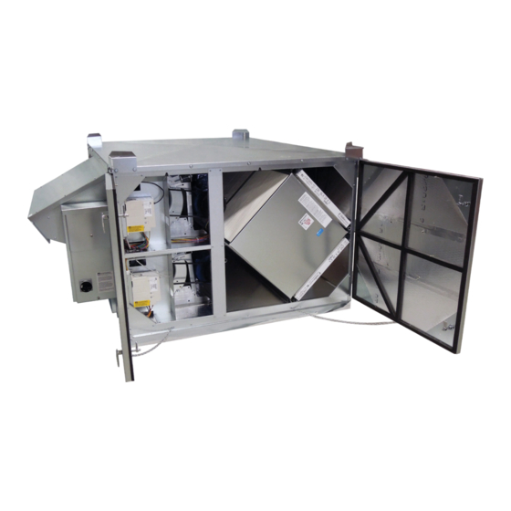
- Page 1 HE SERIES ERV Installation, Operation and Maintenance Manual HE4XRTH HE4XRTF HE4XRTR HE4XRTV HE-4XRTR Shown...
- Page 2 HE-Series Outdoor WARNING CAUTION ARC FLASH AND ELECTRIC SHOCK HAZARD RISK OF CONTACT WITH HIGH SPEED MOVING PARTS Arc flash and electric shock hazard. Disconnect all electric Disconnect all local and remote power supplies, verify with power supplies, verify with a voltmeter that electric power a voltmeter that electric power is off and all fan blades have is off and wear protective equipment per NFPA 70E before stopped rotating before working on the unit.
- Page 3 Locate the RenewAire unit label found on the outside of the unit. contractor. The completed NOTE: This information is for purposes of identifying the unit-specific option data from the document is to be turned Option Code.
-
Page 4: Table Of Contents
TABLE OF CONTENTS HE-Series Outdoor 1.0 OVERVIEW 5.5 WIRING SCHEMATICS..........20 5.6 EXTERNAL CONTROL CONNECTIONS .....22 1.1 DESCRIPTION ............7 5.6.1 Single 2-Wire Control, Unpowered ........22 1.2 AIRFLOW ..............7 5.6.2 Single 2-Wire Control, Separate Power ......22 5.6.3 Control Sending 24 VAC “ON” Signal .........22 2.0 COMPONENT DESCRIPTIONS 5.6.4 External Control Using ERV Power Supply ......22 5.6.5 Control with 2 Non-Powered Relay Contacts......23... - Page 5 TABLE OF CONTENTS HE-Series Outdoor 8.0 TROUBLESHOOTING 9.0 FACTORY ASSISTANCE TABLE OF ILLUSTRATIONS Figure 1.2.0 Airflow Orientations ......................8 Figure 2.4.0 E-Box With Motor Starters ....................9 Figure 3.2.0 HE4XRT Weights and COG ..................... 11 Figure 4.2.0 HE4XRT Service Clearance (TYP) ................... 12 Figure 5.3.0 Outside Air Hood (Typical) .....................
- Page 6 3: Voltage Codes "1" & "9" only available with Phase Code "1" (Single-Phase). 4: Voltage Codes "4" & "8" only available with Phase Code "3" (Three-Phase). 5: Voltage Code "8" (575V) not available with models HE07-, HE10-, & HE1.5. For Technical Support E-mail: RenewaireSupport@renewaire.com To Place an Order E-mail: RenewaireOrders@renewaire.com 1.800.627.4499...
-
Page 7: Overview
VFDs, a RenewAire Commercial Controller or by a BMS. There are a number of different control devices available to control the operation or speed of the unit fans. For further information on available control accessories, see the HE RenewAire catalog. -
Page 8: Component Descriptions
Return Air [RA] enters side of unit. HE4XRTF Roof Curb Supply Air [SA] exits bottom of unit. Return Air [RA] enters side of unit. HE4XRTH Equipment Rail Supply Air [SA] exits side of unit. FIGURE 1.2.0 AIRFLOW ORIENTATIONS 2.0 COMPONENT DESCRIPTIONS 2.1 CABINET... -
Page 9: Enthalpic Cores
All HE4XRT units come equipped with eight MERV 8 20" x 20" x 2" (nominal) pleated filters. MERV 13 filters can be ordered as an accessory and are shipped loose. (8) 20" x 20" x 2" (nominal) pleated filters. Actual size: 19.5" x 19.5" x 1.75" www.renewaire.com (800) 627- 4499 support@renewaire.com Minimum recommended effectiveness: MERV 6. -
Page 10: Factory Installed Options
Any discovered shipping damage should be immediately reported to the RenewAire sales rep and the damage must be recorded on the Bill Of Lading, prior to signing for acceptance of the shipment. -
Page 11: Rigging And Center Of Gravity
Upon receipt of the HE4XRT, inspect the unit for obvious external damage. If damage is observed, take digital pictures and report the damage to your RenewAire rep. Note the damage on the carrier’s Bill of Lading. Depending on expected transport and storage conditions, the unit may have only the duct openings covered, it may be stretch-wrapped or it may be crated. -
Page 12: Unit Placement
The HE4XRT is designed for installation outdoors, typically on a roof top. The preferred mounting method is to place the ERV on an optional manufactured curb, designed for the specific unit. RenewAire recommends the use of optional curb clips to provide substantial resistance to wind damage. -
Page 13: Sound Attenuation
UNIT PLACEMENT HE-Series Outdoor 4.3 SOUND ATTENUATION Take these simple steps to attenuate noise from the unit. 4.3.1 Outside the Building Exhaust velocity noise is the primary cause of unit-related noise outside the building. Size the exhaust duct and grille for less than 1000 FPM air velocity. When practical, orient the exhaust air hood to point away from houses or public areas. -
Page 14: Installation
(provided) on all bearing surfaces on the curb. Optional installation on owner-provided rails (HE4XRTH only): RenewAire recommends that all HE4XRT units be installed on a RenewAire-supplied curb that is manufactured to match individual units. The only unit that may be installed on owner-supplied mountings rails is the HE4XRTH. -
Page 15: Duct Insulation
FLANGE LOCATIONS OA HOOD (TYPICAL) FIGURE 5.3.0 OUTSIDE AIR SCREW LOCATIONS OA Hood Screw Loca�ons www.renewaire.com (800) 627- 4499 support@renewaire.com Remove and save the screws in the roof panel overhang above the OA hood. FIGURE 5.3.1 OUTSIDE AIR HOOD (TYPICAL) OA Hood Installa�on... -
Page 16: Exhaust Air Hood
LOCATIONS FLANGE EA HOOD (TYP) FIGURE 5.3.2 EXHAUST AIR SCREW LOCATIONS www.renewaire.com (800) 627- 4499 support@renewaire.com EA Hood Screw Loca�ons Remove and save the screws in the roof panel overhang above the EA hood. FIGURE 5.3.3 EXHAUST AIR HOOD (TYPICAL) Slip the top flange of the EA hood assembly under the roof panel overhang to flash the hood assembly from precipitation. - Page 17 INSTALLATION HE-Series Outdoor T H I S P A G E I S I N T E N T I O N A L LY L E F T B L A N K . 1.800.627.4499...
-
Page 18: Electrical Requirements
Contactors. Without this inter-connection the motor(s) will not be protected against overload. HIGH-VOLTAGE SUPPLY WIRING IS TERMINATED ON THE TOP OF THE DISCONNECT SWITCH HIGH-VOLTAGE SUPPLY LOW-VOLTAGE CONTROL WIRING ENTRY WIRING ENTRY FIGURE 5.4.0 E-BOX WIRING ENTRY POINTS www.renewaire.com (800) 627- 4499 support@renewaire.com 1.800.627.4499... -
Page 19: Low Voltage Control System
INSTALLATION HE-Series Outdoor 5.4.2 Low Voltage Control System NOTICE This ERV is provided with a Class II 24 VAC power supply system that operates the unit’s If primary-side voltage contactor(s) for HE4XRT. The ERV’s 24 VAC Power Supply can also be used to power the is 230 VAC, move black externally-installed controls system: up to 8VA of power is available. -
Page 20: Wiring Schematics
INSTALLATION HE-Series Outdoor 5.5 WIRING SCHEMATICS FIGURE 5.5.0 GENERIC SINGLE-PHASE WIRING SCHEMATIC 1.800.627.4499... -
Page 21: Figure 5.5.1 Generic Three-Phase Wiring Schematic
INSTALLATION HE-Series Outdoor FIGURE 5.5.1 GENERIC THREE-PHASE WIRING SCHEMATIC 1.800.627.4499... -
Page 22: External Control Connections
INSTALLATION HE-Series Outdoor 5.6 EXTERNAL CONTROL CONNECTIONS NOTE: The sim- 5.6.1 Single 2-Wire Control, Unpowered plified schematics See Figure 5.6.0 if the control requires no power from the ERV and acts as a simple ON/OFF below show only switch. The control must not supply any power to the ERV. the relevant portions of Install jumper (provided) between terminals 2 and 3. -
Page 23: Control With 2 Non-Powered Relay Contacts
INSTALLATION HE-Series Outdoor AN EXTERNAL CONTROL USING UNIT'S UNIT INTERNAL CONTROL WIRING 24VAC POWER SUPPLY (SIMPLIFIED) 24VAC Available at Terminals 1 & 2 Unit's 24VAC Power Supply Connect Terminals 2 & 3 Isolation Relay Coil (Fresh Air) Isolation Relay Coil (Exhaust Air) Connect Terminals 4 &... -
Page 24: Quick-Start For Testing Correct 3Ph Wiring
OPERATION HE-Series Outdoor 5.7 QUICK-START FOR TESTING CORRECT 3PH WIRING NOTE: Any changes All units that run on 3 phase power should be test-run immediately after high voltage wiring to unit low-voltage connections are made. This will verify that the three phases are properly connected, that the wiring should be dampers will open and close properly and the fans are working properly. -
Page 25: Unit Startup
OPERATION HE-Series Outdoor 6.3 UNIT STARTUP 6.3.1 Fixed-Speed Units Most fixed-speed units do not have any external controlling signals and only require turning on the disconnect switch, located on the E-Box. When the disconnect switch is turned ON, any dampers will first move into their correct operating positions and then power is suppled to the motor contactors, causing the fans to run. -
Page 26: All Fixed-Speed Units
0.60 0.70 0.80 The proper operating air- 1450 2030 2600 3180 3760 4340 4910 Supply Air (SA) www.renewaire.com (800) 627- 4499 support@renewaire.com flow range for this model is Return Air (RA) 1370 1900 2430 3480 4020 4550 1000–4400 CFM. 1.800.627.4499... -
Page 27: Filter Pressure Drop
OPERATION HE-Series Outdoor Initial Pressure Drop of MERV 8 Filters 6.4.2 Filter Pressure Drop supplied with this unit NOTE: Clean filter pressure drop is included in unit air- (4)20x20x2 MERV 13 (IOM) flow performance tables. 1000 1500 2000 2500 3000 3500 4000 Unit Airflow (CFM) Initial Pressure Drop of MERV 13 Filters FIGURE 6.4.1 INITIAL PRESSURE DROP OF MERV 8 FILTERS, SUPPLIED WITH THIS UNIT... -
Page 28: Sheave Adjustment
OPERATION HE-Series Outdoor 6.4.3 Sheave Adjustment All fan motors that are not controlled by a VFD are equipped with an adjustable sheave. These adjustable sheaves must be re-set in the field to attain optimum performance of the ERV. This adjustment is to be done after all ductwork is connected. Adjustable sheaves are held in position on the drive motor shaft by a set screw that is normally hidden until the belt(s) is removed. -
Page 29: Unit Maintenance
7.0 UNIT MAINTENANCE WARNING Danger of injury if unit RenewAire ERVs are built to operate with minimal maintenance. After unit commissioning, the starts unexpectedly. primary areas of attention are the air filters, periodic lubrication of the fan motors and annual Switch power off at service vacuuming of the enthalpic cores.. -
Page 30: Belt Tension
NOTE: Each motor 7.5.3 Motor Cleanliness manufacturer spec- ifies the frequency Removing dust and grease buildup on the motor housing assists proper cooling. Never wash- www.renewaire.com (800) 627- 4499 support@renewaire.com of maintenance and the down the motor with high pressure spray. -
Page 31: Enthalpic Cores
MAINTENANCE HE-Series Outdoor 7.6 ENTHALPIC CORES CAUTION Risk of DAMAGE TO ENTHALPIC CORES Whenever working within the ERV cabinet, protect the enthalpic cores from accidental damage. The core media is subject to damage from dropped tools or other foreign objects. 7.6.1 Enthalpic Core Maintenance The enthalpic core media is a fibrous material that must be kept clean at all times. -
Page 32: Maintenance Records
MAINTENANCE HE-Series Outdoor 7.7 MAINTENANCE RECORDS MAINTENANCE LOG ENTER DATES OF SERVICE OA FILTER RA FILTER INSPECTION/ CLEAN CLEAN INITIALS CHANGE CHANGE CLEANING CORE BLOWERS 1.800.627.4499... - Page 33 MAINTENANCE HE-Series Outdoor MISCELLANEOUS SERVICE NOTES DATE SERVICE INITIALS 1.800.627.4499...
-
Page 34: Service Parts
MAINTENANCE HE-Series Outdoor 7.8 SERVICE PARTS FIGURE 7.8.0 HE4XRT SERVICE PARTS 1.800.627.4499... - Page 35 TROUBLESHOOTING HE-Series Outdoor 8.0 TROUBLESHOOTING If problems occur with a RenewAire ERV, the primary resources for trouble-shooting are the unit as-built wiring schematics and the Sequence Of Operation (SOO) for each control scheme. 9.0 FACTORY ASSISTANCE In the unlikely event that you need assistance from the factory for a specific issue, make sure that you have the information called for in the Unit Records page in the Owner Information section of this manual.
- Page 36 About RenewAire For over 40 years, RenewAire has been a pioneer in enhancing indoor air quality (IAQ) in commercial and residential buildings of every size. This is achieved while maximizing sustainability through our fifth-generation, static-plate, enthalpic-core Energy Recovery Ventilators (ERVs) that optimize energy efficiency, lower capital costs via load reduction and decrease operational expenses by minimizing equipment needs, resulting in significant energy savings.
Need help?
Do you have a question about the HE4XRTH and is the answer not in the manual?
Questions and answers