Advertisement
Quick Links
45 Tones 3 stage Alarm Horn Sounder / 5 Joule
Beacon
Automatic Synchronisation (sounder)
Volume control
Type 4 / 4X / 13
Operating Temperature Range
-20ºC to +55ºC
Unit Type No.
E2xCS112-5UL
Input Voltages: DC Units
AC Units
Max. Operating Temperature / Code at +55º Ambient
Hazardous Location
Class I, Division 2, Groups A, B, C, D
Class II, Division 2, Groups F and G
Class III, Divisions 1 and 2
Max. Operating Temperature / Code at +40º Ambient
Hazardous Location
Class I, Division 2, Groups A, B, C, D
The equipment is suitable for use in the hazardous locations
listed above or non-hazardous locations only.
PRE-INSTALLATION
WARNING -
Before the E2xCS112-5UL combined sounder /
beacon is installed the required tone and output volume must
be set. Note the units are factory set to tone 2 (800/1000Hz
alternating at 2Hz) and maximum output. If necessary the unit
should be connected to a suitable power supply in a safe area
to determine what tone pattern and output level is required.
M4 Hex
Socket Screw
Spring Washer
Flat Washer
WARNING – NOT TO BE USED AS A VISUAL PUBLIC
MODE NOTIFICATION APPLIANCE
WARNING – HIGH VOLTAGE SHOCK HAZARD.
WAIT 5 MINUTES AFTER REMOVING
POWER BEFORE OPENING THE
ENCLOSURE
__________________________________________________________________________________________________________________
European Safety Systems Ltd. Impress House, Mansell Road, Acton, London W3 7QH
Document No. IS4209
Issue: H
INSTRUCTION & SERVICE MANUAL
For Use In Hazardous Locations
7KA1
12V or 24V or 48V
120V or 230V 50/60Hz
Temperature Code
T2D (215ºC)
T6 (85ºC)
T6 (85ºC)
Temperature Code
T3 (200ºC)
26-03-13
Sheet 1 of 3
E2xCS112-5UL COMBINED
ALARM HORN SOUNDER / BEACON
E2xCS112-05UL DC Sounder Section
Tone Switch and Volume
Control Positions
Tone Selection
DIP Switch
Volume Control
Potentiometer
48V Version
Volume Control
Potentiometer
12V & 24V Versions
E2xCS112-05UL AC Sounder Section
Tone Switch and Volume
Control Positions
Tone Selection
DIP Switch
Volume Control
Potentiometer
WARNING - EXPLOSION HAZARD - SUBSTITUTION OF
COMPONENTS MAY IMPAIR SUITABILITY
FOR CLASS I, II DIVISION 2.
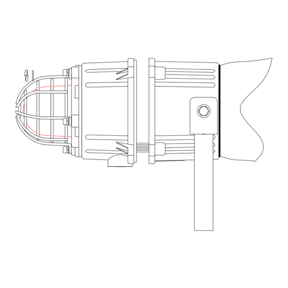
MOUNTING
The E2xCS112-5UL combined sounder / beacon must be
mounted using the rotating bracket as shown. If the cover has
been removed to set the tone or volume control ensure that it
has been correctly replace before the sounder is mounted.
WIRING INSTALLATION
The E2xCS112-5UL combined sounder /beacon is provided with
2 off M20 x 1.5 cable entries.
1 x ½" NPT adaptor and 1 x M20 stopping plug are provided.
Installation using Field Wiring Leads and Conduit
If the sounder is supplied pre-wired with flying leads, these are
colour coded and should be connected as shown in the diagram
below.
The conduit running from the supply to the sounder must
include an equipment grounding conductor that is at earth
sales@e2s.com
www.e2s.com
E E
N N
L L
18° Increments
Release nut to rotate
bracket.
Tel: +44 (0)20 8743 8880
Fax: +44 (0)20 8740 4200
Advertisement

Related Manuals for E2S E2xCS112-5UL COMBINED


Summary of Contents for E2S E2xCS112-5UL COMBINED
- Page 1 FOR CLASS I, II DIVISION 2. The equipment is suitable for use in the hazardous locations listed above or non-hazardous locations only. MOUNTING The E2xCS112-5UL combined sounder / beacon must be PRE-INSTALLATION mounted using the rotating bracket as shown. If the cover has WARNING -...
-
Page 2: Power Supply Selection
Black (S) and White (S) wires must be maintained for 2 Green/Yellow (B) Ground and 3 stages. __________________________________________________________________________________________________________________ European Safety Systems Ltd. Impress House, Mansell Road, Acton, London W3 7QH sales@e2s.com Tel: +44 (0)20 8743 8880 www.e2s.com Fax: +44 (0)20 8740 4200 Document No. IS4209 Issue: H... -
Page 3: Volume Control
All DC combined units have a blocking diode fitted in the supply input lines to both the sounder and the beacon. An __________________________________________________________________________________________________________________ European Safety Systems Ltd. Impress House, Mansell Road, Acton, London W3 7QH sales@e2s.com Tel: +44 (0)20 8743 8880 www.e2s.com Fax: +44 (0)20 8740 4200 Document No. - Page 4 __________________________________________________________________________________________________________________ European Safety Systems Ltd. Impress House, Mansell Road, Acton, London W3 7QH sales@e2s.com Tel: +44 (0)20 8743 8880 www.e2s.com Fax: +44 (0)20 8740 4200 Document No. IS4209-ATEX...
- Page 5 Electrostatic charging hazard - Clean only with a damp cloth __________________________________________________________________________________________________________________ European Safety Systems Ltd. Impress House, Mansell Road, Acton, London W3 7QH sales@e2s.com Tel: +44 (0)20 8743 8880 www.e2s.com Fax: +44 (0)20 8740 4200 Document No.
- Page 6 This Declaration is issued under the sole responsibility of the manufacturer. Martin Streetz Document No.: DC-062_Issue_A Quality Assurance Manager Date and Place of Issue: London, 02/03/2015 E2S Telephone: +44 (0)20 8743 8880 Fax: +44 (0)20 8740 4200 Email: sales@e2s.com www.e2s.com QAF_252_Issue_2...
Need help?
Do you have a question about the E2xCS112-5UL COMBINED and is the answer not in the manual?
Questions and answers