
Related Manuals for Grindex Bravo 500


Summary of Contents for Grindex Bravo 500
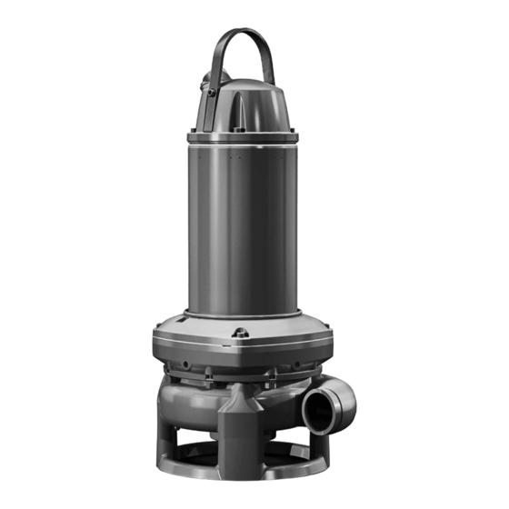
- Page 1 Installation, Operation, and Maintenance manual 8149.020/.190 Bravo 500...
-
Page 3: Table Of Contents
4.2.5 Connect the motor cable to the starter and monitoring equipment... 23 4.2.6 Cable charts................24 4.2.7 Sensor connection..............29 4.3 Check the impeller rotation.............. 30 5 Operation.......................... 31 5.1 Precautions..................31 5.2 Start the pump................31 8149.020/.190 Bravo 500 Installation, Operation, and Maintenance manual... - Page 4 7.4 The pump starts-stops-starts in rapid sequence........50 7.5 The pump runs but the motor protection trips........50 7.6 The pump delivers too little or no water..........51 8 Technical Reference......................53 8.1 Application limits................53 8.2 Motor data..................53 8149.020/.190 Bravo 500 Installation, Operation, and Maintenance manual...
-
Page 5: Introduction And Safety
This includes any modification to the equipment or use of parts not provided by Grindex. If there is a question regarding the intended use of the equipment, please contact a Grindex representative before proceeding. -
Page 6: User Safety
• Any maintenance for Ex-approved products must conform to international and national standards (for example, IEC/EN 60079-17). Grindex disclaims all responsibility for work done by untrained and unauthorized personnel. Product and product handling requirements These are the product and product handling requirements for Ex-approved products in potentially explosive atmospheres: •... -
Page 7: Special Hazards
Guidelines for compliance Compliance is fulfilled only when you operate the unit within its intended use. Do not change the conditions of the service without the approval of a Grindex representative. When you install or maintain explosion proof products, always comply with the directive and applicable standards (for example, IEC/EN 60079–... -
Page 8: Biological Hazards
Do NOT send the product to Xylem if it has been exposed to nuclear radiation, unless Xylem has been informed and appropriate actions have been agreed upon. 1.7 End-of-life product disposal Handle and dispose of all waste in compliance with local laws and regulations. 8149.020/.190 Bravo 500 Installation, Operation, and Maintenance manual... -
Page 9: Spare Parts
Only use the manufacturer’s original spare parts to replace any worn or faulty components. The use of unsuitable spare parts may cause malfunctions, damage, and injuries as well as void the warranty. 1.9 Warranty For information about warranty, see the sales contract. 8149.020/.190 Bravo 500 Installation, Operation, and Maintenance manual... -
Page 10: Transportation And Storage
Always lift the unit by its designated lifting points. Use suitable lifting equipment and ensure that the product is properly harnessed. Wear personal protective equipment. Stay clear of cables and suspended loads. 8149.020/.190 Bravo 500 Installation, Operation, and Maintenance manual... -
Page 11: Temperature Ranges For Transportation, Handling And Storage
Lifting equipment is always required when handling the unit. It must fulfill the following requirements: • The minimum height (contact Grindex for information) between the lifting hook and the floor must be sufficient to lift the unit. • The lifting equipment must be able to hoist the unit straight up and down, preferably without the need for resetting the lifting hook. -
Page 12: Storage Guidelines
• Before operating the unit after storage, it must be inspected. Special attention must be given to the seals and the cable entry. • The impeller or propeller must be rotated every other month to prevent the seals from sticking together. 8149.020/.190 Bravo 500 Installation, Operation, and Maintenance manual... -
Page 13: Product Description
• Modifications to the unit or installation should only be carried out after consulting with Grindex. • Original spare parts and accessories authorized by Grindex are essential for compliance. The use of other parts can invalidate any claims for warranty or compensation. -
Page 14: Parts
The impeller is a shrouded three-channel H-impeller. Mechanical seals One inner and one outer seal in a combination of materials: • Tungsten carbide • Silicon carbide RSiC • Aluminium oxide Al • Corrosion-resistant cemented carbide WCCR 8149.020/.190 Bravo 500 Installation, Operation, and Maintenance manual... -
Page 15: Sensors And Monitoring Equipment
Optional sensors Thermistor Thermistors are optional sensors for measuring the temperature. They are connected in series in the stator and activate the alarm at overtemperature. Thermistors are not applicable to Ex-approved pumps. 8149.020/.190 Bravo 500 Installation, Operation, and Maintenance manual... -
Page 16: The Data Plate
16.Direction of the impeller rotation 17.Maximum head 18.Serial number The first two characters describe the production year. 19.Rated voltage 20.Pump model 21.UKCA marking This is the data plate for non explosion-proof version .020: WS011380C 8149.020/.190 Bravo 500 Installation, Operation, and Maintenance manual... -
Page 17: Motor Regulation
• ATEX Directive • EN IEC 60079-0:2018, EN 60079-1:2014, EN ISO 80079-36:2016, EN ISO 80079-37:2016 • II 2 G Ex db h IIB T3 Gb • I M2 Ex db h I Mb 8149.020/.190 Bravo 500 Installation, Operation, and Maintenance manual... - Page 18 14.ATEX marking WS003972C 15.Country of origin FM approval plate This illustration describes the FM approval plate and the information that is contained in its fields. 1. Temperature class 2. Maximum ambient temperature WS003973A 8149.020/.190 Bravo 500 Installation, Operation, and Maintenance manual...
- Page 19 5. Stall time 6. Starting current or Rated current 7. Duty class 8. Duty factor 9. Input power 10.Rated speed 11.Additional information 12.Maximum ambient temperature 13.Serial number 14.UKEx marking WS013146A 15.Country of origin 8149.020/.190 Bravo 500 Installation, Operation, and Maintenance manual...
-
Page 20: Installation
• Always check the impeller rotation before lowering the pump into the pumped liquid. NOTICE: Do not run the pump dry. NOTICE: Never force piping to make a connection with a pump. 8149.020/.190 Bravo 500 Installation, Operation, and Maintenance manual... -
Page 21: Make The Electrical Connections
These general requirements apply for the electrical installation: • If the pump will be connected to the public mains, then the supply authority must be notified before installing the pump. When the pump is connected to 8149.020/.190 Bravo 500 Installation, Operation, and Maintenance manual... - Page 22 European CE and EMC requirements. For more information, contact a sales or authorized service representative. • For SUBCAB ™ cables, the twisted pair copper foil must be trimmed. • All unused conductors must be insulated. 8149.020/.190 Bravo 500 Installation, Operation, and Maintenance manual...
-
Page 23: Grounding (Earthing)
Peel the insulation jacket or plastic jacket. b) Peel the aluminum and textile layers. The aluminum foil is a conductive screen. Do not peel more than necessary, and remove the peeled foil. 8149.020/.190 Bravo 500 Installation, Operation, and Maintenance manual... -
Page 24: Connect The Motor Cable To The Pump
4.2.4 Connect the motor cable to the pump NOTICE: Leakage into the electrical parts can cause damaged equipment or a blown fuse. Keep the end of the motor cable dry at all times. 8149.020/.190 Bravo 500 Installation, Operation, and Maintenance manual... -
Page 25: Connect The Motor Cable To The Starter And Monitoring Equipment
If the product is rated explosion- proof or intrinsically-safe, then see the specific explosion-proof information in the safety chapter before taking any further actions. 8149.020/.190 Bravo 500 Installation, Operation, and Maintenance manual... -
Page 26: Cable Charts
T1 T2 Figure 4: Phase sequence Connection locations The figures in this section illustrate how to interpret the connection strip symbols. 8149.020/.190 Bravo 500 Installation, Operation, and Maintenance manual... - Page 27 7. FLS 10 8. CLS 9. Thermistor 10.Level sensor 11.Capacitor 12.Crimp connection 13.Crimp isolation 14.Current transformer FLS 10 Color code standard Code Description Brown Black White Orange Green GNYE Green-Yellow Grey Blue Yellow 8149.020/.190 Bravo 500 Installation, Operation, and Maintenance manual...
- Page 28 Screen (WH) 51 680 01 Terminal clamps 6 stator leads U1 W2 V1 U2 W1 V2 6-leads connection For 8149, only the one-cable diagram applies. For 8150, only the one-cable diagram applies. 8149.020/.190 Bravo 500 Installation, Operation, and Maintenance manual...
- Page 29 U1W2 V1 U2 W1V2 Two cables One cable L2:1 L3:1 L1:1 L2:2 L3:2 L1:2 Figure 5: One cable (left) and two cables (right) 9-leads connection For 8149, only the one-cable diagram applies. 8149.020/.190 Bravo 500 Installation, Operation, and Maintenance manual...
- Page 30 Cable without separate ground conductor. Screen as ground conductor. Screened SUBCAB & FGB Screened Cable without sep. ground conductor Screen as ground conductor GN/YE shrink hose FGB Screened Mini CAS Mini CAS+AUX Figure 7: Screened SUBCAB and FGB screened 8149.020/.190 Bravo 500 Installation, Operation, and Maintenance manual...
-
Page 31: Sensor Connection
T1 Control leads WH/YE WH/YE Mini Mini T1/*OG/1 T1/*OG/1 T2/*BU/2 T2/*BU/2 WH/YE WH/YE **T3 **T3 **T4 **T4 *SUBCAB AWG *SUBCAB AWG *Screened SUBCAB *Screened SUBCAB ∞ Ohm Overtemperature 1200 Ohm 430 Ohm Leakage 8149.020/.190 Bravo 500 Installation, Operation, and Maintenance manual... -
Page 32: Check The Impeller Rotation
The correct direction of impeller rotation is clockwise when you look at the pump from above. 4. If the impeller rotates in the wrong direction, then transpose two phase leads (3-phase) and do this procedure again. 8149.020/.190 Bravo 500 Installation, Operation, and Maintenance manual... -
Page 33: Operation
The starting jerk can be powerful. Make sure nobody is close to the unit when it is started. CAUTION: Thermal Hazard The surfaces or parts of the unit may become hot during operation. Allow surfaces to cool before starting work, or wear heat-protective clothing. 8149.020/.190 Bravo 500 Installation, Operation, and Maintenance manual... - Page 34 Never put your hand into the pump housing. 3. Conduct insulation test phase to ground. To pass, the value must exceed 5 megaohms. 4. Check that the monitoring equipment works. 5. Start the pump. 8149.020/.190 Bravo 500 Installation, Operation, and Maintenance manual...
-
Page 35: Maintenance
During the maintenance and before reassembly, always remember to perform these tasks: • Clean all parts thoroughly, particularly O-ring grooves. • Change all O-rings, gaskets, and seal washers. • Lubricate all springs, screws, O-rings with grease. 8149.020/.190 Bravo 500 Installation, Operation, and Maintenance manual... -
Page 36: Torque Values
2.7 (2.0) (8.1) (16.2) Hexagon screws with countersunk heads For hexagon socket head screws with countersunk head, maximum torque for all property classes must be 80% of the values for property class 8.8. 8149.020/.190 Bravo 500 Installation, Operation, and Maintenance manual... -
Page 37: Change The Coolant
Air inside the chamber may cause parts or liquid to be propelled with force. Be careful when opening. Allow the chamber to de-pressurize before removal of the plug. 1. Empty the coolant in the inspection chamber: a) Remove the inspection plug. 8149.020/.190 Bravo 500 Installation, Operation, and Maintenance manual... - Page 38 Air inside the chamber may cause parts or liquid to be propelled with force. Be careful when opening. Allow the chamber to de-pressurize before removal of the plug. b) Use a pump to remove the coolant. 8149.020/.190 Bravo 500 Installation, Operation, and Maintenance manual...
- Page 39 Put the pump horizontally, so that one of the coolant plugs is at the lowest point of the pump. It is important that the coolant drains completely. b) Put a container under the pump. c) Remove the coolant plugs and empty the coolant. 8149.020/.190 Bravo 500 Installation, Operation, and Maintenance manual...
-
Page 40: Fill With Coolant
If DOWCAL 200 ™ from Dow Chemical Company is not available, then contact your local Grindex representative. The monopropylene glycol must fulfill the Grindex material standard M0800.82.0002. NOTICE: Deionized or distilled water must be used in the water-glycol mixture. -
Page 41: Replace The Impeller
Required tools: • 17 mm hexagon bit adapter with an extension of at least 125 mm (4.92 in.) • Impeller puller If applicable, contact your local Grindex representative for correct type and size. • Chain • Rod (wooden or copper) for locking the impeller in place, if applicable. -
Page 42: Remove The Impeller
Remove the chain from the impeller and pump housing. b) Raise the pump. c) Remove the pump housing screws. d) Remove the drive unit from the pump housing. e) Remove the O-rings. 8149.020/.190 Bravo 500 Installation, Operation, and Maintenance manual... - Page 43 Prevent the wearing cover from falling off when removing the impeller by attaching a round sling. WS002414A 5. Remove the impeller: a) Remove the impeller screw. b) Remove the impeller and the conical sleeve. WS002431A c) Remove the wearing cover. WS002411A 8149.020/.190 Bravo 500 Installation, Operation, and Maintenance manual...
-
Page 44: Install The Impeller
Fit the washer and impeller screw onto the shaft. f) Hand-tighten the impeller screw to prevent it from falling off. g) Remove the sling and fit new O-rings to the wearing cover. 8149.020/.190 Bravo 500 Installation, Operation, and Maintenance manual... - Page 45 Remove the chain from the impeller and pump housing. 7. Check that the impeller can rotate freely. The clearance between the impeller and the pump housing should be 0.1–0.7 mm (0.004–0.03 in). 8149.020/.190 Bravo 500 Installation, Operation, and Maintenance manual...
-
Page 46: Replace The Agitator
This causes the head of the propeller screw to press the propeller outward. 6. Remove the strainer, if any. 7. Remove the propeller shaft. 8. Remove the impeller screw, the barrel nut, and the parallel key. 8149.020/.190 Bravo 500 Installation, Operation, and Maintenance manual... -
Page 47: Install The Agitator Unit
It includes replacement of years, whichever comes key components and the measures first. taken during an inspection. These intervals apply to normal applications and operating conditions at media (liquid) temperatures <40°C. 8149.020/.190 Bravo 500 Installation, Operation, and Maintenance manual... -
Page 48: Inspection
1. Fill with new coolant, if necessary. Applicable for Ex-version. 2. Check that the freezing point is lower than -13°C (9°F). Terminal board Check that the connections are properly secured. Thermal contacts Normally closed circuit; interval 0–1 ohm. 8149.020/.190 Bravo 500 Installation, Operation, and Maintenance manual... -
Page 49: Overhaul
2. Change the mechanical seal unit. 3. Replace with new coolant. The thermistor/Thermal 1. Check the coolant level. contact 2. Check the start and stop levels. The overload protection Check that the impeller can rotate freely. 8149.020/.190 Bravo 500 Installation, Operation, and Maintenance manual... -
Page 50: Troubleshooting
• All connections are intact. • The relay and contactor coils are intact. • The control switch (Man/Auto) makes contact in both positions. Check the control circuit and functions. 8149.020/.190 Bravo 500 Installation, Operation, and Maintenance manual... -
Page 51: The Pump Does Not Stop When A Level Sensor Is Used
• Check the contactor and the control circuit. • Replace all defective items. The stop level is set too Raise the stop level. low. If the problem persists, then contact a sales or authorized service representative. 8149.020/.190 Bravo 500 Installation, Operation, and Maintenance manual... -
Page 52: The Pump Starts-Stops-Starts In Rapid Sequence
• Check that the impeller is correctly trimmed. The drive unit cannot • Check the fuses. Replace fuses that have tripped. receive full voltage on all • If the fuses are intact, then notify a certified three phases. electrician. 8149.020/.190 Bravo 500 Installation, Operation, and Maintenance manual... -
Page 53: The Pump Delivers Too Little Or No Water
• Replace the valves, if necessary. • Check that all valves are correctly installed according to media flow. • Check that all valves open correctly. 8149.020/.190 Bravo 500 Installation, Operation, and Maintenance manual... - Page 54 If the problem persists, then contact a sales or authorized service representative. Always state the product number and the serial number of the pump, see Product Description on page 11. 8149.020/.190 Bravo 500 Installation, Operation, and Maintenance manual...
-
Page 55: Technical Reference
Voltage variation ±10%, if it does not run continuously at full load without overheating Voltage imbalance tolerance Stator insulation H (180°C [356°F]) class Motor encapsulation Motor encapsulation is in accordance with IP68. 8149.020/.190 Bravo 500 Installation, Operation, and Maintenance manual... - Page 56 Services AB 556782-9253 361 80 Emmaboda The original instruction is in English. All non-English www.grindex.com instructions are translations of the original instruction. Sweden Tel: +46-471-24 70 00 © 2011 Grindex Fax: +46-471-24 74 01 http://tpi.xyleminc.com 899398_14.0_en-US_2022-10_IOM_8149.020/.190 Bravo 500...
Need help?
Do you have a question about the Bravo 500 and is the answer not in the manual?
Questions and answers