
Related Manuals for Grindex Bravo 900 8153.190


Summary of Contents for Grindex Bravo 900 8153.190
- Page 1 Revision 8.0 Installation, Operation, and Maintenance Manual 8153.020/.190 Bravo 900...
-
Page 3: Table Of Contents
Table of Contents Table of Contents 1 Introduction and Safety..................... 3 1.1 Introduction..................3 1.2 Safety terminology and symbols............3 1.3 User safety..................4 1.4 Ex-approved products............... 4 1.5 Special hazards................5 1.6 Protecting the environment..............6 1.7 Spare parts..................7 1.8 Warranty..................7 2 Transportation and Storage....................8 2.1 Inspect the delivery................ - Page 4 Table of Contents 6.4.1 Remove the agitator unit............43 6.4.2 Install the agitator unit.............. 44 6.5 Service the pump................44 6.5.1 Inspection................45 6.5.2 Major overhaul................. 46 6.5.3 Service in case of alarm............. 46 7 Troubleshooting....................... 47 7.1 The pump does not start..............47 7.2 The pump does not stop when a level sensor is used......
-
Page 5: Introduction And Safety
This includes any modification to the equipment or use of parts not provided by Grindex. If there is a question regarding the intended use of the equipment, please contact a Grindex representative before proceeding. -
Page 6: User Safety
• Any maintenance for Ex-approved products must conform to international and national standards (for example, IEC/EN 60079-17). Grindex disclaims all responsibility for work done by untrained and unauthorized personnel. Product and product handling requirements These are the product and product handling requirements for Ex-approved products in potentially explosive atmospheres: 8153.020/.190 Bravo 900 Installation, Operation, and Maintenance Manual... -
Page 7: Special Hazards
Guidelines for compliance Compliance is fulfilled only when you operate the unit within its intended use. Do not change the conditions of the service without the approval of a Grindex representative. When you install or maintain explosion proof products, always comply with the directive and applicable standards (for example, IEC/EN 60079–... -
Page 8: Protecting The Environment
1 Introduction and Safety result in insulation breaks, short-circuits, and exposed wires. To maximize safety when using the unit in rugged applications, the following conditions must be met: • If electrical cables must be located such that they are at risk of being run over by heavy equipment, then provide mechanical protection to prevent physical damage to the cables. -
Page 9: Spare Parts
1 Introduction and Safety 1.7 Spare parts CAUTION: Only use the manufacturer’s original spare parts to replace any worn or faulty components. The use of unsuitable spare parts may cause malfunctions, damage, and injuries as well as void the warranty. 1.8 Warranty For information about warranty, see the sales contract. -
Page 10: Transportation And Storage
Lifting equipment is always required when handling the unit. It must fulfill the following requirements: • The minimum height (contact Grindex for information) between the lifting hook and the floor must be sufficient to lift the unit. • The lifting equipment must be able to hoist the unit straight up and down, preferably without the need for resetting the lifting hook. -
Page 11: Temperature Ranges For Transportation, Handling And Storage
2 Transportation and Storage • The lifting equipment must be securely anchored and in good condition. • The lifting equipment must support weight of the entire assembly and must only be used by authorized personnel. • Two sets of lifting equipment must be used to lift the unit for repair work. •... - Page 12 2 Transportation and Storage NOTICE: Protect the product against humidity, heat sources, and mechanical damage. NOTICE: Do not place heavy weights on the packed product. Long-term storage If the unit is stored more than six months, then the following apply: •...
-
Page 13: Product Description
• Modifications to the unit or installation should only be carried out after consulting with Grindex. • Original spare parts and accessories authorized by Grindex are essential for compliance. The use of other parts can invalidate any claims for warranty or compensation. -
Page 14: Parts
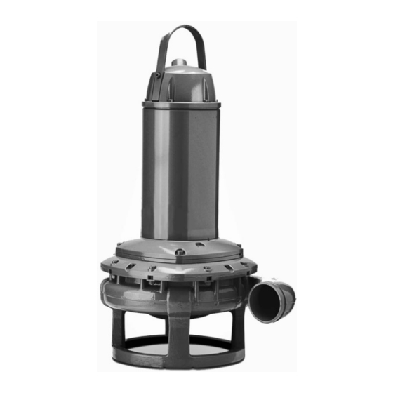
3 Product Description 3.3 Parts Figure 1: Without cooling jacket Figure 2: With cooling jacket Position Part Description Motor For information about the motor, see Technical Reference (page 51). Monitoring For more information about the monitoring equipment equipment, see Monitoring equipment (page 13). -
Page 15: Monitoring Equipment
• Cooling jacket • Inlet/outlet pipes with M16 threads (replacing the coolant plugs) • External cooling system (hose, water source, etc.) Contact your local Grindex representative for more information. 3.4 Monitoring equipment The following applies to the monitoring equipment of the pump: •... -
Page 16: The Data Plate
3 Product Description NOTICE: Thermistors must never be exposed to voltages higher than 2.5 V. If the voltage exceeds this value, for example when the control circuit is tested, then the thermistors will be destroyed. 3.5 The data plate Introduction The data plate is a metal label located on the main body of the pump. -
Page 17: Approvals
3 Product Description These are the data plates for explosion-proof version .190: 3.6 Approvals Product approvals for hazardous locations Pump Approval 8153.190 European Norm (EN) • ATEX Directive • EN 60079-0:2012/A11:2013, EN 60079-1:2007, EN 13463-1:2009, EN 13463-5:2011 • I M2 c Ex d I Mb •... - Page 18 3 Product Description 1. Approval 2. Approval authority and Approval number 3. Approval for Class I 4. Approved for drive unit 5. Stall time 6. Starting current or Rated current 7. Duty class 8. Duty factor 9. Input power 10.Rated speed 11.Controller 12.Additional information 13.Maximum ambient...
-
Page 19: Installation
4 Installation 4 Installation 4.1 Install the pump Before starting work, make sure that the safety instructions in the chapter Introduction and Safety (page 3) have been read and understood. DANGER: Electrical Hazard Before starting work on the unit, make sure that the unit and the control panel are isolated from the power supply and cannot be energized. -
Page 20: Make The Electrical Connections
4 Installation Authority regulation Vent the tank of a sewage station in accordance with local plumbing codes. Fasteners • Only use fasteners of the correct size and material. • Replace all corroded or damaged fasteners. • Make sure that all the fasteners are correctly tightened and that there are no missing fasteners. - Page 21 If the outer sheath of the cable is damaged, then replace the cable. Contact a Grindex service shop. • The voltage drop in long cables must be taken into account. The drive unit’s rated voltage is the voltage measured at the cable connection point in the pump.
-
Page 22: Prepare The Subcab Cables
4 Installation ® 4.2.1 Prepare the SUBCAB cables This section applies to SUBCAB cables with twisted-pair control cores. ® The prepared SUBCAB cable The prepared screened SUBCAB cable ® ® 1. T1+T2 twisted pairs in control element 1. T1+T2 and T3+T4 twisted pairs in control element 2. -
Page 23: Connect The Motor Cable To The Pump
4 Installation Leave a short piece uncovered. c) If applicable, put a cable lug on the screened ground core. d) Twist all power core screens together to create a ground (earth) core and fit a cable terminal to the end. e) Check that the ground (earth) core is at least 10% longer than the phase cores in the cabinet. -
Page 24: Connect The Motor Cable To The Starter And Monitoring Equipment
4 Installation 7. Make sure that any thermal contacts incorporated in the pump are properly connected to the terminal board. 8. Install the entrance cover and the O-ring on the stator housing. 9. Fasten the screws on the entrance flange so that the cable insertion assembly bottoms out. - Page 25 4 Installation T1 T2 Figure 4: Phase sequence Connection locations The figures in this section illustrate how to interpret the connection strip symbols. 1. Stator leads 2. Terminal board 3. Power cable leads L1 L2 L3 T1 T2 T3 T4 4.
- Page 26 4 Installation 1. Starter equipment and mains leads (L1, L2, L3) 2. ground (earth) 3. Functional ground 4. Control leads (T1, T2, T3, T4) L1 L2 L3 T1 T2 T3 T4 5. Thermal contact 6. FLS 7. FLS 10 8. CLS 9.
- Page 27 4 Installation Colors and markings of leads Motor Connection Colors and marking of the main leads Mains SUBCAB SUBCAB 7GX SUBCAB 4GX COLOR STANDARD STATOR LEADS SUBCAB AWG Screened Screenflex 7GX Screenflex 4GX BN = Brown U1,U5 = RD BK 1 BK = Black = GN BK 2...
- Page 28 4 Installation 6-leads connection U2 V2 W1V2 Only applicable to 70mm2 terminal clamp One cable Two cables V1 U2 U1 W2 W1 V2 One cable Two cables U1W2 V1 U2 W1V2 Two cables One cable L2:1 L3:1 L1:1 L2:2 L3:2 L1:2 Figure 5: One cable (left) and two cables (right) 8153.020/.190 Bravo 900 Installation, Operation, and Maintenance Manual...
- Page 29 4 Installation 9-leads connection One cable Two cables U1U5 W1W5 U2V2 W2 U2 V2 W2 V1 V5 One cable Two cables Y-SER V5 V2 W1 W5 W2 U1 U5 U2U5V2V5W2W5 U2 V1 Figure 6: One cable (left) and two cables (right) 4.2.4.1 Screened cable connection Cable without separate ground conductor.
-
Page 30: Sensor Connection
4 Installation Screenflex and SUBCAB with functional ground T1 and T2 White insulation hose T1 and T2 White insulation hose twisted* twisted* Screen Screen T1 T2 * For screened SUBCAB T3 & T4 shall also be twisted separately Figure 8: Screenflex and SUBCAB with functional ground *For screened SUBCAB T3 and T4 shall also be twisted separately. -
Page 31: Check The Impeller Rotation
4 Installation 4.2.5.2 Connection to the monitoring equipment MiniCAS II Pump contactor 24 V AC/DC CC Control circuit L1 Caution light (leakage) L2 Caution light (stator over- temperature) 12 VDC Pump main supply FLS10 Reset switch WS002623B 4.3 Check the impeller rotation CAUTION: Crush Hazard The starting jerk can be powerful. - Page 32 4 Installation The correct direction of impeller rotation is clockwise when you look at the pump from above. 4. If the impeller rotates in the wrong direction, then transpose two phase leads (3-phase) and do this procedure again. 8153.020/.190 Bravo 900 Installation, Operation, and Maintenance Manual...
-
Page 33: Operation
5 Operation 5 Operation 5.1 Precautions Before taking the unit into operation, check the following: • All recommended safety devices are installed. • The cable and cable entry have not been damaged. • All debris and waste material has been removed. NOTICE: Never operate the pump with the discharge line blocked, or the discharge valve closed. - Page 34 5 Operation 1. Check the coolant level in the seal housing. 2. Remove the fuses or open the circuit breaker, and check that the impeller can rotate freely. WARNING: Crush Hazard Never put your hand into the pump housing. 3. Conduct insulation test phase to ground. To pass, the value must exceed 5 megaohms.
-
Page 35: Maintenance
6 Maintenance 6 Maintenance Precautions Before starting work, make sure that the safety instructions in the chapter Introduction and Safety (page 3) have been read and understood. DANGER: Crush Hazard Moving parts can entangle or crush. Always disconnect and lock out power before servicing to prevent unexpected startup. -
Page 36: Torque Values
6 Maintenance 6.1 Torque values All screws and nuts must be lubricated to achieve correct tightening torque. Screws that are screwed into stainless steel must have the threads coated with suitable lubricants to prevent seizing. If there is a question regarding the tightening torques, please contact the local sales and service representative. -
Page 37: Empty The Coolant
6 Maintenance 1. Inspection plug 2. Coolant plugs 6.2.1 Empty the coolant CAUTION: Compressed Gas Hazard Air inside the chamber may cause parts or liquid to be propelled with force. Be careful when opening. Hold a rag over the plug to prevent liquid from spraying out. - Page 38 6 Maintenance 3. If it is necessary to separate the drive unit from the hydraulic unit, then do the following: a) Carefully open the coolant plugs to relieve any built-up pressure inside the cooling jacket. CAUTION: Compressed Gas Hazard Air inside the chamber may cause parts or liquid to be propelled with force.
-
Page 39: Fill With Coolant
If DOWCAL 200 ™ from Dow Chemical Company is not available, then contact your local Grindex representative. The monopropylene glycol must fulfill the Grindex material standard M0800.82.0002. NOTICE: Deionized or distilled water must be used in the water-glycol mixture. -
Page 40: Replace The Impeller
Required tools: • 17 mm hexagon bit adapter with an extension of at least 125 mm (4.92 in.) • Impeller puller If applicable, contact your local Grindex representative for correct type and size. • Chain • Rod (wooden or copper) for locking the impeller in place, if applicable. -
Page 41: Remove The Impeller
6 Maintenance WARNING: • If you fail with the impeller installation, you must redo the installation procedure from the beginning. • When laying the pump on its side, do not allow the weight of the pump to rest on any portion of the impeller. The impeller must not be allowed to make contact with the concrete floor or other hard and rough surfaces. - Page 42 6 Maintenance WS002416A 4. Secure the wearing cover: a) Place the drive unit horizontally. WARNING: When laying the pump on its side, do not allow the weight of the pump to rest on any portion of the impeller. The impeller must not be allowed to make contact with the concrete floor or other hard and rough surfaces.
-
Page 43: Install The Impeller
6 Maintenance 6.3.2 Install the impeller NOTICE: If you fail with the impeller installation, you must redo the installation procedure from the beginning. 1. Prepare the shaft: a) Polish off any flaws with a fine emery cloth. The end of the shaft must be clean and free from burrs. b) Coat the inner conic, the outer cylindrical surfaces, and the thread of the conical sleeve with a thin layer of grease. - Page 44 6 Maintenance 3. Mount the pump housing: a) Lubricate the pump housing screws. b) Place the drive unit in the pump housing. c) Tighten the screws in a diagonal sequence. For tightening torque, see Torque values (page 34). WS002416A 4. Lock the impeller: a) Place the pump in a horizontal position.
-
Page 45: Replace The Agitator
6 Maintenance a) Fit the lubricated washer and impeller screw. b) Tighten the impeller screw. For tightening torque, see Torque values (page 34). c) Tighten it a further 1/8 turn (45°). d) Fit the wear protection/plug. e) Remove the chain from the impeller and pump housing. 7. -
Page 46: Install The Agitator Unit
Initial To make a check up of the pump Within the first year of inspection condition by an authorized Grindex operation. service representative and, based on the result and findings from these measures, to determine the intervals for periodical inspection and major overhaul for the specific installation. -
Page 47: Inspection
6 Maintenance Type of Purpose Inspection interval service Major To secure a long operating lifetime for Up to 8,000 hours or 3 overhaul the product. It includes replacement of years, whichever comes key components and the measures first. taken during an inspection. These intervals apply to normal applications and operating conditions at... -
Page 48: Major Overhaul
6 Maintenance Service item Action Rotation direction Check the impeller rotation. Seal housing 1. Fill with new coolant, if necessary. 2. Check that the freezing point is lower than -13°C (9°F). Terminal board Check that the connections are properly secured. Thermal contacts Normally closed circuit;... -
Page 49: Troubleshooting
• The sensor indicators do not indicate an alarm. • The overload protection is not tripped. If the problem still persists: Contact the local Grindex service shop. The pump does not start Check that: automatically, but can be • The start level regulator is functioning. Clean or started manually. -
Page 50: The Pump Does Not Stop When A Level Sensor Is Used
• The sump in order to prevent the impeller from clogging again. If the problem persists, contact the local Grindex service shop. Always state the product number and the serial number of your pump when you contact Grindex, Product Description (page 11). -
Page 51: The Pump Starts-Stops-Starts In Rapid Sequence
• Whether the voltage drop in the line at the starting surge causes the contactor's self-holding malfunction. If the problem persists, contact the local Grindex service shop. Always state the product number and the serial number of your pump when you contact Grindex, Product Description (page 11). -
Page 52: The Pump Delivers Too Little Or No Water
There is a malfunction in Replace the overload protection. the overload protection. If the problem persists, contact the local Grindex service shop. Always state the product number and the serial number of your pump when you contact Grindex, Product Description (page 11). -
Page 53: Technical Reference
Description Liquid temperature 40°C (104°F) maximum pH of the pumped media (liquid) 5.5–14 Liquid density Contact the nearest Grindex representative Depth of immersion Maximum 20 m (65 ft) Other For the specific weight, current, voltage, power ratings, and speed of the pump, see the data plate of the pump. - Page 56 Visit our Web site for the latest version of this document and more information Gesällvägen 33 174 07 Sundbyberg The original instruction is in English. All non-English www.grindex.com instructions are translations of the original instruction. Sweden Tel: +46-8-606 66 00 © 2011 Grindex Fax: +46-8-745 53 28 www.grindex.com 899402_8.0_en-US_2016-09_IOM.8153...
Need help?
Do you have a question about the Bravo 900 8153.190 and is the answer not in the manual?
Questions and answers