
Related Manuals for Grindex Master 8105.082


Summary of Contents for Grindex Master 8105.082
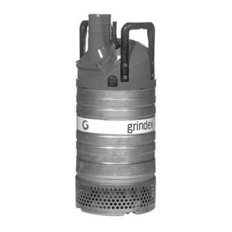
- Page 1 Revision 2.0 Installation, Operation, and Maintenance Manual 8105.082/182 Master...
-
Page 3: Table Of Contents
Table of Contents Table of Contents Introduction and Safety......................3 Introduction................... 3 Safety terminology and symbols............... 3 Product warranty..................4 Safety....................5 User safety.................... 5 Environmental safety................7 Transportation and Storage....................8 Inspect the delivery................8 Inspect the package................8 Inspect the unit................... 8 Transportation guidelines................. - Page 4 Table of Contents The pump does not start................ 47 The pump does not stop when a level sensor is used......... 48 The pump starts-stops-starts in rapid sequence........49 The pump runs but the motor protection trips........... 49 The pump delivers too little or no water........... 50 The pump does not start when a softstarter is used........
-
Page 5: Introduction And Safety
Introduction and Safety Introduction and Safety Introduction Purpose of this manual The purpose of this manual is to provide necessary information for: • Installation • Operation • Maintenance CAUTION: Read this manual carefully before installing and using the product. Improper use of the product can cause personal injury and damage to property, and may void the warranty. -
Page 6: Product Warranty
• The product is used only under the conditions described in this manual. • The monitoring equipment incorporated in the product is correctly connected and in use. • All service and repair work is done by personnel authorized by Grindex. • Genuine Grindex parts are used. Limitations The warranty does not cover faults caused by the following: •... -
Page 7: Safety
This includes any modification to the equipment or use of parts not provided by Grindex. If there is a question regarding the intended use of the equipment, please contact an Grindex representative before proceeding. - Page 8 Introduction and Safety Electrical connections Electrical connections must be made by certified electricians in compliance with all international, national, state, and local regulations. For more information about requirements, see sections dealing specifically with electrical connections. Hazardous liquids The product is designed for use in liquids that can be hazardous to your health. Observe these rules when you work with the product: •...
-
Page 9: Environmental Safety
1. Follow local laws and regulations regarding recycling if the unit or parts are accepted by an authorized recycling company. 2. If the first guideline is not applicable, then return the unit or parts to the nearest Grindex representative. 8105.082/182 Master Installation, Operation, and Maintenance Manual... -
Page 10: Transportation And Storage
Transportation and Storage Transportation and Storage Inspect the delivery Inspect the package 1. Inspect the package for damaged or missing items upon delivery. 2. Note any damaged or missing items on the receipt and freight bill. 3. File a claim with the shipping company if anything is out of order. If the product has been picked up at a distributor, make a claim directly to the distributor. -
Page 11: Temperature Ranges For Transportation, Handling And Storage
Transportation and Storage Temperature ranges for transportation, handling and storage Handling at freezing temperature At temperatures below freezing, the product and all installation equipment, including the lifting gear, must be handled with extreme care. Make sure that the product is warmed up to a temperature above the freezing point before starting up. -
Page 12: Product Description
Always follow the limits given in Application limits (page 54). If there is a question regarding the intended use of the equipment, please contact a Grindex representative before proceeding. WARNING: In explosive or flammable environments, only use Ex- or MSHA-approved products. -
Page 13: The Data Plate
Product Description The data plate Introduction The data plate is a metal label located on the main body of the pump. The data plate lists key product specifications. The data plate Pump type number Frequency Phases, type of current Rated shaft power Thermal class Locked rotor code-letter Country of origin... - Page 14 Product Description The MSHA approval plate 8105.082/182 Master Installation, Operation, and Maintenance Manual...
-
Page 15: Installation
Installation Installation Install the pump DANGER: Disconnect and lock out electrical power before installing or servicing the unit. WARNING: • Do not install the starter equipment in an explosive zone unless it is explosion-proof rated. • Do not install CSA-approved products in locations that are classified as hazardous in the national electric code, ANSI/NFPA 70-2005. -
Page 16: Install
Installation Figure 1: Settling pump-sump Discharge line requirements The discharge line can be run vertically or horizontally, but must be without sharp bends. Proper horizontal and vertical installation Improper installation with a sharp bend Fasteners WARNING: • Only use fasteners of the proper size and material. •... -
Page 17: Make The Electrical Connections
Installation Heavier pumps must be lifted and lowered down by crane. Suspend the pump by the lifting handle or the eyebolts with chains or wires. 4. Place the pump on the base and make sure it cannot fall over or sink. The base should consist of a plank, a bed of coarse gravel, or a cut-down and perforated oil drum. - Page 18 If the outer sheath of the cable is damaged, then replace the cable. Contact a Grindex service shop. • The voltage drop in long cables must be taken into account. The drive unit’s rated voltage is the voltage measured at the cable connection point in the pump.
-
Page 19: Connect The Motor Cable To The Pump
Installation Earth (ground) conductor length The earth (ground) conductor must be 200mm (7.9 in) longer than the phase conductors in the junction box of the unit. Connect the motor cable to the pump CAUTION: Leakage into the electrical parts can cause damaged equipment or a blown fuse. Keep the end of the motor cable above the liquid level. - Page 20 Installation Control leads (T1, T2, T3, T4) Softstarter Phase shifter Level regulator Diode Contactor, start relay or thermal relay Motor cable Thermal detector in stator Screen Thermal detector in main bearing Pump Jumper Crimp connection Terminal board, terminal plate Crimp isolation Leakage sensor Motor protector Stator leads (U1, U2, U5, U6, V1,...
- Page 21 Installation Stator leads and thermal contacts connection to the terminal plate Terminal plate 8105.182 51 672 00 STATOR LEADS AND THERMAL CONTACTS STATOR LEADS 9 leads 9 leads 12 leads 12leads 12 leads 3 leads 6 leads 6 leads Terminal Y serial Y // Y //...
- Page 22 Installation Motor cable and starter unit connection to the terminal plate Terminal SYMBOLS AND DENOMINATIONS plate BN=Brown =Terminal plate BK=Black =Screen WH=White =Ground OG=Orange GN=Green =Functional ground 8105.182 GNYE=Green-Yellow =Crimp isolation RD=Red =Crimp connection GY=Grey BU=Blue =Flat pin sleeve YE=Yellow =Inside pump Pump *SUBCAB AWG/CSA...
-
Page 23: Cable Charts, Msha Version
Installation Cable charts, MSHA version Motor 60 Hz, 3-phase, 440-480V Y or 575-600V Y WS004859A Check the impeller rotation: Pumps without built-in motor protection ™ Follow this procedure if your product does not have the rotation control SMART or softstarter. WARNING: The starting jerk can be powerful. -
Page 24: Check The Phase Sequence: Pumps With Built-In Motor Protection
Installation Figure 2: Start reaction 4. If the impeller rotates in the wrong direction, then do the following: • If the motor has a 3-phase connection, then transpose two phase conductors and repeat this procedure from step 1. For 3-phase pumps with external starters or without built-in motor protection, the phases must be shifted on the output terminal of the starter. - Page 25 Installation Figure 3: Start reaction 1. Connect the pump to power as follows: Condition Action The pump has a CEE plug with Connect the plug. internal phase shifter. The pump has a phase shifter with an Turn the knob on the phase shifter in on/off switch.
- Page 26 Installation Condition Action The pump has a CEE plug with 1. Pull out the plug. internal phase shifter. 2. Shift two phases. 3. Wait until the motor has stopped. 4. Connect the plug. The pump has a phase shifter with an 1.
-
Page 27: Operation
Operation Operation Precautions WARNING: • Never operate the pump without safety devices installed. • Never operate the pump with the discharge line blocked, or the discharge valve closed. • Make sure you have a clear path of retreat. • Never work alone. CAUTION: If the pump is equipped with automatic level control and/or internal contactor, there is a risk of sudden restart. -
Page 28: Clean The Pump
Operation WARNING: • Make sure that the unit cannot roll or fall over and injure people or damage property. • In some installations, the pump and the surrounding liquid may be hot. Bear in mind the risk of burn injuries. •... -
Page 29: Maintenance
Maintenance Maintenance Precautions DANGER: Disconnect and lock out electrical power before installing or servicing the unit. WARNING: • Always follow safety guidelines when working on the product. See Introduction and Safety (page 3). • Make sure that the unit cannot roll or fall over and injure people or damage property. -
Page 30: Torque Values
Maintenance Figure 4: Example of O-ring adjacent surfaces During the reassembly, always make sure that existing index markings are in line. The reassembled drive unit must always be insulation-tested and the reassembled pump must always be test-run before normal operation. Torque values All screws and nuts must be lubricated to achieve correct tightening torque. -
Page 31: Service
Maintenance Propert y class 12.9 17 (13) 40 (30) 79 (58) 136 1120 2210 (3.6) (7.2) (100) (245) (480) (825.1) (1630) Hexagon screws with countersunk heads For hexagon socket head screws with countersunk head, maximum torque for all property classes must be 80% of the values for property class 8.8 above. Service Regular inspection and service of the pump ensures more reliable operation. - Page 32 Maintenance Service item Action Check the oil: 1. Take an oil sample. 2. If the oil contains particles, then replace the mechanical seal. Contact an authorized service shop. Make sure that the volume is filled to the correct level. See Fill with oil (page 32).
-
Page 33: Major Overhaul
Maintenance Major overhaul For a major overhaul, take this action in addition to the tasks listed under Inspection. Service item Action Support and main Replace the bearings with new bearings. bearing Mechanical seal Replace with new seal units. Change the oil A paraffin oil with viscosity close to ISO VG32 is recommended. -
Page 34: Replace The Impeller
Maintenance Fill with oil 1. Replace the oil screw O-ring. 2. Put one of the oil screws back and tighten it. 3. Turn the pump so that the oil hole faces upwards and fill with new oil. Fill until the oil level reaches the inlet hole. Quantity: 1.45 L (1.53 qt) 4. - Page 35 Maintenance 2. Remove the suction cover. 3. Remove the O-ring. 4. Loosen the impeller: a) Lock the impeller to prevent rotation. Use pliers, a screwdriver, or similar. b) Remove the impeller screw and washer. 5. Remove the impeller: a) Lock the impeller to prevent rotation. Use pliers, a screwdriver, or similar.
-
Page 36: Remove The Impeller Sh
Maintenance c) Pull off the impeller. Remove the impeller SH WARNING: A worn impeller and/or pump housing can have very sharp edges. Wear protective gloves. 1. Remove the strainer. 2. Remove the suction cover. 3. Remove the O-ring. 4. Loosen the impeller: a) Lock the impeller to prevent rotation. - Page 37 Maintenance 5. Remove the impeller: a) Lock the impeller to prevent rotation. Use pliers, a screwdriver, or similar. b) Turn the adjustment screw counterclockwise until the impeller breaks free from the shaft. Use a 10 mm hexagon bit adapter (Allen socket) with a 100 mm (4 in.) extension.
-
Page 38: Install The Impeller N, H
Maintenance 7. Remove the inner diffuser. 8. Remove the upper diffuser. 9. Remove the impeller: a) Lock the impeller to prevent rotation. Use pliers, a screwdriver, or similar. b) Turn the adjustment screw counterclockwise until the impeller breaks free from the shaft. Use a 10 mm hexagon bit adapter (Allen socket) with a 100 mm (4 in.) extension. - Page 39 Maintenance 2. Align the edge of the adjustment screw with the edge of the conical sleeve so that they are flush. WS001759A 3. Grease the threads of the impeller screw and the washer. The proper lubrication of the screw and washer is lubricating grease for assembly of bolts etc., for example, Kluber ALTEMP Q NB 50 or equivalent.
- Page 40 Maintenance 7. Mount the suction cover with its O-ring and tighten. Tightening torque: 44 Nm (32.5 ft-lbs) 8. Turn the adjustment screw clockwise until the impeller makes contact with the suction cover.Tighten a further 1/8 turn, 45°. This will ensure the correct clearance between the impeller and the suction cover in the next step.
-
Page 41: Install The Impeller Sh
Maintenance The screw will be loaded to its yield point and the load capacity of the joint will be higher. e) Check that the impeller can rotate easily. 10. Mount the strainer and the nuts. Tightening torque: 44 Nm (32.5 ft-lbs) Install the impeller SH 1. - Page 42 Maintenance The proper lubrication is grease for bearings, for example Exxon Mobil Unirex N3, Mobil Mobilith SHC 220 or equivalent. NOTICE: Surplus grease can cause the impeller to become loose. Remove surplus grease from conical and/or cylindrical surfaces of shafts and/or sleeves. 2.
- Page 43 Maintenance 7. Mount the suction cover with its O-ring and tighten. Tightening torque: 44 Nm (32.5 ft-lbs) 8. Turn the adjustment screw clockwise until the impeller makes contact with the suction cover. This will ensure the correct clearance between the impeller and the suction cover in the next step.
- Page 44 Maintenance 9. Remove the suction cover. 10. Remove the O-ring. 11. Align the edge of the lower adjustment screw with the edge of the lower conical sleeve so that they are flush. WS001759A 12. Assemble the lower conical sleeve and the lower impeller onto the shaft end of the upper impeller.
- Page 45 Maintenance 13. Mount the suction cover with its O-ring and tighten. Tightening torque: 44 Nm (32.5 ft-lbs) 14. Turn the lower adjustment screw clockwise until the lower impeller makes contact with the suction cover. Tighten a further 1/6 turn, 60°. This will ensure the correct clearance between the lower impeller and the suction cover in the next step.
- Page 46 Maintenance 15. Fasten the impeller: a) Place the washer on the impeller screw. b) Lock the impeller to prevent rotation. Use pliers, a screwdriver, or similar. c) Tighten the impeller screw. Tightening torque: 44 Nm (32.5 ft-lbs) d) Tighten a further 1/8 turn, 45°. The screw will be loaded to its yield point and the load capacity of the joint will be higher.
- Page 47 Maintenance 8105.082/182 Master Installation, Operation, and Maintenance Manual...
-
Page 48: Troubleshooting
Troubleshooting Troubleshooting Introduction DANGER: Personal injury hazard. Troubleshooting a live control panel exposes personnel to hazardous voltages. Electrical troubleshooting must be done by a qualified electrician. Failure to follow these instructions will result in serious personal injury, death, and/or property damage. Follow these guidelines when troubleshooting the pump: •... -
Page 49: The Pump Does Not Start, For Pumps With Smart Or Softstarter
• If no glove or phase shifter is used, then shift two phase conductors in the cabinet. If the problem persists, contact the local Grindex service shop. Always state the product number and the serial number of your pump when you contact Grindex, Product Description (page 10). -
Page 50: The Pump Does Not Stop When A Level Sensor Is Used
• The sump in order to prevent the impeller from clogging again. If the problem persists, contact the local Grindex service shop. Always state the product number and the serial number of your pump when you contact Grindex, Product Description (page 10). -
Page 51: The Pump Starts-Stops-Starts In Rapid Sequence
The stop level is set too Raise the stop level. low. If the problem persists, contact the local Grindex service shop. Always state the product number and the serial number of your pump when you contact Grindex, Product Description (page 10). -
Page 52: The Pump Delivers Too Little Or No Water
The pump will restart automatically after a corrected phase fault or power cut. If the problem persists, contact the local Grindex service shop. Always state the product number and the serial number of your pump when you contact Grindex, Product Description (page 10). -
Page 53: The Pump Does Not Start When A Softstarter Is Used
• Depending on the installation type, add a means for priming the pump, such as a foot valve. If the problem persists, contact the local Grindex service shop. Always state the product number and the serial number of your pump when you contact Grindex, Product Description (page 10). - Page 54 Troubleshooting Potentiometer Function More powerful Smoother start start Ramp up time Lower than default Higher than default [Ramp U] Ramp down time [Ramp D] Initial torque Higher than default Lower than default [Torque] Status Alarm signal Power supply on Green, continuous Ramping Yellow, intermittent Bypass relay ON...
- Page 55 LED F is ON. Transpose two phase leads for L1, L2, L3 outside the pump. If the problem persists, contact the local Grindex service shop. Always state the product number and the serial number of your pump when you contact Grindex, Product Description (page 10).
-
Page 56: Technical Reference
For specific weight, current, voltage, power rating, and speed of the pump, see the data plate on the pump. For starting current, see Motor data (page 54). For other applications, contact the nearest Grindex representative for information. Motor data Feature Description... -
Page 57: Specific Motor Data, Standard Version
Technical Reference Specific motor data, standard version 3-phase, 50 Hz Motor type: • 2,855 rpm • Rated output 10 kW (13.4 hp) • Maximum power consumption 11.7 kW (15.7 hp) Voltage, V Rated Current, A Starting current, Power factor, cos φ... -
Page 58: Specific Motor Data, Msha Version
Technical Reference Voltage , V Rated Starting Power factor, Current, A current, A cos φ 400 D 400 Y parallel 440 D 0.89 440 D serial 0.92 440 Y serial 0.92 460 D 0.84 460 D serial 0.91 460 Y serial 0.91 480 D 0.79... - Page 59 Technical Reference Standard version ISO-G 6A ISO-G 6A NPT 6-8 NPT 6-8 150 House size 150 House size *Victaulic 6" *Victaulic 6" Tandem connection ISO-G 6A NPT 6-8 150 Hose size *Victaulic 6" Weight (kg) *Designed for "Victaulic Coupling, Total Weight (kg) according to ANSI/AWWA C606-97 Total...
- Page 60 Technical Reference ISO-G 4A ISO-G 4A NPT 4-8 NPT 4-8 100 House size 100 House size *Victaulic 4" *Victaulic 4" Tandem connection ISO-G 4A NPT 4-8 100 Hose size *Victaulic 4" Weight (kg) *Designed for "Victaulic Coupling, Weight (kg) Total according to ANSI/AWWA C606-97 Total SCREEN OPENING...
- Page 61 Technical Reference ISO-G 3A ISO-G 3A NPT 3-8 NPT 3-8 75 House size 75 House size *Victaulic 3" *Victaulic 3" Tandem connection ISO-G 3A NPT 3-8 75 Hose size *Victaulic 3" *Designed for "Victaulic Coupling, Weight (kg) Weight (kg) according to ANSI/AWWA C606-97 Total Total *Designed for "Victaulic Coupling,...
- Page 62 Technical Reference ISO-G 3A ISO-G 3A NPT 3-8 NPT 3-8 75 House size 75 House size *Victaulic 3" *Victaulic 3" Tandem connection ISO-G 3A NPT 3-8 75 Hose size *Victaulic 3" Weight (kg) *Designed for "Victaulic Coupling, Total Weight (kg) according to ANSI/AWWA C606-97 Total SCREEN OPENING...
- Page 63 Technical Reference ISO-G 4A ISO-G 4A NPT 4-8 NPT 4-8 100 House size 100 House size *Victaulic 4" *Victaulic 4" Tandem connection ISO-G 4A NPT 4-8 100 Hose size *Victaulic 4" Weight (kg) *Designed for "Victaulic Coupling, Total according to ANSI/AWWA C606-97 Weight (kg) SCREEN OPENING Total...
- Page 64 Technical Reference MSHA version Figure 19: MSHA version, N 8105.082/182 Master Installation, Operation, and Maintenance Manual...
- Page 65 Technical Reference Figure 20: MSHA version, H 8105.082/182 Master Installation, Operation, and Maintenance Manual...
-
Page 66: Performance Curves
Technical Reference Figure 21: MSHA version, SH Performance curves Test standard Pumps are tested in accordance with ISO 9906:2012, HI 11.6:2012. 8105.082/182 Master Installation, Operation, and Maintenance Manual... - Page 67 Technical Reference Standard pump version, 50 Hz P [kW] H [m] Q [l/s] WS006722A Figure 22: N, H P [kW] H [m] Q [l/s] WS006723A Figure 23: SH 8105.082/182 Master Installation, Operation, and Maintenance Manual...
- Page 68 Technical Reference Standard pump version, 60 Hz P [hp] / [kW] H [ft] / [m] 0 100 200 300 400 500 600 700 800 900 Q [l/s] / [usgpm] WS006724A Figure 24: N, H P [hp] / [kW] H [ft] / [m] Q [l/s] / [usgpm] WS006725A Figure 25: SH...
- Page 69 Technical Reference MSHA pump version, 60 Hz [hp] / [kW] H [ft] / [m] Q [l/s] / [usgpm] Figure 26: N, H (HP) (kW) 20 Q (l/s) (gpm) H (ft) Q (l/s) (gpm) Figure 27: SH 8105.082/182 Master Installation, Operation, and Maintenance Manual...
- Page 72 Visit our Web site for the latest version of this document and more information Gesällvägen 33 174 87 Sundbyberg The original instruction is in English. All non-English www.grindex.com instructions are translations of the original instruction. Sweden Tel: +46-8-606 66 00 © 2012 Grindex Fax: +46-8-745 53 28 www.grindex.com 883981_2.0_en-US_2013-04_IOM_8105.082/182...
Need help?
Do you have a question about the Master 8105.082 and is the answer not in the manual?
Questions and answers