Table of Contents
Advertisement
Quick Links
Advertisement
Table of Contents

Related Manuals for Schletter FIX Z PRO


Summary of Contents for Schletter FIX Z PRO
- Page 1 FIX Z PRO INSTALLATION MANUAL V1.0 LAST REVISED ON 02.02.2024...
-
Page 2: Table Of Contents
TABLE OF CONTENTS 1.0 Introduction ..........................2 1.1 Short Description of the system ..................2 1.2 Scope of the Installation Manual ..................2 1.3 Appropriate Use/Warnings ....................2 1.4 Safety Instructions ......................3 2.0 System Overview ........................4 2.1 System Setup ........................4 2.2 Components Details ...................... -
Page 3: Introduction
This applies if the system is used under other load, climatic and/or corrosion conditions than originally assumed. Schletter Australia is in no case responsible for damages to the product itself or consequential damages caused by the product which are the result of an inappropriate handling of the product. -
Page 4: Safety Instructions
1.4 Safety Instructions Read and understand these safety instructions carefully before starting the assembly and keep them safely at hand. Comply with all regional and national valid standards, building regulations and accident prevention regulations. Break hazard! PV modules may be damaged if stepped on. Planning, installation and commissioning of the solar power system must only be performed by qualified technical personnel. -
Page 5: System Overview
2.0 System Overview 2.1 System Setup – FixZ Pro Key Components FixZ Pro Rail Fastener Elevation Element Module Support Pro Rail Joiner Proline Accessories ➢ Module Cable Clips ➢ Optimiser Kit ➢ Earthing Lugs ➢ Earthing Shims WE SUPPORT SOLAR P a g e 4 | 18... -
Page 6: Components Details
2.2 Components Details WE SUPPORT SOLAR P a g e 5 | 18... - Page 7 WE SUPPORT SOLAR P a g e 6 | 18...
- Page 8 WE SUPPORT SOLAR P a g e 7 | 18...
- Page 9 WE SUPPORT SOLAR P a g e 8 | 18...
-
Page 10: Installation Tools
Installation Tools Tape Measure Chalk Line Marker Pliers Angle Grinder Carpenter’s Square Rubber Mallet Torque Wrench Wrench Rechargeable Power Drill Torx® bit (TX 40) WE SUPPORT SOLAR P a g e 9 | 18... -
Page 11: Mounting Instructions
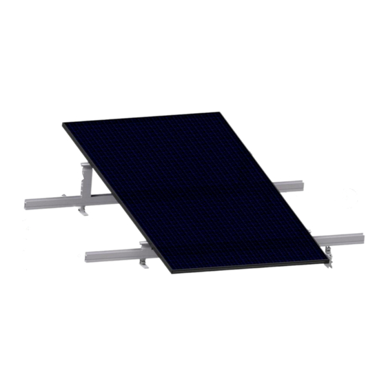
Mounting Instructions 4.1 Tilt Frames 4.1.1 FixZ Pro Configurations The FixZ Pro system can be oriented at 5 , 10 and 15 for panels as shown in [Fig 4.1.1]. This is achieved by the use of elevation elements: • Tilt – 1 Elevation Element •... -
Page 12: Fixz Pro Setup
4.1.2 FixZ Pro Setup I. The fasteners (Rapid Pro SMLs or Seam Clamps), based on the roofing sheet application, are positioned as per the installation plan. The variables A, B and C as per [Fig 4.1.2] need to be determined at the site before securing the FixZ Pro frames to the roof purlins. -
Page 13: Rail Installation
4.2 Rail Installation 4.2.1 Choice of rail The FixZ Pro rails come in standard sizes of 4400mm. 4.2.2 Add Rail Splice I. To increase the array length, rails can be spliced together using rail joiners [Fig 4.2.2A]. II. Insert half of internal splice into first rail, push until it reaches midpoint where the stop tab is located under the splice [Fig 4.2.2B]. -
Page 14: Fixz Pro Rail + Elevation Element + Module Support Pro
4.2.3 FixZ Pro Rail + Elevation Element + Module Support Pro The FixZ rails are positioned by placing the square channel at the bottom of the rail on top of the multi-adapter. The higher side of the rail, A, should be facing down the slope of the roof for both the top and bottom rails. -
Page 15: Module Mounting
4.3 Module Mounting 4.3.1 Position Modules I. Position end clamps on rail approximately 20mm from end of rail, do not tighten [Fig 4.3.1]. II. Position first module and secure using pre- positioned end clamps, do not tighten. III. Attach middle clamps to rail on the exposed side Fig 4.3.1: Positioning end clamp of the first module. -
Page 16: Accessories
4.4.1 Micro-Inverter/Optimiser Kit Proline The optimiser kits enable the mounting of optimisers and micro- inverters on top of Fix Z Pro rails: Add an additional Module Support Pro to either the top or bottom row of the PV array, as shown in [Fig 4.4.1]. -
Page 17: Rail Cable Clip
For project specific system design, please refer to project specific drawings for recommended torque for each size of bolt used in the system and allowable tolerances. In the event of deviation from approved drawings, contact Schletter Australia immediately. WE SUPPORT... -
Page 18: Maintenance
Tighten all non-conforming bolts to specified torques as per section 6.5. Check for loose wiring. The maintenance guidelines above apply only to the components of the mounting structure that are manufactured from Schletter. For external components, maintenance should be carried out respective to relevant manufacturer’s guidelines. WE SUPPORT... - Page 19 SCHLETTER SOLAR GMBH UNIT 4, 27 WILLIAMSON ROAD 2565 INGLEBURN AUSTRALIA P: (02) 9426 7800 WWW.SCHLETTER-GROUP.COM WE SUPPORT We reserve the right to changes, including technical modification. SOLAR P a g e 18 | 18...
Need help?
Do you have a question about the FIX Z PRO and is the answer not in the manual?
Questions and answers